309 | P a g e
WIRE STEERING
Kishor Raghunath Koar
1_Mahesh Jalindhar Kadlag
2_
Pratik Rajendra Khairnar
3 123T.E. Scholar, BVCOE&RI, Nashik, Maharashtra, (India)
ABSTRACT
The automotive industry has already implemented many advanced computer systems in an attempt to increase
safety and comfort of drivers. In parallel with these advancementswe see a big shift from mechanical systems to
electrical systems and steer-by-wire is anotherimplementation that is very promising in terms of safety and
functionality. Already, there are some commercial prototypes of such ‘by-wire’ systems [1] and there is a lot of
research, both academic [2] and commercial [3], in the field. For my Engineering Senior Design Project at
Swarth more College, I chose to work on a steer-by-wire system to gain more insight into controltheory and I
thought the double-control system that provided the crucial feedback to the driverwas an interesting
engineering problem.
I. INTRODUCTION
Unlike the conventional steering system where a hand-operated steering wheel is used to turn the front wheels
through the steering column, steer-by-wire technology removes the mechanical and physical links between the
driver (steering wheel) and the front wheels, and replace them with electronic actuators and other components
.
A steer-by-wire system aims to eliminate the physical connection between the steering wheel and the wheels of
a car by using electrically controlled motors to change the direction of the wheels and to provide feedback to the
driver. Today’s automobiles benefit more and more from the many uses of electronic systems. The integration
of a steer-by-wire system can enhance these systems in many ways. In particular, the handling and the safety of
the cars can be improved significantly. Since a steer-by-wire system is easily modifiable, different drivers will
be able to adjust the system to accommodate their styles and this will enhance handling. I addition, disabled
people and the elderly will benefit immensely from steer-by-wire because they will be able to situate the
steering wheel to meet special needs. Traction control systems are very closely tied with driving safety and they
can be enhanced with steer-by-wire vastly. For instance, in a situation where the car starts over steering (when
the rear of the vehicle heads towards the outside of the corner), the natural instinct of many inexperienced
drivers is to turn the steering wheel towards the inside, which in turn causes more over steer. A steer-by-wire
system could be modified to take control in a situation like this to steer to the outside. Since there are virtually
no physical connections between the steering wheel and the wheels, a steer-by-wire system can be implemented
on different cars easily. The steering wheel could replaced on either side of a car (or anywhere else). Both of
these improvements would reduce costs of production and allow a wider range of designs. The downsides of a
steer-by-wire system are maintenance and power cost. Concievably steer by-wire will use more power than the
currently used system, however considering the power consumption of power steering the power cost will be
310 | P a g e
because they have fewer mechanical parts and will improve safety and therefore help the overall maintenance
costs.
II.DESIGN
Conventional Steering System
Steer-by-Wire System
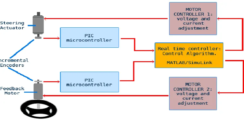
2.1. System Overview
The steer-by-wire system consists of two main parts. The steering section consists of the steering wheel, the
feedback actuator and the feedback actuator angle sensor. The wheel section contains the wheels, the rack and
pinion, a steering actuator and the pinion angle sensor. Figure 2 shows the system components. In my system I
only demonstrated the double control mechanism and did not implement it in a rack and pinion configuration.
The feedback angle sensor provides the steering actuator with its primary input signal and the pinion angle
sensor provides the feedback motor primary signal. The small size of the feedback motor lets the driver rotate
the steering wheel with little difficulty. As soon as the driver starts steering, the control mechanism tries to push
the steering wheel back into place (and the wheels into the position dictated by the current position of the
steering wheel) and this mimics the resistive force of a real steering wheel. However, changing the proportional
311 | P a g e
(with some drawbacks such as more vibration).
Figure 1: Overview of system
3.1.1 Physical Components
3.1.1.1 Steering Actuator
The steering actuator needs to be very powerful in order to turn the wheels of a car when the caries loaded.
Minimizing the effects of unwanted disturbances also requires a powerful motor. In the design, I wanted to use a
small wagon as a model and measurements showed that a motor with a torque of about 80lb-in was necessary.
Ideally this motor would be a brushless DC motor in order to reduce noise and maximize motor life. However,
the high cost and low availability of brushless motors led me to acquire the DC motor shown in Figure 3. This is
a Groschopp 50757, a 88.9 lb-in
312 | P a g e
motor that uses a 12V source and draws approximately 3.4 amps.Initially, I wanted to use a small wagon to
implement my project and show that I could steer the wagon with a person seated on it. In order to find the right
size motor, I put a 200lb weight located in the center of the wagon body and used a 39.5 inch crank to turn the
rack of the wagon. With the wheels on a painted floor the force required was about 1.9lbs (and it never exceeded
2lbs).Thus the total torque was measured to be 39.5 · 2 _ 80lbs.Although this motor has sufficient torque, the
maximum rotation speed is limited to 13.3 RPM Using only 13.3 RPM, it is impossible to simulate rapid
movements experienced in a car, therefore this motor requires gears to increase rotational speed at the expense
of reducing force.
Figure 3: Steering Actuator
The high current characteristics of this motor make it impossible to control using configuration and require a
special controller. The specification sheet for this motor can be found in the appendix .g an H-bridge
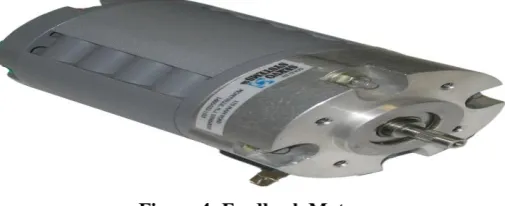
3.1.1.2 Feedback Motor
Figure 4: Feedback Motor
The feedback motor does not have to be as powerful as the steering actuator. In fact, it has to be much less
powerful in order to be turned easily by a driver. I opted to use the motor seen in Figure 4. It was a used motor I
acquired from the department. Initially I tested this motor with full power, and the torque it provided was similar
to the torque felt in a real car and I concluded that this would be a sufficient motor. The power requirements
were also reasonable. It operates at12V and draws less then 1.5A, so the low current requirements allow for an
H-Bridge controller
3.1.1.3Angular Sensors
The angular sensors of the system are very crucial and they need to be very accurate because little erturbations
or errors ultimately make the control of the system much harder for a driver. In a real implementation of a
313 | P a g e
I used two optical digital encoders that were used in a previous project. These are BEI Duncan’s EX-11 and
MX-15 encoders and both of the sensors are seen in Figure 5.
Figure 5: Angular sensors: Incremental encoders
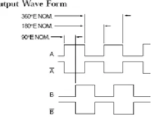
Optical digital encoders’ precision and accuracy make them preferable over potentiometers.They output 1024
pulses per revolution in two channels. The channels have a 90-degree offsetto indicate direction of rotation.
Figure 6 shows the output wave form of the encoders. The specifications of both encoders can be found in the
appendix.
Figure 6: Output wave form of the encoders (taken from the specifications)
3.1.1.4Microcontrollers
The rotary sensors have four possible combinations of outputs and these outputs have to be processed in order to
measure the actual angle of rotation. This is done using the PIC microcontrollers. Once the C code for PICs is
compiled, the ICD interface lets us install the program onto the PIC and the EEPROM technology allows the
program to stay on the PIC even when the power is turned off and on. You can see a picture of the PIC
microcontroller in Figure7, and see the schematics ofthe PIC in Figure 8.I appropriated C code from a project
done by Emery Ku to run the PIC controllers. The code can be found in the appendix. Since the PIC is a digital
device, it only outputs 0 or 5V. In order to get the intermediate values, we have to use the
pulse-width-modulated output of the pics. This is done by coupling the output with a resistor and a capacitor. Depending on
the valuesof the capacitor and resistor, the noise and speed of the output can be varied. I opted for a 12k resistor
and a 33μF capacitor.
3.1.1.5 Electronics
Although most of the control mechanism is done in software, I needed some electronics that provide dsensible
inputs for the controller and regulated the output from the computer to drive the motors. Firstly, since the rotary
encoders did not provide absolute angle information, I used PIC microcontrollers to convert line counts to a
314 | P a g e
could generate voltages from -5 to +5 volts with a resolution of 1.22 mV and the current output is too low to
drive the motors used. Although I never measured the maximum current output, I believe it is in the milliamp
range. At least it is essentially zero compared to 3.4A needed by the steering actuator. Figure 1 shows where the
electronics are located in the system.
Figure7:PICmicrocontroller
Figure 8: PIC microcontroller schematics (courtesy of Erik Cheever).
3.1.1.6 Pulse Width Modulation and the H-Bridge
The feedback motor requires low current and this makes the H-bridge configuration coupled with a pulse width
modulated input signal (seen in Figure 9) a good choice for a controller. The pulse width-modulation uses a
comparator to compare a triangular wave to a user-specified input. The output is a square wave that has a duty
cycle proportional to the specified input. The square waveis very useful because it can be used toswitch
315 | P a g e
Figure 9: Pulse width modulation and the H-Bridge Configuration
The pulse-width modulated signal goes through an inverter (4017) and a buffer 4016) to adjust the voltage to a
range of 0-12V instead of the comparator output range of 0–5V. The outputs ofthe buffer and inverter are
adjusted using a resistor between the outputs and a 12V source. Using the same source for the H-bridge and the
output adjustment is a good idea because that way the gate and drain voltages of the mosfets are adjusted
accordingly. The H-Bridge takes its name from the way it looks (see Figure 9). It consists of pairs of P-channel
and N-channel mosfets. The right side and the left side of the H-bridge get exactly opposite signals and since the
pulse-width-modulated signal runs the gate voltages, we get a very quick switching effect through the motor.
Note that at a given time we only have P1 and N1 (which are on opposite sides) or P2 and N2 in operation. The
current direction keeps changing and the motor stays idle when the duty cycle is 50%. When the duty cycle
increases (or decreases), it allows more current to flow though the motor in one direction than the other and thus
the motor starts rotation. One drawback of the h-bridge is that it dissipates most power when the motor is idle. If
we consider the fact that most of the time the steering wheel is idle the h-bridge can be very inefficient in terms
of power consumption. However, for our purposes it gets the job done.
3.1.1.7 Motor Controller for Steering Actuator
As mentioned earlier, the steering actuator is very powerful and draws a lot of current. Therefore a powerful
controller is necessary to control it. I chose the KBBC-24M (see Figure 10) because it can be modified easily for
use in various motors and can be used in future projects. With the wig-wag option selected, KBBC-24M accepts
an input in the 0–5V range where 0 and 5V represent the fastest reverse and forward speeds respectively.
316 | P a g e
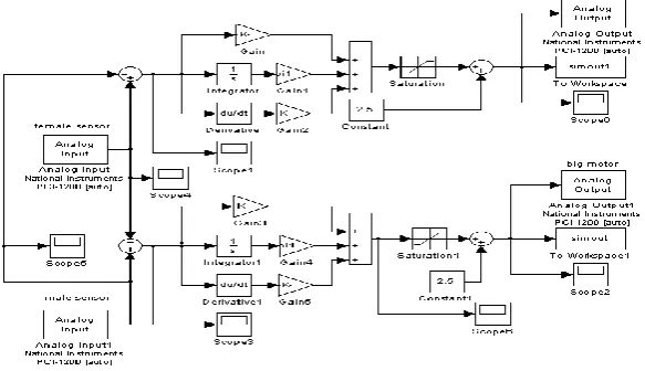
3.1.1.8 Simulink Modeling
Most of the modeling and control is done using SimuLink and Matlab . The Real-Time Workshop in Simulink
llows the user to design the controller in blocks and then compiles the scheme an drums the program in real-time
as long as the computer is on. As opposed to past years, when the DAQ Board could only be used for a limited
number of data samples (and therefore time), the Real-Time Workshop is a huge improvement. In the
steer-by-wire system, I implement the model seen in Figure 11. Although the controls of both motors seem similar, their
inherent differences require different control parameters. The input to both controllers is governed by the rrence
in the rotary sensor readings. In other words, the error signal is the difference in the angular sensor voltages.
Both systems use PID controllers but the parameters vary. Also, since integration causes more noise, the
integration constant is very low. Because the steering wheel angle sensor and the pinion angle sensor will
usually be very close to each other, the integral control component does not help the system very much. In
Figure 11, you can see that the output of the PID goes through a saturation and a constant of 2.5 is added after
the saturation. This is because both motors are at rest when the inputs are 2.5V and they work in the range of 0–
5V. The saturation adjusts the voltage to a range of -2.5–2.5Vand the addition of 2.5V puts the final controller
output in a range of 0–5V.
3.1.1.9 Computer Modeling
Alhough the control system can be done in hardware, it is much easier to implement the control system in
software. I chose to use Matlab because I was familiar with it from previous classes. There were some
simulations of steer-by-wire systems done using Matlab[4] so I knew it would be a great choice.
Figure 11: Control model
IV. TESTING
4.1 Testing Procedure
Once I implemented my system with all individual parts working, I had to find optimal constants for the PID
controller and adjust the saturation levels of the PID output. First I tested each motor individually, and observed
their behavior for step inputs. I saw that the steering motor was very slow and that the controller output would
be at a maximum (or minimum for reverse) most of the time. On the other hand, the feedback actuator would
spin very fast with controller outputs of 5V or 0V, so I adjusted the saturation levels to -0.75–0.75V. With this
317 | P a g e
and a fast response.Since the controller output was saturated most of the time, I did not do simulations on the
computer, and instead I found the PID constants by trial and error. However this did not mean that I would have
to rely on my luck to find the right values. Since I was familiar with the effects of changing control parameters, I
could reach good values pretty soon and build on them.
4.2 Determining PID constants
There are a few tuning methods to find the constants (or get in the ballpark of good constants). I first used the
Ziegler-Nichols method introduced by John G. Ziegler and Nathaniel B. Nichols. Thismethod starts with finding
a critical gain Kc (the gain for which a proportional controller usingthis gain starts to oscillate). Then at the
oscillation frequency it finds the oscillation period, Pc.Then the Ziegler-Nichols method suggests the values
seen in Table 1.
Parameter Kp Ki Kd
Value 0.6Kc Pc/2 Pc/8
Table 1: PID controller constants using the Ziegler-Nichols method
Initially, this gave me some guidance, and I had some success with controlling each of the motorsindividually,
but I noticed that when I put the two systems together, these parameters did not helpme much. The feedback
actuator would vibrate a lot especially because the steering motor was veryslow in reacting. I noticed that if I
held the steering rod in place and waited for the steering motorto approach its desired position, the integral
control would increase the output to the feedbackactuator too much, and releasing the steering rod would cause
it to overshoot a lot. When thesystem was in equilibrium, small differences in the sensor angles caused
vibrations in the feedbackactuator so eventually, I opted to eliminate the integral component of the feedback
motor.The steering motor controller was very slow in switching from maximum forward to maximumreverse
direction, so the control of the motor was very hard. When I was deciding the PID constants,I noticed that all
combinations pretty much gave similar results. In the end, I decided to use valuesfor which the step response
would cause the motor controller to switch in time to drive the motorin the opposite direction and stop it. In
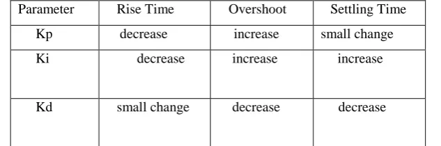
general I followed the guideline in Table 2 to achieveacceptable controller constants. The final values I used can
be found in Table 3
Parameter Rise Time Overshoot Settling Time
Kp decrease increase small change
Ki decrease increase increase
Kd small change decrease decrease
318 | P a g e
Table 3: PID controller values for the final design
V. ADVANTAGES
1 .No steering column – Simplify the design of a car’s interior, giving the driver more space as well as better
safety in case of a crash (no intrusion of the steering column).
2. The absence of steering shaft and gear reduction mechanism allows much better utilization of the engine’s
compartment.
3. Decreases the total weight of the car issuing better energy reduction effectiveness.
4. Easier implementation of left or right-hand driving.
5. No noise or vibration can reach the driver’s hands.
6. The most significant benefit is the ability to electronically augment the driver’s steering input depending of
drive’s conditions, also called active steering.
VI. LIMITATIONS
Pneumatic trail, a function of slip angle, is linear for small angles
Non-linearity problem for bigger angles
Linearization of friction in steering block
VII. DISCUSSION
Although there were many problems I encountered with each part of the project, in the end, I wasable to show
that a steer-by-wire system could work. However, given the slow responses of thesystem, my setup is far from
ideal and needs many improvements. The feedback motor workedvery well and to a certain extent it simulated
the real driving experience. The steering motordidn’t work very well at all, and this can be attributed to the
characteristics of the motor and themotor controller. The motor controller had a very slow switching time. It
would take about 0.4seconds to switch from one direction to the other and this really hindered the operation.
Also, thesteering motor was quite powerful so even though the motor controller were able to switch veryfast, the
motor would still be slow to react. In a real implementation, it might be a good idea to usetwo dedicated motors,
one for each direction. The steering wheel can also be improved by addingdampers and springs.I believe that
with various improvements, steer-by-wire can achieve some success. Sometimeseven very small delays in
reaction can be fatal so the delay between steering wheel rotation andactual steering might pose a great threat in
the development of SBW systems. However, given other advancements in automotive technology, we see that
more and more AI systems are be ingintegrated into cars and combining SBW systems with these can be very
promising. Doinng this project has improved my understanding of control systems greatly and I havegained steering motor feedback actuator
Kp 0.5 0.65
Ki
0.05 0
319 | P a g e
significant experience in combining electronic and mechanical systems. Although I have note accomplished my
initial goals of the project 100%, I believe that there was a lot of progress madeand I think that this system can
be improved upon.
VIII. FUTURE WORK
The SBW system I build can be improved a lot, but the main problem seems to be with thechoice of controllers
and motors. For a future project, given better equipment, this system couldbe implemented in a small model car
and can be used for control theory demonstrations. Newcontrol systems, such as state-space controls, can be
implemented to enhance the performance ofthe system.Although not in the near future, given enough resources,
this system can be implemented in real road cars and perhaps be combined with regular steering to take
advantage of the safety benefits ofa steer-by-wire system.
ACKNOWLEDGEMENTS
I would like to thank my advisor for his invaluable help with the project.Without his guidance, patience and
encouragement, this project would never be complete. I wouldalso like to thank Prof. Fred Orthlieb, Grant
Smith, Ed Jaoudi, AronDobos, Danielle Miller and Emily Kan with their guidance and help with mechanical
parts of the project. I would like tothank Prof Bruce Maxwell and Prof Cheever for all the engineering classes I
took with them (a lot).Finally, I would like to thank all fellow Swarthmore Engineers for being the people they
are.
REFERENCES
[1] Newlaunch.com. Steer-by-wire concept cars exhibited at tokyo motor show.
[2] Kassakian Dominguez-Garcia. Haptic interface for automotive steer-by-wire systems.
[3] Jon DemerlySanketAmberkar, FarhadBolourchi and Scott Millsap. A control system methodologyfor steer
by wire systems.
[4] Joachim Langenwalter and Tom Erkkinen. Model-based design with production code generationfor