52 |
P a g e
TAGUCHI ANALYSIS OF FORGING DEFECTS FOR
GEARS
1
Vipan Chand ,
2Dr.S.S.Sen,
3M.S.Sethi
1
PG Student, Deptt. Of Mech. Engg., G.H.E.C ,Solan(India)
2
Principal G.H.E.C ,Solan(India)
3
HOD, Deptt. Of Mech. Engg.,G.H.E.C, Solan(India)
ABSTRACT
Forging is a metal forming process commonly used in industry. Forging process is strongly affected by the
process temperature. In hot forging process, a wide range of materials can be used and even complex geometries
can be formed. However in cold forging, only low carbon steels as ferrous material with simple geometries can
be forged and high capacity forging machinery is required. Warm forging compromise the advantages and
disadvantages of hot and cold forging processes. In warm forging process, a product having better tolerances
can be produced compared to hot forging process and a large range of materials can be forged compared to cold
forging process.
In this study, forging of a particular part which is being produced by hot forging at 1200°C for automotive
industry and have been made of carbon steel, is analyzed by optimization of the forging parameter. Study has
been conducted for the same temperature range in a forging company. A good agreement for the results has been
observed.
Keywords: Hot Forging, Metal Forming, Forging temperature
I. INTRODUCTION
This chapter deals with the introduction to forging and its processes, followed by motivation of the research work and ends with research plan.
Forging and its historical aspects
The term “forging” is applied to processes in which a piece of metal is worked in a machine to the desired shape by plastic deformation of the starting stock. It is also known as a secondary manufacturing process, which converts the products from the primary operation into semi-finished or finished parts. During forging, metal is compressed under high pressure to form the desired shape products. The deformation it undergoes gives the forged parts superior mechanical properties by aligning material’s structure along the direction of deformation,
53 |
P a g e
such as bronze and wrought iron were forged by early man to produce hand tools and weapons of war. Forging of wrought iron and crucible steel continued until near the end of the 19th century for similar purposes and weapons of war are still produced by the forging process using more contemporary metals. The forge-smiths of the 19th century were particularly skilled at hand or by open die forging of wrought iron. As compared to casting, forging is stronger and has a better response to heat treatments.
As compared to machining, forging has a wider size range of desired material grades and a preferable grain orientation along surface; besides, forging makes a better use of materials with the material savings as great as 75% compared to machining. Economically, forged products are attractive because of their inherent superior reliability, improved tolerance capabilities, and the higher efficiency with which forgings can be machined and further processed by automated methods. The structural reliability in forging is unexcelled by any other metalworking process. There are no internal gas pockets or voids that could cause unexpected failure under stress or impact. Often, the forging process assists in improving chemical segregation of the forging stock by moving centreline material to various locations throughout the forging.
II. CURRENT STATUS OF RESEARCH
Studies have been conducted on establishing the forging defects die wear analysis and determining the various
process parameters. The surface defects were studied. The optimization technique used and the various analyses
were carried out by using the FEA analysis. Most of the work is carried out in hot forging. Some work was also
carried out in gear manufacturing. This chapter illustrates the review of the earlier work done on the proposed
topic.
Christry Mathew, et.al.[1] The study is focused on the forging analysis of an integral axle arm produced by
hot forgings are made. Forging analysis is done to explain that how the defects occur and how to prevent them.
With the help of Pareto diagram, this is mostly used to identify major areas. Then the cause and effect diagram
is used to explore possible causes of defects through a brainstorming session and to determine the causes which
have the greatest effect. Corrective measures are being suggested to overcome the forging defects of the
integral axle arms. Finally, few remedial measures and suggestions have been provided for the existing integral
axle arm production process in the forging shop.
Aju Pius, Sijo.[2] The author studied and investigate the various forging defects that occur in a forging
industry that causes high rejection rates in the components and remedial measures that can reduce these
defects in the hot forging. The investigation was done with the help of quality assurance department within
the industry. The result indicates that the rejection rate in the company was more than five percent of the total
productions made each month. The defects in the forged components includes the lapping, mismatch, scales,
quench cracks, under filling etc. The remedial actions includes the proper use of anti scale coating, venting
process to prevent the under filling, the simulation software for determining the material flow, proper lubricant
instead of furnace oil etc.
Yang and Nagil.[3] The author studied the multi-stage forging processes to ensure the production of defect-free
54 |
P a g e
preform shapes could be difficult and time consuming. In his paper proposes an efficient preform design
methodology based on geometrical resemblance, which requires several finite element analysis simulation
iterations to obtain a good perform shape. In order to verify this perform-design methodology, several case
studies on forging and extrusion processes have been carried out.
Md.Israr Equbal, et.al.[4] The study focused on to improve the forging quality and decreasing the production
cost. The objective of this study is to obtain an optimal perform shape in the consideration of the influence of
the metal flow deformation in closed die forging process. Taguchi method has been used to simulate the
closed die forging process and then performing a series of optimization iterations in order to obtain the optimal
shape of the billet based on forging load minimization. The goal of the simulation and optimization process is to
minimize the forging load and produce defect-free forgings. The optimal shape of the billet that gives minimum
forging load with complete die filling was obtained after several optimization iterations.
Banaszek and Stefanik.[5] The author studied hot forging of anvil shape in laboratory modelling of the process
of free hot forging in shaped anvils was conducted to the closure of metallurgical defects.Results obtained from
the simulation and laboratory modelling were processed by using a commercial statistical package, Statistica
6.0®PL. The influence of the anvil shape and main parameters of the forging process on closure of metallurgical
defects were determined. On the basis of the investigation carried out, the optimal values of the main forging
technological parameters of and suitable groups of anvils to be used in particular forging stages are proposed for
the elimination of metallurgical defects.
M.Poursina et.al[6] Since 1980s the problem of manufacturing defect-free parts has been tackled with
simulation tools. In this paper, a numerical method for shape optimisation of pre-form dies in a two-stage hot
forging is presented. The object of optimisation is to eliminate work-piece defects that may arise during the
forging process. A two dimensional finite element code has been developed for the simulation of the mechanical
process and prediction of the defects. The material is incompressible and it follows the Norton–Hoff law. To
deal with contact constraint, the velocity-projection algorithm is used. The optimisation method is based on a
genetic algorithm supported by an elitist strategy. The developed scheme is used to design optimal pre-form dies
for two axi-symmetric examples. The objective function is associated with the quality of the final product.
Comparing the obtained optimal results with other articles justifies the proposed optimisation method.
T.Ishikawa, N.Yukawa, Y.Yoshida and Y.Tozawa.[7] In this study, the elimination of surface
micro-defects in forging is studied. The finite element analysis featuring effective meshing and an adaptive remeshing
system is applied. V-shaped and rectangular scratches on the surface of billet are simulated under the
axisymmetric assumption and the basic deformation of scratch during upsetting and the influence of friction on
the deformation of micro-defects are discussed. During upsetting the shallow V-shaped scratch on the top
surface of billet tends to disappear and deep scratch becomes lap. Defects are more likely to disappear under low
55 |
P a g e
F. R. Biglari, and M Zamani. [8] In this study, the wear profile on the die surface during the hot forgingoperation for an axisymmetric cross-section is examined. The amount of wear is calculated for two wear models
by implementing a rigid thermo-viscoplastic finite element analysis into the metal forming process. The first
model consists of the classical model which proposes that the amount of the wear is proportional to the die
pressure and sliding length. The second model assumes that the wear is proportional to the energy dissipated on
the tool/workpiece contact interface. The influence of the friction on the amount of die wear and the material
flow is discussed. It was concluded that the increase of friction coefficient does not enhance the die wear in
general.
M.T.Khaleed Hussain, Z.Samad, A.R.Othman, and S.C.Pilli.[9] This paper gives a review of optimization of
cold forging die design and dies design process, which has been done by many authors using different
techniques. The fatigue behavior and fatigue failure of the die when it under go cyclic loading is studied. The
study concluded with future challenges of the die design and its processes, the approaches adopted to develop an
optimum system that can fulfill the customer demand.
Sung-Woo Bae and Yohng-Jo Kim.[10] In this study the design of die shapes for the forging process of a
hollow flange, computer simulations were carried out using the rigid-plastic finite element method. Forging
defects like folding were seen in the vicinity of die corners at the typical shape ratios of upper and lower dies.
Die shape ratios at which the forging defect could occur during the extrusion-forging process of the hollow
flange were investigated.
M. Mirsaeidi, F.R.Biglari, K.Nikbin and E.Moazami Goudarzi.[11] In the present study, a new method for
forging preform design has been developed based on linear interpolation technique. The use of preform shapes
obtained by this technique would result in enhancement of the geometrical and mechanical quality of final part.
Among the obtained preform shapes the one preform that gives more uniform accumulated equivalent plastic
strain. Using plasticine as an ideal material to validate the findings it is shown that by the use of this optimum
preform shape, the geometrical defects such as under filling and fold over defects may be eliminated in the final
product.
III. EXPERIMENTATION
Process optimization and Taguchi method
Statistical methods are commonly used to improve the quality of a product or process. Such methods enable the
user to define and study the effect of every single condition possible in an experiment where numerous factors
are involved. Defect analysis is such a process in which a number of control factors collectively determine the
56 |
P a g e
method is used to optimize the process parameters leading to minimum defect during forging process of gear
and axle shaft under study.
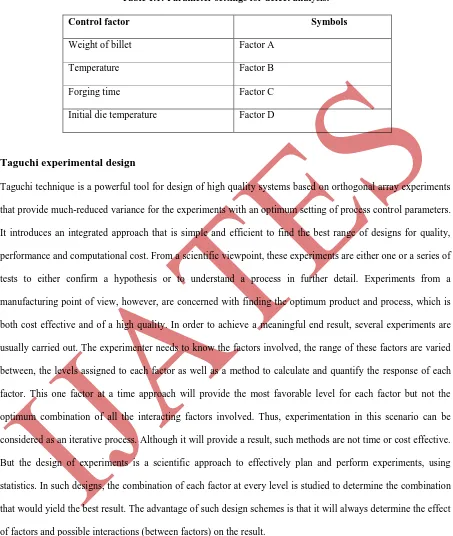
Table 1.1: Parameter settings for defect analysis.
Control factor Symbols
Weight of billet Factor A
Temperature Factor B
Forging time Factor C
Initial die temperature Factor D
Taguchi experimental design
Taguchi technique is a powerful tool for design of high quality systems based on orthogonal array experiments
that provide much-reduced variance for the experiments with an optimum setting of process control parameters.
It introduces an integrated approach that is simple and efficient to find the best range of designs for quality,
performance and computational cost. From a scientific viewpoint, these experiments are either one or a series of
tests to either confirm a hypothesis or to understand a process in further detail. Experiments from a
manufacturing point of view, however, are concerned with finding the optimum product and process, which is
both cost effective and of a high quality. In order to achieve a meaningful end result, several experiments are
usually carried out. The experimenter needs to know the factors involved, the range of these factors are varied
between, the levels assigned to each factor as well as a method to calculate and quantify the response of each
factor. This one factor at a time approach will provide the most favorable level for each factor but not the
optimum combination of all the interacting factors involved. Thus, experimentation in this scenario can be
considered as an iterative process. Although it will provide a result, such methods are not time or cost effective.
But the design of experiments is a scientific approach to effectively plan and perform experiments, using
statistics. In such designs, the combination of each factor at every level is studied to determine the combination
that would yield the best result. The advantage of such design schemes is that it will always determine the effect
of factors and possible interactions (between factors) on the result.
Taguchi design of experiment is a powerful analysis tool for modeling and analyzing the influence of control
factors on performance output. The most important stage in the design of experiment lies in the selection of the
control factors. Therefore, initially a large number of factors are included so that non-significant variables can
57 |
P a g e
(313) orthogonal design. The operating conditions under which defect analysis is carried out for gear and axle
shaft are given in Table 1.2.
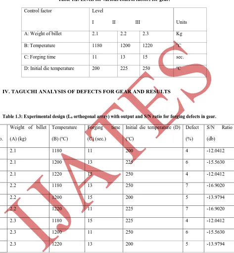
Table 1.2: Levels for various control factors for gear.
Control factor Level
I II III Units
A: Weight of billet 2.1 2.2 2.3 Kg
B: Temperature 1180 1200 1220 oC
C: Forging time 11 13 15 sec.
D: Initial die temperature 200 225 250 oC
IV. TAGUCHI ANALYSIS OF DEFECTS FOR GEAR AND RESULTS
Table 1.3: Experimental design (L9 orthogonal array) with output and S/N ratio for forging defects in gear.
S.
No.
Weight of billet
(A) (kg)
Temperature
(B) (oC)
Forging time
(C) (sec.)
Initial die temperature (D)
(oC)
Defect
(%)
S/N Ratio
(db)
1. 2.1 1180 11 200 4 -12.0412
2. 2.1 1200 13 225 6 -15.5630
3. 2.1 1220 15 250 4 -12.0412
4. 2.2 1180 13 250 7 -16.9020
5. 2.2 1200 15 200 5 -13.9794
6. 2.2 1220 11 225 7 -16.9020
7. 2.3 1180 15 225 4 -12.0412
8. 2.3 1200 11 250 6 -15.5630
58 |
P a g e
2.3 2.2
2.1 -13
-14
-15
-16
1220 1200
1180
15 13
11 -13
-14
-15
-16
250 225
200 Weight of billet
M
e
a
n
o
f
S
N
r
a
ti
o
s
Temperature
Forging Time Initial Die Temperature
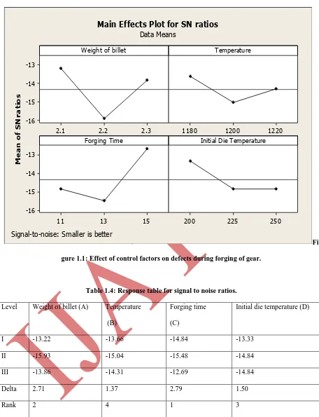
Main Effects Plot for SN ratios
Data Means
Signal-to-noise: Smaller is better
Fi
gure 1.1: Effect of control factors on defects during forging of gear.
Table 1.4: Response table for signal to noise ratios.
Level Weight of billet (A) Temperature
(B)
Forging time
(C)
Initial die temperature (D)
I -13.22 -13.66 -14.84 -13.33
II -15.93 -15.04 -15.48 -14.84
III -13.86 -14.31 -12.69 -14.84
Delta 2.71 1.37 2.79 1.50
59 |
P a g e
References[1] M. Christry, K. Justin, V. Deviprasd. Study of forging defects in integral Axle Arms. International Journal
of Engineering and Innovative Technology, 2013: 2-7.
[2] A.P. Thottungal, M.T. Sijo. Controlling measures to reduce rejection rate due to forging defects.
International Journal of Scientific and Research Publication, 2013: 2-3.
[3] C. Yang, G. Nagail. Perform design for forging and extrusion processes based on geometrical resemblance.
Journal Mechanical manufacturing, 2009; 224: 1409-1423.
[4] M.I. Equbal, R.K. Ohdar. Preform shape optimization of connecting rod using finite element method and
Taguchi method. International Journal of Modern Engineering Research, 2012; 2: 4532-4539.
[5] G. Banaszek and A. Stefanik. Theortical and laboratory modeling of the closure of metallurgical defects
during forming of a forging. Journal of Material Processing Technology, 2006: 238-242.
[6] M. Poursina, J. Parvizian. Optimum pre-form dies in two- stage forging. Journal of Material Processing
Technology 2006: 325-333.
[7] T. Ishikawa, N. Yukawa, Y. Yoshida, Y. Tozawa. Analytical approach to elimination of surface
micro-defects in forging.CIRP Annals Manufacturing Technology, 2005; 54(1): 1-4.
[8] F.R. Biglari, M. Zamani. Die wear profile investigation in hot forging. Proceedings of the World Congress
on Engineering, 2008; vol. II: 3-7.
[9] H.M. Khaleed, T. Samad, A.R .Othman, S.C. Pilli. A study on cold forging die design using different
techniques. CCSE Modern applied science, 2003; 3(3): 143-154.
[10]S.W. Bae, Y.J. Kim. Rigid-plastic finite element analysis for forging process design of a hollow flange.
Journal of the Korean Society of Manufacturing Process Engineers, 2004; 3(1): 59-65.
[11]M. Mirsaeidi, F.R. Biglari, K. Nikbin, E. Moazami, Goudarzi, S. Bagherzadeh. Optimum forging preform
shape design by interpolation of boundary nodes. Proceedings of the World Congress on Engineering, 2009;