Jamming Mitigation by Randomized Bandwidth
Hopping
Marc Liechti
ETH Zurich
Zurich, Switzerland
marc@
liechti.one
Vincent Lenders
armasuisse
Thun, Switzerland
vincent.lenders@
armasuisse.ch
Domenico Giustiniano
IMDEA Networks Institute
Madrid, Spain
domenico.giustiniano@
imdea.org
ABSTRACT
We present bandwidth hopping spread spectrum (BHSS), a novel technique to improve the jamming resistance of wire-less communications. In BHSS, the bandwidth of a signal is hopped rapidly in a manner that is unpredictable to the jammer. We show in this work that by combining band-width hopping at the transmitter with adaptive filtering at the receiver, BHSS is able to improve the jamming resis-tance of the communication beyond the processing gain of conventional spread spectrum techniques such as DSSS and FHSS without an increase in RF spectrum requirements. We have designed and implemented a BHSS transmitter and re-ceiver system on off-the-shelf software-defined radios. Our experimental results with different hopping patterns show that BHSS is able to boost the power advantage of spread spectrum communication by8to20dB for jammers of fixed bandwidth. When both transmitter and jammer hop randomly, the average power advantage we achieve with our system is
11.4dB.
CCS Concepts
•Security and privacy → Mobile and wireless security;
•Networks→Wireless access networks;
Keywords
Wireless security, Jamming resistance, Bandwidth hopping, Interference filter, Spread spectrum, Software-Defined Ra-dio.
Permission to make digital or hard copies of all or part of this work for personal or classroom use is granted without fee provided that copies are not made or distributed for profit or commercial advantage and that copies bear this notice and the full citation on the first page. Copyrights for components of this work owned by others than ACM must be honored. Abstracting with credit is per-mitted. To copy otherwise, or republish, to post on servers or to redistribute to lists, requires prior specific permission and/or a fee. Request permissions from [email protected].
CoNEXT ’15, December 01-04, 2015, Heidelberg, Germany © 2015 ACM. ISBN 978-1-4503-3412-9/15/12. . . $15.00
DOI:http://dx.doi.org/10.1145/2716281.2836096
1.
INTRODUCTION
Spread spectrum (SS) communication is a technique in which the bandwidth of the transmitted waveform is inten-tionally made wider than would be necessary to transmit the information over the channel. SS was originally developed to resist jamming attacks in military environments. However, nowadays, SS is also wide-spread in other civilian communi-cations systems such as low-power sensor networks, WLAN, global navigation satellite systems, and unmanned aerial ve-hicle (UAV) control systems.
There exist two common spread spectrum techniques: di-rect sequence spread spectrum (DSSS) and frequency hop-ping spread spectrum (FHSS). To mitigate the interference in DSSS, the transmitter spreads a low bit-rate information signal to a wider spectrum of fixed width by multiplying the signal with a higher bit-rate pseudorandom spreading chip sequence. In FHSS, the transmitter randomly hops the car-rier frequency of the modulated signal. This has the effect of spreading the signal bandwidth over a wider band than actu-ally occupied by the information bandwidth. The demodula-tion operademodula-tion in SS has the effect of mitigating the amount of interference power to a fraction that is proportional to the ratio between the spreading chip band (DSSS)/hopping band (FHSS) to the actual signal bandwidth, which is the so-called processing gain.
In theory, any level of jamming rejection can be achieved in DSSS or FHSS by using sufficient processing gain, i.e., by spreading the signal to an arbitrarily large bandwidth. For example, military communication systems may be us-ing spreadus-ing factor up to 1000 [1, 2] to achieve processus-ing gains in the order of30dB. However, the wireless spectrum is a scarce resource today and allocating that much spectrum for achieving jamming resistance is generally not desired or even impossible in non-military contexts, given the through-put requirements of current communication systems.
Signal BW BS
Frequency
P
ow
er
spect
ral
de
ns
ity
Jammer BW BJ
Signal BW BS
Frequency Excision filter
Excision filter
P
ow
er
spect
ral
de
ns
ity
p p
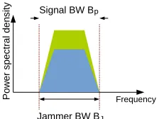
Figure 1: The jammer bandwidth is smaller than the sig-nal bandwidth. Applying an excision filter removes the signal power of the jammer.
6, 7]. While highly effective at suppressingunintentional narrow-band interference, excision filters as such fail to re-sist againstmaliciousjamming attacks. A malicious jammer can observe the signal bandwidth as being transmitted over the air and match his jamming waveform to the bandwidth of the signal rendering any excision filtering ineffective. The jamming resistance of SS in adversarial conditions has there-fore been considered up to now as being equal to the process-ing gain of the system [1, 2, 8, 9].
In this paper, we show in contrast that it is possible to im-prove the jamming resistance in adversarial settings beyond the processing gain of traditional SS communication. The new concept we propose in this work is toquickly hop the SS signal bandwidth according to a randomized hopping pat-tern that is known to the receiver, but unpredictable to the adversary. In other terms, we explore the bandwidth as a new dimension that complements the chip and frequency do-mains for jamming-resilient communications. When the sig-nal bandwidth is hopping fast enough such that the jammer cannot react quickly enough to the current bandwidth being transmitted, it is no longer possible for the jammer to match its bandwidth to the one of the transmitter.
Depending on the transmitter-jammer bandwidth offset, we can then differentiate three fundamental cases: (i) The signal widthBpis wider than the interfering jammerBj (Fig-ure 1). The jammer’s interference appears as narrow-band and it can thus be suppressed at the receiver effectively with an excision filter prior despreading. (ii) The jammer signal is wider than the communication signal (Figure 2). The re-ceiver can low-pass filter the received signal in baseband and hence remove the signal power of the jammer that is outside the signal spectrum. (iii) The interference has the same width as the signal (Figure 3). In the latter case, the receiver is left with the entire interference of the jammer when despreading the signal and the resistance is equal to the processing gain of traditional SS techniques. However, when the signal band-width is constantly hopping, the likelihood that the jammer bandwidth matches the one of the transmitter by chance is low and this case therefore rarely occurs.
While the idea of dynamically adapting the signal band-width in wireless communications has also been suggested recently in [10, 11], the hopping requirements for achieving jamming resistance impose new challenges that we address in this work:
Filter Frequency
P
ow
er
spe
ct
ral
den
si
ty
Jammer BW BJ
Filter P Filter Frequency
ow
er
spect
ral
de
nsi
ty
Filter
Jammer BW BJ
Signal BW BSp Signal BW BpS
Figure 2: The jammer bandwidth is larger than the sig-nal bandwidth. Applying a low-pass filter removes the power of the jammer that is outside the bandwidth of the communication signal.
Signal BW BS
P
ow
er
spe
ct
ral
den
si
ty
Frequency
Jammer BW BJ
p
Figure 3: The signal and the jammer bandwidth are the same. The power of the jammer cannot be filtered out. When the signal bandwidth is constantly hopping, the likelihood that the jammer bandwidth matches the one of the transmitter by chance is low and this case there-fore rarely occurs.
1. The signal bandwidthBpmust be adapted quickly when the radio is active during the transmission of individual packets. This is necessary to resist to modern reactive jammers [12] that are capable of following signals with reaction delays below packet transmission times. In contrast, existing communication schemes proposed in the literature operate at much coarser granularities and adapt the signal bandwidth between packet transmis-sions when the front-end radio is idle.
2. Previous works endorsed dynamic signal bandwidths having data throughput as primary objective. These works therefore do not address the issues of making the hopping pattern unpredictable and robust to jam-mers and to filter out interference at the receiver prior despreading in order to improve the jamming resistance beyond the processing gain of SS.
Our main contributions in this paper are:
● We propose bandwidth hopping spread spectrum (BHSS) as a technique to improve the jamming resistance be-yond the processing gain of SS communication sys-tems. In contrast to other jamming mitigation tech-niques [13, 14], BHSS improves the jamming resis-tance in communications systems that operate with a single omnidirectional antenna at the transmitter and receiver.
sig-nals while actively transmitting, i.e. the bandwidth is hopped during the transmission of individual packets.
● We analytically derive the general SNR improvement of a BHSS receiver for different bandwidth offsets be-tween transmitted and jamming signals. We evaluate the bit error rate and throughput of a BHSS receiver and compare those to the performance of conventional DSSS and FHSS receivers.
● We implement a bandwidth hopping transmitter and receiver on software defined radios and demonstrate the improved jamming resistance for different hopping patterns.
2.
SYSTEM AND ATTACKER MODEL
We consider a scenario in which a transmitter wants to send data to a receiver over the wireless channel. This com-munication could be for example between a ground station and a UAV. The attacker is a jammer that wants to disrupt the wireless communication between the transmitter and the receiver.
The jammer is assumed to be in transmission range of both the transmitter and the receiver, so that he can overhear the signals from the transmitter as well as interfere with its own signals at the receiver. For this, the jammer may rely on half duplex or full duplex radios [15]. Regardless of the radio type, we assume that the jammer has reactive capabilities, i.e., the jammer can sense the channel and interfere with a signal based on the sensed channel information. Reactive jamming is a relatively strong attacker model, however it has been shown to be a realistic threat model as it is possible to implement such a jammer using commercial off-the-shelf (COTS) hardware only [12].
We assume the jammer reaction time to be lower-bounded. We denote the time difference between the arrival of the orig-inal signal and the jammer signal at the receiver as the jam-ming reaction time τ. The minimal reaction time τmin is bounded by the sum of (i) the signal propagation delay be-tween the sender and the jammer, (ii) the hardware and soft-ware reaction delay of the jammer to process the incoming signal and to make a jamming decision, and (iii) the signal propagation delay between the jammer and the receiver. It is therefore safe to assume that the minimum reaction time τminis greater than the duration of a couple of bits or sym-bols [12].
Both the legitimate transmitter and the jammer are assumed to have infinite energy but limited transmission power bud-get. The jammer can thus interfere with any signal waveform and an arbitrary signal bandwidth, as long as it does not ex-ceed its power budget. In order to attack a SS system that is not hopping the bandwidth, the jammer may therefore sense the bandwidth of the signal sent by the transmitter and react with an additive white Gaussian noise (AWGN) signal that interferes at the receiver with the same bandwidth as the tar-get signal. The mere application of excision filters without dynamically hopping the bandwidth of the signal is there-fore ineffective at mitigating the impact of jamming under the considered reactive attacker model.
Random seed
PN sequence
Symbol DSSS
Spreading Chip
Chip
Spreading DSSS Symbol
PN sequence Bandwidth
Pulse
Pulse I/Q
I/Q Random seed
DSSS transmitter
Shapingg(t)
Shapingg(αt) BHSS/DSSS transmitter
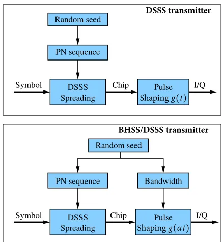
Figure 4: Comparison between conventional DSSS block scheme and block scheme of BHSS. In BHSS, the pulse shape is not constant but randomly changed to produce spread signals of different bandwidths. BHSS can analo-gously be applied to FHSS.
3.
BANDWIDTH HOPPING
TRANSMIT-TER
The novel concept we propose in this work is to hop ran-domly the bandwidth of the signal in a manner that is un-predictable to the jammer. Wireless communication systems have traditionally been designed with fixed signal bandwidths. Some more recent systems support adaptive signal bandwidths, but the bandwidths are not switched in the same way as pro-posed in this work. For example in [10], the authors propose SampleWidth, an algorithm that samples the channel con-ditions and dynamically switches between different band-widths. However, the bandwidth is switched at the MAC layer when the experienced packet error rate or SNR drops below a certain value in order to move to more robust rates. Since the rate switching occurs at the MAC, the hopping be-tween different bandwidths is too slow to protect against a reactive jammer that tries to match its bandwidth to the sig-nal bandwidth of the sigsig-nal. As shown in [12], reactive jam-mers are able to estimate signals over the air and generate matched jamming signals in the order of a couple of sym-bols. To thwart reactive jammers, it is therefore necessary to hop the bandwidth dynamically at the PHY layer by chang-ing the bandwidth durchang-ing the transmission of the signal.
I-Channel Q-Channel
S
ig
na
l
A
m
pl
itu
de
time
f f
f f
S
pe
ct
ra
l
D
en
si
ty
Figure 5: Signal waveform and bandwidth of a BHSS signal whose bandwidth is hopped dynamically during a transmission.
mapped to symbols and then chips by multiplying the sym-bols with a pseudo-noise (PN) sequence. This corresponds to the spreading operation of DSSS. The PN sequence is ini-tialized with a random source to make the chip sequence un-predictable to the jammer. Each chip is then modulated with a pulse shapeg(t), whose shape is depending on the modula-tion scheme. The difference between the convenmodula-tional DSSS transmitter and BHSS is visible at the bottom of Figure 4. Instead of using a constant pulse shape g(t), we vary the shape of the pulse by scaling its duration with a factor α. The value ofαis chosen randomly using a random seed and changed after a fixed number of symbols. By randomly vary-ing the pulse shape duration, we produce modulated signals of different bandwidths that are unpredictable to the jammer. Stretching a signal in the time domain withαhas the effect of reducing the signal width in the frequency domain by the same factor, and viceversa:
g(t)Ð→F G(ω) Ô⇒g(αt)Ð→F ∣α1∣G(ωα) (1)
whereF indicates the Fourier transform. Using this tech-nique, the signal bandwidth can be adapted to any desired bandwidth without interrupting the signal transmission. An example of the signal waveform and bandwidth over four hops is shown in Figure 5. As we see in the top of the Figure, the pulse shape duration is first decreased and then increased twice. This produces a signal whose bandwidth in baseband is hopping as illustrated in the bottom of Figure 5. In the presence of jamming, the goal of the BHSS transmitter is therefore to hop according to a strategy that minimizes the bit error rate, while guaranteeing a sufficiently high commu-nication rate.
4.
BANDWIDTH HOPPING RECEIVER
The receiver has to face two main challenges to decode the data transmitted by the bandwidth hopping transmitter:
(i) It must acquire a signal whose bandwidth is hopping during a transmission with a random pattern.
(ii) The acquired signal will further include the superim-posed interference generated by the jammer which needs to be estimated and filtered by the receiver.
PN sequence DSSS Despreading
Chip Symbol
Demod I/Q
LPF
EF
I/Q I/Q De
mod
Chip Symbol
Despreading DSSS
Bandwidth PN sequence
Control logic
Random seed Random seed
DSSSreeiver
BHSS/DSSSreeiver
Figure 6: Comparison between conventional DSSS re-ceiver and BHSS rere-ceiver. In BHSS, the demodulator is synchronized to the bandwidth of the signal and a control logic estimates and configures filters to suppress interfer-ence prior sending the I/Q samples to the demodulator. In the figure, LPF stands for low pass filter and EF for excision filter.
In order to address (i) and (ii), we introduce our receiver structure to synchronize to the signal bandwidth (Section 4.1) and suppress the interference of the jammer for different band-width offsets between the signal and the jammer (Section 4.2).
4.1
Bandwidth Synchronization
Conventional SS systems operate at fixed signal bandwidths. The DSSS and FHSS receivers therefore need only to syn-chronize to the PN sequence or the frequency hopping pat-tern for the despreading operation. For example, the receiver block structure for DSSS is shown at the top of Figure 6. The receiver first demodulates the chips from the received I/Q samples. Then, the symbols are despread by correlating the received chip sequence with a replica of the synchronized PN sequence. The PN sequence is synchronized to a ran-dom seed at the receiver. Ranran-dom seed synchronization be-tween transmitter and receiver can be done in different ways. The most common techniques rely on pre-shared keys [16] or through uncoordinated discovery schemes [17]. In this work, we assume that such a random source synchronization mechanism already exists since it is present in any SS sys-tem.
with FFT). However, this approach is not robust to jamming scenarios because the instantaneous bandwidth of the incom-ing signal may be dominated by the jammer for strong jam-ming powers. We therefore suggest instead to rely on the same random source as for the synchronization of the spread-ing operation in DSSS or FHSS. That is, we derive the in-stantaneous bandwidth at the receiver from the synchronized random source as shown at the bottom of Figure 6.
4.2
Jammer Estimation and Filtering
The main difference between a conventional SS receiver and our bandwidth hopping receiver is that we estimate and suppress the jammer prior despreading the signal. For this, the BHSS receiver includes a control logic that controls the configuration of a low-pass filter (LPF) and an excision fil-ter (EF) prior demodulation as shown in Figure 6. This will result in an improvement of the jamming resistance beyond the processing gain of the despreading operation. In order to select an appropriate filter to suppress the jamming in-terference prior despreading, a control logic estimates the frequencies occupied by the jammer. A convenient way to do so is by means of spectral analysis. Since the spectrum of the PN sequences is relatively flat across the entire fre-quency band, jammers are easily recognizable. Narrow-band jammers will exhibit peaks at the frequencies occupied by the jammer within the spectrum of the signal bandwidth. Wide-band jammers will result in spectra that are signifi-cantly wider than the spectrum of the signal. Only jammers that have a power or bandwidth similar to the signal may not be estimated easily by means of spectrum analysis. However, estimation in this case is not necessary:● In the case where the bandwidth of the jammer is close to the bandwidth of the signal, we cannot apply any pre-filtering anyway, since filtering requires a signifi-cant bandwidth offset between jammer and signal.
● In the case where the power of the jammer is in the same order of magnitude as the signal, pre-filtering is not needed either as the processing gain of the despread-ing operation should suffice to suppress the interfer-ence for successful decoding.
Therefore, the spectral analysis is well suited to estimate the jammer frequency occupancy across the entire power and bandwidth ranges that matters for the receiver.
The spectral estimate can be obtained by any one of the well-known spectral analysis techniques such as for exam-ple Bartlett’s [18] or Welch’s [19] method. Once the power spectral density of the received signal is estimated, the con-trol logic can parametrize the interference suppression filter. A FIR filter is an appropriate filter structure to filter both narrow-band as well as wide-band jammers. The problem is to specify theK tab coefficients h(n)or, equivalently, the DFTH(k), defined as
H(k) =K∑−1 n=0h(n)e
−j2π
Knk, k=0, 1, ...,K−1. (2)
When the jammer is narrow-band (Bp > Bj), an effective method for designing a FIR filter in the time domain for
ar-bitrary jamming signals is to select an excision filter with its discrete Fourier transform (DFT) to be reciprocal to the square root of the power spectral density at equally spaced frequencies [7]. The DFTH(k), k=0, 1, ...K−1is therefore selected as
H(k) = √ 1
ˆ
P(k KRs)
e−jπ(K−1)
K k (3)
wherePˆ(f), 0≤ f ≤Rs, denotes the estimated power spec-tral density andRsdenotes the sampling rate. That is, the in-terference suppression filter attempts to whiten the spectrum of the incoming signal, and the excision filter will have large attenuation in the frequency range occupied by the jammer and a relatively small attenuation elsewhere.
When the jammer is wide-band (Bp < Bj), the FIR filter should suppress the frequencies outside the spectrum of the signal. The ideal filter is therefore alow-pass filter with a DFTH(k),k=0, 1, ...K−1as
H(k) = {1 if KkRs≤Bp,
0 if KkRs>Bp. (4)
5.
THEORETICAL RESULTS
This section compares the performance between a width hopping system and conventional SS with fixed band-width. In particular:
● We derive an upper bound on the improvement factor for different jammer-signal bandwidth offsets in terms of the SNR at the output of a correlation receiver.
● We compare the achievable bit error rate and through-put for an ideal QPSK receiver in the presence of differ-ent jamming bandwidths and power levels for BHSS, DSSS and FHSS.
5.1
SNR Improvement Factor
The SNR at the output of a correlation receiver is a con-venient performance indicator to assess the improvement in performance obtained by interference suppression filters. We therefore derive the output SNR for bandwidth hopping and fixed bandwidth receivers, and define the SNR improvement factor as a measure to capture the performance gain of BHSS versus conventional spread spectrum.
In the correlation receiver, the received baseband signal, sampled at the chip rate, can be represented as
As derived in the Appendix, the SNR at the output of the correlator can be expressed as:
SNR= K−1 L
∑ l=1
h2(l)+K∑−1
l=0
K−1
∑ m=0
h(l)h(m)ρj(l−m)+σn2
K−1
∑ l=0
h2(l)
.
(6)If there is no suppression filter,h(l) =1for l =0and zero otherwise. Therefore the corresponding output SNR is
SNRno= L
ρj(0) +σ2 n,
(7)
whereρj(0)represents the total power of the interference. The ratio of the SNR in eq. (6) and eq. (7) represents the improvement in performance due to the bandwidth offsets. This ratio, denoted byγ, is
γ= ρj(0)+σn2 K−1
∑ l=1
h2(l)+K∑−1
l=0
K−1
∑ m=0
h(l)h(m)ρj(l−m)+σn2K∑−1
l=0 h2(l)
.
(8)
We observe thatγis independent ofL. In other words, the SNR improvement of BHSS does not depend on the process-ing gain. As a consequence, the SNR improvement is a uni-versal result that applies to BHSS with an arbitrary process-ing gain.
5.2
Upper Bound for SNR Improvement
In order to characterize the improvement that BHSS can provide over conventional spread spectrum, we derive an up-per bound on the SNR improvement factor γ for different bandwidth offsets between transmitter and jammer. For the analysis, we assume ideal narrow-band and wide-band fil-ters. An ideal narrow-band filter is an excision filter that filters out entirely all frequencies occupied by the narrow-band jammer without any distortion of the other remaining signal frequencies. An ideal wide-band filter is a low-pass filter that leaves the frequencies occupied by the transmitter unchanged while entirely suppressing the higher frequency range above the bandwidth of the transmitter as occupied by the wide-band jammer. In practice, it may not be feasible to implement such optimal filters with FIR filters but our ide-alized assumptions serve the purpose to understand the best achievable performance.
Upper bound for narrow-band jamming: In case of a narrow-band jammer, the optimal excision filter is perfectly matched to the bandwidth of the jammer and the residual
narrow-band interference (the termK∑−1 l=0
K−1 ∑
m=0h(l)h(m)ρj(l− m)) in eq. (8)) becomes zero. The remaining noise after the filtering is then composed of the self-noise due to the time dispersion introduced by the interference suppression filter
(K∑−1 l=1h
2(l)) and the filtered white-band noise (σ2 n
K−1 ∑ l=0h
2(l)).
Since the PN sequence and the noise are white, the power of both remaining terms are proportional to the bandwidth of the pass-band and the improvement factor is
γ= ρBjp(0) +σn2 Bp−Bj(1+σ
2 n)
,Bj<Bp (9)
Bandwidth ratio Bp / Bj
10-2 10-1 100 101 102
SNR improvement factor
.
[dB]
0 5 10 15 20 25 30
;
j(0) = 20 dBm ;
j(0) = 30 dBm
;j(0) = 10 dBm
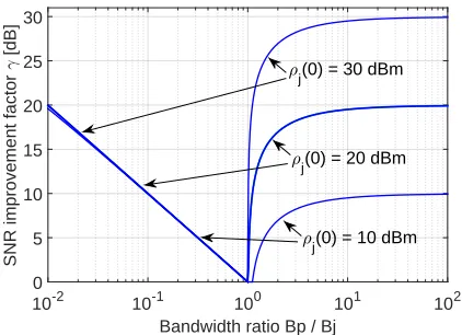
Figure 7: Upper bound on SNR improvement factor for ideal filtering andσn2=0.01.
where Bp andBj correspond to the bandwidths of the bi-nary sequence p(k)and the narrow-band interference j(k) respectively. Note that this expression may become smaller than one when
Bj> ρjρj((00) +) −σ12 nBp.
(10)
This is the case when the bandwidth of the narrow-band jam-mer is close to the bandwidth of the PN sequence. In that case, applying an excision filter is worse than using no fil-ter at all. Therefore, the excision filfil-ter should not be applied prior despreading whenBj> ρρj(0)−1
j(0)+σn2Bp. More precisely, the
upper bound is therefore
γ=⎧⎪⎪⎪⎪⎨ ⎪⎪⎪⎪ ⎩
ρj(0)+σn2 Bp Bp−B j(1+σ2n)
ifBj≤ ρρj(0)−1
j(0)+σ2nBp,
1 ifBj> ρρj(0)−1
j(0)+σ2nBp.
(11)
Upper bound for wide-band jamming:In case of a wide-band jammer, the ideal filter is a low-pass filter that is per-fectly matched to the bandwidth of the PN sequence. The PN sequence does hence not experience any self-noise. As-suming that the interference is white, we can also express the residual interference after filtering as a function of the bandwidth ratio between jammer and PN sequence as
γ= Bρpj(0) +σn2 Bjρj(0) +σn2
,Bj>Bp. (12)
Discussion:An interesting observation is that the improve-ment factor is asymmetric. For illustrative purposes, we plot the bound of the SNR improvement factor versus the band-width ratio Bj/Bp in Figure 7. We use σn2 = 0.01 and the improvement factor is plotted on a logarithmic scale
Bandwidth ratio Bp / Bj
0.5 1 1.5 2
SNR improvement factor
.
[dB]
0 5 10 15 20 25 30
;
j(0) = 30 dBm
;
j(0) = 20 dBm
;
j(0) = 10 dBm
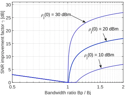
Figure 8: Zoomed version of the upper bound on SNR improvement factor shown in Figure 7.
20dB according to eq. (12). We can see that for this band-width ratio range, the SNR improvement is almost indepen-dent of the jamming power and primarily determined by the bandwidth offset. ForBp/Bj >1and very small bandwidth offsets, the improvement factor remains one because the ex-cision filter is not used as it would degrade the SNR more than without any filtering. For higher bandwidth offsets, the SNR improvement factor quickly converges to a value that is close to the power of the jammer, i.e.,10,20and30dBm in the Figure. Thus, the improvement is highest for strong jam-mers with a large bandwidth offset. Yet, a zoomed version is shown in Figure 8 and it indicates that significant gains can be achieved by BHSS for bandwidth ratios between0.5and
2.
5.3
Bit Error Performance
The results given above on SNR improvement indicate that significant performance gains can be achieved when the bandwidth of the signal and the bandwidth of the jammer have an offset. The analysis below compares the bit error rate of a BHSS signal against conventional DSSS and FHSS systems for jammers with fixed bandwidths as well as ran-domly hopping jammers.
In order to compute the bit error rate, we express the out-put of the demodulator, which is the decision variable for recovering the binary information, as
U=∑L
k=1y(k)p(k)
(14)
and we assume that the decision variableU has a Gaussian distribution. This is equivalent to assuming that the perfor-mance of this system is the same as that of QPSK signaling corrupted only by white Gaussian noise with variance equal to the total noise due to white noise, interference, and self-noise at the output of the demodulator. Under these assump-tions, the bit error rate is given by
Pb=P(U<0) =
∫
0−∞
1
√
2πσe
−(U−µ)2
2σ2 dU (15)
whereσ2 = var(U)and µ = E(U)are derived in the
Ap-E b/No [dB]
0 5 10 15 20
Bit error rate
10-10 10-8 10-6 10-4 10-2 100
DSSS and FHSS
BHSS: B
j/max(Bp) = 1 BHSS: B
j/max(Bp) = 0.3 BHSS: B
j/max(Bp) = 0.1 BHSS: B
j/max(Bp) = 0.03 BHSS: B
j/max(Bp) = 0.01 BHSS: B
j = random
Figure 9: Bit error probability of BHSS compared to DSSS and FHSS. Signal-to-jamming ratio is−20dB, pro-cessing gain isL =20dB and bandwidth hopping range is100.
pendix (eq. (19) and (20)). Thus,
Pb= 21erfc(
√ µ2
2σ2) =
1 2erfc(
√
SNR
2 ), (16)
where the SNR for a bandwidth hopping and a conventional receiver are given in eq. (6) and (7).
In order to compare the performance of a BHSS receiver to the DSSS and FHSS receivers, we plot the bit error rate against the SNR without interference, i.e., the signal-to-white Gaussian noise ratio per bitEb/No, whereEb is the energy per bit andN0the single-sided spectral density of the Gaus-sian noise. Figure 9 illustrates the error rate performance for a BHSS transmitter that hops randomly among a bandwidth range of 100, i.e., max(min(BBp)
p) = 100. For BHSS, DSSS, and
FHSS, the signal-to-interference ratio per chip is left con-stant at−20dB, the noise is σn2 = 0.01and the processing gain isL = 20dB. In the case of DSSS, the jammer band-widthBjis matched to the same bandwidth as the spreaded signal. Since we restrict our communication systems to the same available bandwidth, FHSS achieves the same jamming resistance as DSSS by using narrower sub-channels in the frequency band. For BHSS, the jammer cannot match its bandwidth to the signal since the bandwidth is changed faster than the reaction time of the jammer and we therefore con-sider jamming strategies which employ fixed jamming band-widths between the minimum and maximum bandwidth used by BHSS, as well as a random bandwidth hopping jammer analogous to the BHSS signal.
B
j / max (Bp)
10-2 10-1 100
Bit error rate
10-15 10-10 10-5 100
SJR = -15 dB
SJR = -10 dB SJR = -20 dB
Figure 10: Bit error probability of BHSS versus different jamming bandwidths. Bandwidth hopping range is100 and processing gain isL=20dB.
also hopping its bandwidth randomly, the bit error rate for Eb/No=15dB drops to about10−7which is better than when the jammer fixes its bandwidth to valuesBj/max(Bp) >0.1, but worse than for values below 0.1. This suggests that a jammer may be better off by jamming with a fixed band-width than by hopping its bandband-width randomly. However, a BHSS system may also respond to jammers of fixed band-width by stopping to hop and selecting a bandband-width that achieves the lowest bit error rate given the bandwidth of the jammer. Therefore, a jammer is forced to also employ a ran-dom hopping strategy to counterfeit adaptive BHSS systems. In Figure 10, we further plot the bit error rate of BHSS versus the bandwidth of the jammerBj for different signal-to-jamming ratios (SJR). The processing gain is again L =
20dB and the bandwidth hopping range of BHSS is100. As we can see, the bit error curves for the different SJR values all exhibit a maximum at different jammer bandwidths. A jammer will hence maximize the bit error rate by selecting a jamming bandwidth which is matched to the SJR. However, it may be challenging for the jammer to estimate the exact SJR at the receiver, specially when the transmitter or receiver are mobile. When the jammer is not able to estimate the SJR, he may again be better off by randomly hopping across all bandwidths that are used by BHSS.
5.4
Throughput Comparison
The previous results have shown that BHSS outperforms DSSS and FHSS in terms of bit error rate. However, since BHSS sacrifices transmission rate when hopping to smaller bandwidths, an interesting question is whether the overall throughput of BHSS can still be higher or at least equal to DSSS and FHSS despite the hopping to smaller bandwidths for jamming mitigation.
To answer this question, we compare the throughput of all three systems using a packet-based communication model. IfPp is the packet error probability, the throughput can be expressed as
T=R(1−Pp), (17) whereRcorresponds to the packet transmission data rate in
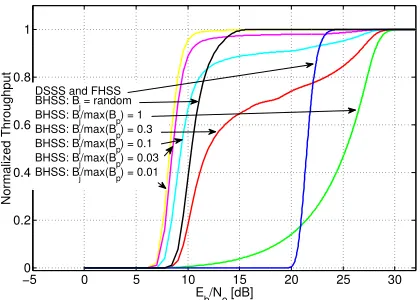
−50 0 5 10 15 20 25 30
0.2 0.4 0.6 0.8 1
Eb/No[dB]
Normalized
Thro
ughput
DSSS and FHSS BHSS: Bj= random BHSS: Bj/max(Bp) = 1 BHSS: Bj/max(Bp) = 0.3 BHSS: Bj/max(Bp) = 0.1 BHSS: Bj/max(Bp) = 0.03 BHSS: Bj/max(Bp) = 0.01
Figure 11: Throughput of BHSS compared to DSSS and FHSS. Signal-to-jamming ratio is−20dB and bandwidth hopping range is100.
bits per second. In absence of channel coding, a packet is declared incorrect if at least one bit is erroneous. Assuming that the bit errors are i.i.d., from digital communication the-ory [20], the expectation value of the packet error probability for a data packet length ofNbits is then
Pp=1− (1−Pb)N. (18)
To compare the throughput in a fair manner, we fix the rateRand the spectral occupancy of each system to identical values. In other words, we compare the throughput of each system for equal capacity with the signal bandwidth of each system computed as previously in Section 5.3. To do so, we use a processing gain and bandwidth hopping range for BHSS ofLBHSS =20dB and max(min(BBp)
p) =100respectively, and
configure the processing gain of DSSS and FHSS to achieve the same data transmission rate R as BHSS. This config-uration results in processing gains for DSSS and FHSS of LDSSS =LFHSS =25.4dB.
curves are separated by roughly12dB, meaning that a DSSS or FHSS system would need to increase its processing gain by that amount in order to achieve the same jamming resis-tance as BHSS. In other words, this means that a DSSS or FHSS system requires sixteen times more radio-frequency bandwidth than a BHSS system to achieve the same through-put under jamming.
6.
EXPERIMENTAL RESULTS
This section presents experimental results we obtained with a prototype BHSS system implemented on software-defined radios (SDR). The goal of these experimental results is to assess the power advantage of BHSS over classical SS un-der more realistic system assumptions than in the theoretical analysis from the previous section which assumed an ideal receiver with ideal filters. With real hardware components, the receiver must deal with frequency, timing, phase, and sampling noise which will impact the receiver performance under jamming. In addition, the excision and low-pass fil-ters may no longer entirely remove the undesired frequen-cies from the jammer without distorting the signal from the transmitter.
6.1
Implementation on SDR
Our implementation relies on the GnuRadio framework for software-defined radios from Ettus Research. We have implemented a BHSS transmitter and receiver for the QPSK modulation. The system relies on a 16-ary DSSS modulation similar to the one used in IEEE 802.15.4 [21]. The DSSS system spreads 4-bit symbols to32chips, corresponding to a spreading factor of8, or a processing gain of9dB. In analogy to IEEE 802.15.4 frames, the frame structure we implement is based on a preamble, start of frame delimiter (SFD), data and a cyclic redundancy check (CRC). The preamble and SFD serve for frame, frequency, time, and phase synchro-nization at the receiver. The CRC is used to check whether frames are correctly received.
We rely for our experiments on the USRP N210 which offers a maximum bandwidth of50MHz. However, because of the limited resources of our system setup, the maximum number of samples we are able to process in real-time on the receiver computer is20MS/s, limiting the bandwidth of our signals to a maximum of10MHz. Our implementation therefore supports a configurable signal bandwidth ofBp =
10
nMHz, with n ≥ 1. All signal bandwidths are sampled at the same, maximum sampling rate Rs of 20MS/s in order to avoid processing delays when the sampling rate would be switched while hopping.
For the modulation of the chips, we rely on a half-sine pulse shapeg(t). The duration of the half-sine pulse shape is changed after a configurable number of symbols. In prin-ciple, it would be possible to change the pulse shape after the transmission of each chip. However, sub-symbol band-width hopping is not necessary as it is safe to assume that the jammer will need at least a couple of symbols to estimate the signal bandwidth in order to react with the matched jamming signal [12]. For the purpose of our experiments, transmitter and receiver have a pre-shared random bandwidth hopping
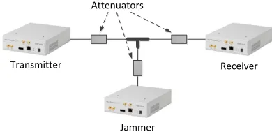
Transmitter
Jammer
Receiver Attenuators
Figure 12: Experimental setup with BHSS transmitter, BHSS receiver and jammer.
sequence.
The receiver estimates the power spectral density of the in-terference using an FFT. Upon estimation of the spectral den-sity, a control logic applies an appropriate FIR filter configu-ration to suppress the jammer prior demodulating the signal. In order to minimize the processing delays, we pre-compute the taps of all possible low-pass filters in advance with the GnuRadio filter design tool. The tabs of the excision fil-ters are set in order to be reciprocal to the square root of the power spectral density of the jammer, as shown in eq. (3). We use the maximum number of taps supported by our re-ceiver hardware resources to process the incoming samples in real-time. This results in a maximum filter order of3181 for a transition width of10kHz and stop-band attenuation of
70dB.
Real receivers need to be able to tolerate frequency, phase and timing errors which occur due to clock, sampling, and channel noise. The mechanisms to correct these offsets are all implemented after the FIR filter. Otherwise, the jammer may disturb the error correction and the gain of the filter may not be fully exploited. Phase and frequency are corrected with the help of a Costas loop [22] while timing synchro-nization is achieved with the Gardner timing recovery [23]. After frequency, time and phase correction, the signal is de-modulated with a filter matched to the half sine pulse shape currently being employed by the transmitter. After chip de-modulation, the receiver then correlates each sequence of32 chips (a symbol) with the16 different symbols and selects the one with the highest correlation.
6.2
Experimental Setup
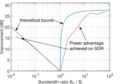
Bandwidth ratio Bp/ Bj
10-2 10-1 100 101 102
Improvement
[dB
]
0 5 10 15 20 25 30
Power advantage achieved on SDR theoretical bound
Figure 13: Power advantage achieved with our SDR-based implementation.
are representative of real-world scenarios in which the radios communicate to each other with antennas over line-of-sight because both channels can be modeled as additive white Gaus-sian noise (AWGN) channels. Another realistic setup of our experiments is that we do not synchronize the clocks of the SDRs and all of them use their own internal oscillator. Dif-ferent power levels for the transmitter and jammer are pro-duced by adding different attenuators at the cable ends and by varying the transmit gain of the SDRs. In all experiments, we hop between a set of seven pre-defined bandwidths: 10,
5, 2.5, 1.25, 0.625, 0.312, and 0.156MHz. The bandwidth hopping range is therefore64. All the results reported in this Section are derived by averaging the performance over
10, 000transmitted packets for all data points.
6.3
Power Advantage for Fixed Bandwidth
Offsets
In order to compare the performance of our SDR-based implementation to the theoretical bound from Section 5.1, we first determine the minimal SNR required to achieve a particular error performance with and without interference filtering for fixed bandwidth offsets between jammer and sig-nal, i.e., when the bandwidth is not hopping. In analogy to the SNR improvement factor in eq. (8), we define thepower advantageas the ratio of the SNRs to achieve an error perfor-mance below50percent packet losses without and with filter. A packet loss is defined as a packet for which the CRC does not match the content of the packet. The power advantage is directly comparable to the SNR improvement factor as both indicate how much stronger the power of the signal must be when no interference is suppressed before the despreading operation.
We have measured the power advantage for49bandwidth offset constellations between the seven pre-defined signal bandwidths and the same seven bandwidths for the jammer. For all constellations having identical bandwidth ratio,Bp/Bj, we average the power advantage and plot the result in Figure 13. As a reference, we also show the theoretical bound for the SNR improvement factorγas derived in the Section 5.1. We observe that for offsetsBp/Bj<1, the achieved power ad-vantage as measured with our implementation follows very
Bandwidth [MHz] 10 5 2.5 1.25 0.625 0.313 0.156 Linear[%] 14.3 14.3 14.3 14.3 14.3 14.3 14.3 Exponential[%] 50.4 25.2 12.6 6.3 3.1 1.6 0.8 Parabolic[%] 27.1 15.8 6.3 0.1 1.3 22.0 27.4
Table 1: Random distributions for the different hopping patterns.
closely the theoretical bound. In this regime, the bandwidth of the jammer is wide-band and the low-pass filter is active. It shows that the low-pass filter as implemented using the FIR filter is quite optimal at suppressing the frequencies of the jammer without distortion of the original signal. In con-trast, forBp/Bj>1, our implementation is not able to the ex-ploit the full theoretical gain. Specially, for10>Bp/Bj >1, the implementation sacrifices roughly half of the possibly achievable SNR improvement. This is the result from fac-tors such as the non-ideal excision filters, or the fact that the jammer and the chip sequences are not entirely white given the limited processing gain of9dB we have with a spreading factor of8. Yet, forBp/Bj>10, we observe significant gains of more than25dB as expected.
6.4
Power Advantage with Bandwidth
Hop-ping
Next, we analyze the power advantage of BHSS versus the spread spectrum receiver with fixed bandwidth. To have comparable results, we use for the latter the same code base as BHSS but disable bandwidth hopping. First, we introduce the three different hopping patterns we have implemented for our tests. Then, we evaluate the performance of these hop-ping patterns for jammers of fixed bandwidth and for jam-mers that hop according to the same patterns.
6.4.1
Hopping Patterns
We have implemented the following three hopping pat-terns:
Linear hopping: With this pattern, the transmitter hops according to a uniform random distribution within the set of possible bandwidths. In our experiments with 7 band-widths from 0.15625 to 10MHz, this results in an average bandwidth utilization of2.83MHz and an average through-put of354kb/s.
Exponential hopping: The exponential hopping pattern is chosen such that on average each bandwidth is used for the same amount of time. It compensates for the unequal trans-mit time of the different bandwidths by drawing randomly from the set of available bandwidths according to an expo-nential distribution. This results in an average bandwidth of
6.72MHz and a throughput of840kb/s.
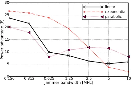
advan-0.156 0.312 0.625 1.25 2.5 5 10 Jammer bandwidth [MHz]
0 5 10 15 20 25 30
Power
adv
antage
(P)
linear exponential parabolic
Figure 14: Power advantage versus jamming bandwidth for linear, exponential and parabolic hopping patterns.
tage over all possible bandwidths is the best option against an attacker which matches its bandwidth to the one with low-est power advantage. It results in an average bandwidth of
3.77MHz and an average throughput of471kb/s. The exact distributions of all three strategies are given in Table 1.
6.4.2
Fixed Jammer Bandwidth
Figure 14 shows the power advantage of BHSS for the different hopping patterns and jammers of fixed bandwidths. The power advantage is defined for this plot as the ratio of the minimum SNRs to achieve an error performance below
50percent packet losses for BHSS and the fixed-bandwidth receiver. For the fixed-bandwidth receiver, we use the max-imum bandwidth of BHSS, i.e.,10MHz for the signal and the jammer. The power advantage therefore corresponds to the SNR improvement of BHSS over conventional DSSS for equal RF spectrum requirements. As we can see, BHSS is able to achieve considerable improvements. Depending on the hopping pattern and jamming bandwidth, power advan-tages between2dB and26dB are achieved. The empirical results further confirm that the power advantage consider-ably depends on the bandwidth of the jammer. Interestingly, the jamming bandwidth that minimizes the power advantage of BHSS is different for the different hopping patterns. The minimum power advantage for the linear hopping pattern is at5MHz jamming bandwidth, while it is at0.625MHz for the parabolic and at10MHz for the exponential hopping pat-terns. In contrast, the highest power advantage is achieved for a jamming bandwidth of0.156MHz for all hopping pat-terns. This can be explained by the bandwidth hopping range of 64 we are using in our experiments. For this limited range, the power advantage for large bandwidth ratiosBp/Bj is larger than for small bandwidth ratios because of the asym-metry of the SNR improvement factor for low-pass and ex-cision filtering (see Figure 13). Narrow-band jammers are therefore on average filtered more effectively than wide-band jammers. By using larger bandwidth hopping ranges, the highest power advantage might be therefore at different jam-ming bandwidths for different hopping patterns.
Considering this result, a jammer might be tempted to jam using a fixed bandwidth that achieves the lowest power ad-vantage. However, as mentioned earlier, relying on a fixed
Hopping pattern jammer
linear exponential parabolic
Hopping patter
n
signal
linear 9.6 6.5 12.5
exponential 15.7 3.3 15.2
parabolic 12.2 11.4 13.7
Table 2: Power advantage in dB for different bandwidth hopping patterns for BHSS and the jammer.
jamming bandwidth as a jammer might be not be the best strategy as after detection that the jammer is using a fixed bandwidth, the transmitter could also switch to a fixed band-width having the largest offset to the jammer and therefore maximizing the power advantage for the receiver. In order to avoid this situation, the jammer should also hop its band-width randomly. The performance against bandband-width hop-ping jammers is the focus of the following sub-section.
6.4.3
Bandwidth Hopping Jammer
In a next step, we analyze the power advantage for ran-dom hopping jammers. We consider the same hopping pat-terns for the jammer as for BHSS. Table 2 summarizes the power advantage for all nine combinations of hopping pat-terns between signal and jammer. As we observe, the hop-ping pattern greatly affects the power advantage. The high-est power advantage of15.7dB is achieved when the signal is hopping according to the exponential pattern and the jammer follows the linear hopping pattern. However, the exponential hopping pattern is worst (3.3dB) when the jammer is also hopping its bandwidth according to the exponential hopping pattern. From this perspective, BHSS should not rely on this pattern as it is not the most robust one against any of the three types of jammer. The most robust pattern is the parabolic pattern. If the signal follows this pattern, the worst power advantage is11.4dB, when the jammer is hopping according to the exponential pattern.
7.
RELATED WORK
bandwidth over a wider band than actually occupied by the information bandwidth. The jammer interference can then be suppressed at the receiver by bandpass filtering the received signal according to the instantaneous carrier frequency used by the transmitter. Similar to DSSS, the demodulation op-eration of FHSS has the effect of mitigating the amount of interference power to a fraction that is proportional to the ra-tio between the hopping band to the actual signal bandwidth. In theory, any level of jamming suppression can be achieved with DSSS or FHSS by using a sufficient processing gain [8, 9]. However, high processing gains require large spreading of the signal bandwidths. Since the RF spectrum is a scarce resource today, achieving jamming resistance using arbitrary large bandwidths is generally not always possible.
Excision filters have been proposed in conjunction to the spread spectrum receivers in order to augment the process-ing gain without an increase in signal bandwidth [4, 5, 6, 7]. However, excision filters alone are not effective at suppress-ing interference from jammers since the interference can be matched by the jammer to the bandwidth of the signal which makes excision filtering ineffective. In this work, we also rely on excision filters to suppress narrow-band jammers, however by making use of bandwidth hopping, we are able to improve the processing gain in the presence of intentional interference from jamming.
DeBruhl and Tague [25] proposed using adaptive filters to mitigate the impact of jamming in spread spectrum sys-tems. Their approach targeted however only periodic jam-mers which are not able to quickly match desired waveforms while sensing the channel. In contrast, BHSS provides im-provements against also reactive jammers.
Wireless communication systems have generally been de-signed to operate at fixed bandwidths. Some more recent sys-tems support adaptive signal bandwidths, but the bandwidths are not switched in the same way. For example in [10], the authors propose SampleWidth, an algorithm that sam-ples the channel conditions and dynamically switches be-tween different bandwidths. Pejovic and Belding proposed WhiteRate in [11], a context-aware approach to wireless rate adaptation. While also adapting the signal width, the goal of SampleWidth and WhiteRate is entirely different from BHSS. These works try to improve the throughput in an non-adversarial setting while BHSS aims at mitigating the impact of adversarial interference. Therefore, our design relies on fast and unpredictable bandwidth hopping patterns provid-ing the protection against an attacker that tries to disturb the communication.
Extensions of DSSS and FHSS have been proposed such as UDSSS [17] and UFH [26]. However, the basic spread-ing principles of these extensions remain the same, whereas BHSS spreads the signal by hopping it across different band-widths, a hopping dimension that has been not exploited so far by any other spread spectrum techniques.
Several anti-jamming techniques have been proposed which do not rely on spread spectrum methods. For example, di-rectional antennas [13] offer a higher degree of protection by restricting the direction from which an attacker may emit in-terference, at the cost of restricting also the direction of the
communication. Multiple antenna systems and beamforming can also be used to alleviate this problem [14]. By spacing the multiple antennas at least half of the wavelength from each other, the jammer signal can be isolated from the reg-ular communication and subtracted at the receiver. Unlike multiple antenna systems, BHSS is able to mitigate the im-pact of adversarial interference using a single antenna.
8.
CONCLUSION
Spread spectrum communication inherently provides in-terference resistance against jamming, however the process-ing gain is bounded by the spreadprocess-ing factor. Conventional spread spectrum systems therefore require to increase the frequency band occupation of the signal in order to achieve a desirable jamming resistence. In this work, we have pro-posed bandwidth hopping as a technique to increase the jam-ming resistence of spread spectrum communications without the need to increase the occupied frequency band of the sig-nal. We have derived a theoretical bound for the SNR and bit error rate improvement of BHSS over conventional DSSS and FHSS. We have designed and implemented transmitter and receiver structures on software-defined radios to hop the bandwidth during the transmission of the signal which al-low us to hop the bandwidth fast enough to protect against reactive jamming. Our experimental results on software-defined radios confirm that significant improvements can be achieved on real systems. In our experiments, we were able to achieve power advantages from8to20dB against fixed-bandwidth jammers for a fixed-bandwidth hopping range of64. When both the signal and the jammers are hopping randomly their bandwidths, we achieved an average power advantage of11.4dB for BHSS. These results demonstrate that the pro-cessing gain of spread spectrum systems can be improved beyond the spreading factor, even against a strong attacker model such as reactive jamming.
Acknowledgments
We thank our shepherd Shyamnath Gollakota for the con-structive feedbacks. This work has been funded in part by the European Commission in the framework of the H2020-ICT-2014-2 project Flex5Gware (Grant agreement no. 671563) and in part by Ministerio de Economía y Competitividad grant TEC2014-55713-R.
9.
REFERENCES
[1] R. A. Poisel,Modern communications jamming principles and techniques. Artech House Publishers, 2004. [2] D. L. Adamy,EW 102: A Second Course in Electronic
Warfare. Artech House, 2004.
[3] F. M. Hsu and A. A. Giordano, “Digital Whitening
Techniques for Improving Spread Spectrum Communications Performance in the Presence of Narrow-band Jamming and Interference,”IEEE Transactions on Communications, vol. 26, February 1978.
[5] M. G. Amin, C. Wang, and A. R. Lindsey, “Optimum Interference Excision in Spread Spectrum Communications Using Open-Loop Adaptive Filters,”IEEE Transactions on Signal Processing, vol. 47, no. 7, July 1999.
[6] L. B. Milstein and R. A. Iltis, “Signal Processing for Interference Rejection in Spread Spectrum
Communications,”IEEE ASSP Magazine, April 1986. [7] J. W. Ketchum and J. G. Proakis, “Adaptive Algorithms for
Estimating and Supressing Narrow-Band Interference in PN Spread Spectrum Systems,”IEEE Transactions on
Communications, vol. 30, no. 5, May 1982.
[8] A. Goldsmith,Wireless Communications. Cambridge University Press, 2004.
[9] J. Proakis,Digital Communications, 3rd ed. McGraw Hill, 2001.
[10] R. Chandra, R. Mahajan, T. Moscibroda, R. Raghavendra, and P. Bahl, “A case for adapting channel width in wireless networks,” inACM SIGCOMM ’08, 2008, pp. 135–146. [11] V. Pejovic and E. M. Belding, “Whiterate: A context-aware
approach to wireless rate adaptation,”IEEE Transactions on Mobile Computing, vol. 13, no. 4, April 2014.
[12] M. Wilhelm, I. Martinovic, J. B. Schmitt, and V. Lenders, “Short paper: Reactive jamming in wireless networks: How realistic is the threat?” inProceedings ACM Conference on Wireless Network Security (WiSec), 2011, pp. 47–52. [13] A. Mpitziopoulos, D. Gavalas, C. Konstantopoulos, and G. E.
Pantziou, “A survey on jamming attacks and
countermeasures in wsns,”IEEE Communications Surveys and Tutorials, vol. 11, no. 4, pp. 42–56, 2009.
[14] T. D. Vo-Huu, E.-O. Blass, and G. Noubir, “Counter-jamming using mixed mechanical and software interference
cancellation,” inProceedings of the Sixth ACM Conference on Security and Privacy in Wireless and Mobile Networks, ser. WiSec ’13, New York, NY, USA, 2013, pp. 31–42. [15] D. Bharadia, E. McMilin, and S. Katti, “Full duplex radios,”
inACM SIGCOMM, August 2013.
[16] M. K. Simon, K. K. Omura, R. A. Scholtz, and B. K. Levitt,
Spread Spectrum Communications Handbook. McGraw-Hill, 2002.
[17] C. Pöpper, M. Strasser, and S. Capkun, “Anti-jamming broadcast communication using uncoordinated spread spectrum techniques,”IEEE Journal on Selected Areas in Communications, vol. 28, no. 5, pp. 703–715, 2010. [18] M. S. Batlett, “Smoothing Periodograms from Time-Series
with Continuous Spectra,”Nature, vol. 161, May 1948. [19] P. D. Welch, “The use of fast Fourier transform for the
estimation of power spectra: A method based on time averaging over short, modified periodograms,”IEEE Transactions on Audio and Electroacoustics, vol. 15, no. 2, June 1967.
[20] J. Proakis and M. Salehi,Digital Communications, ser. McGraw-Hill higher education. McGraw-Hill Education, 2007. [Online]. Available:
http://books.google.ch/books?id=HroiQAAACAAJ [21] “IEEE Standard for Local and metropolitan area
networks–Part 15.4: Low-Rate Wireless Personal Area Networks (LR-WPANs),”IEEE Std 802.15.4-2011 (Revision of IEEE Std 802.15.4-2006), pp. 1–314, Sept 2011.
[22] K. Mueller and M. Muller, “Timing recovery in digital synchronous data receivers,”Communications, IEEE Transactions on, vol. 24, no. 5, pp. 516–531, May 1976. [23] F. M. Gardner, “A bpsk/qpsk timing-error detector for
sampled receivers,”Communications, IEEE Transactions on, vol. 34, no. 5, pp. 423–429, May 1986.
[24] R. L. Pickholtz, D. L. Schilling, Laurence, B. Milstein, and S. Member, “Theory of spread spectrum communications: a tutorial,”IEEE Transactions on Communications, vol. 30, pp. 855–884, 1982.
[25] B. DeBruhl and P. Tague, “Mitigation of Periodic Jamming in a Spread Spectrum System by Adaptive Filter Selection,” in
International Conference on Pervasive and Embedded Computing and Communication Systems (PECCS), February 2012.
[26] M. Strasser, C. Pöpper, and S. ˇCapkun, “Efficient uncoordinated fhss anti-jamming communication,” in
Proceedings of the Tenth ACM International Symposium on Mobile Ad Hoc Networking and Computing, ser. MobiHoc ’09, 2009, pp. 207–218.
Appendix
In order to demonstrate the effectiveness of the narrow-band and wide-band interference suppression techniques, we shall compare the performance of the receiver with and without the suppression filters for different jamming-signal bandwidth offsets. The received signalr(k)is first fed as input to the filter and the output is
y(k) =
K−1
∑
l=0
h(l)r(k−l),k=1, 2, ...
=
K−1
∑
l=0
h(l)[p(k−l) +j(k−l) +n(k−l)].
The signal is then fed to the PN correlator. The output of the PN correlator, which is the decision variable for recovering the binary information, is expressed as
U=
L
∑
k=1
y(k)p(k)
whereLrepresents the number of chips per information bit (also re-ferred to as symbol) or the processing gain. To determine the SNR, we must compute the mean and variance ofU[7]. We assume that the PN sequencep(k)is white, the interferencej(k)has zero mean
and autocorrelation functionρj(k), and the additive noisen(k)is
white with varianceσn2. Then, the mean ofUis
E(U) =L (19)
and the variance is
var(U) =L
K−1
∑
l=1
h2
(l) +L
K−1
∑
l=0
K−1
∑
m=0
h(l)h(m)ρj(l−m)
+Lσn2
K−1
∑
l=0
h2
(l). (20)
The first term on the right-hand side of the expression for the vari-ance represents the mean square value of the self-noise due to the time dispersion introduced by the interference suppression filter. The second term is the mean square value of the residual interfer-ence. The last term is the mean square value of the wide-band noise. The SNR at the output of the correlator is defined as the ratio of the square of the mean to the variance [7], and it is then computed as:
SNR= L
K−1
∑
l=1
h2(l) +
K−1
∑
l=0
K−1
∑
m=0
h(l)h(m)ρj(l−m) +σn2
K−1
∑
l=0
h2(l)