A Note on the 3D Structural Design of Electrospun
Nanofibers
Maryam Yousefzadeh1, Masoud Latifi1, Mohammad Amani-Tehran1, Wee-Eong Teo2, Seeram Ramakrishna2
1
Amirkabir University of Technology, Tehran IRAN
2
National University of Singapore SINGAPORE
Correspondence to:
Maryam Yousefzadeh email: [email protected]
ABSTRACT
In this paper, various three-dimensional (3D) nanofibrous structures were constructed based on liquid support systems and alteration of the solution charge property. Structures fabricated from the liquid support system include a nanofibrous ring and spindle-shaped nanofibrous ones. The ease of fabricating fluffy, randomly organized nanofibrous structure by altering the charge capacity of the electrospun solution is also demonstrated. The set-up conditions for the design of the nanofibrous structures using these techniques are discussed.
INTRODUCTION
Over the last decade, electrospinning has become a widely adopted technology for fabricating nanofibers. However, since it was first patented in 1902, [1, 2] most researchers adopt the same basic set-up as described in the early patents. As a result, the vast majority of the nanofibrous structures produced are still in the form of flat nanofibrous membranes, although there are some reports on in situ fabrication of aligned nanofibrous membrane, [3-6] nanofibrous yarns [7-10] and 3D nanofibrous structures. [11] To appreciate the difficulty of fabricating nanofibrous structure beyond flat membranes, understanding the electrospinning process seems to be of great importance.
In electrospinning, the formation of fiber is accomplished by using a strong electric field to continuously draw a polymer fluid to a collector. Therefore, a typical electrospinning set-up would consist of a high voltage power supply, a nozzle, a reservoir for polymer solutions, and a collector. When a polymer solution is charged to a critical voltage, the repulsive force exerted by the presence of like-charges within the solution will surpass the surface tension of the droplet and a solution jet erupts and accelerates towards an electrically earthed or oppositely charged collector. The combination of various forces on the jet such as viscoelastic force
and electrical repulsion create a chaotic flight path towards the collector. [12, 13] The deposited nanofibers subsequently discharged allow the incoming fibers to lie on the top of the preceding fibers and form a random nanofibrous membrane.
The web nanofibrous structure makes it ideal for filtration applications and has been adopted by filtration companies such as Donaldson in their commercial products. The high surface area to volume ratio of the nanofibrous membrane has prompted further investigation into other applications such as energy, water filtration, sensors and tissue engineering. [14, 15] However, limitations in the variety of nanofibrous structures that can be constructed would restrict the performance of the device.
One of the most investigated applications of the electrospun structure is in tissue engineering. Many different cells have been successfully cultured on electrospun membranes. [16] However, many natural extracellular matrices are made of 3D networks of nanometer sized fibers [17] such as bone, cartilage, and soft tissue fillers to name only a few. Several in vivo studies have shown that nanofibrous membranes are able to facilitate bone healing despite the flat membrane form. [18,19] Thus, a 3D nanofibrous scaffold would present a more natural form for application. The soft feel (very low stiffness) of the 3D nanofibrous scaffold also makes it ideal for use as cosmetic fillers and filling volume defects. Current fillers are generally in the form of micro-particles or gels which do not mimic the nanofibrous nature of ECMs. It is, therefore, desirable to construct a similar 3D nanofibrous network for tissue engineering or tissue regeneration applications.
surface tension solvent such as methanol. As the fiber lands on the solvent surface, it sinks while further fibers get deposited. Over time, a relatively thick layer of fibers would accumulate. [20] This 3D nanofiber was shown to support cell proliferation inside the fiber matrices. Another method to fabricate 3D nanofibrous structure is to use a collector that is cooled to below water freezing temperature. This causes ice-crystals to form on the collector and over the deposited nanofibers as more nanofibers accumulate. [21]
But still most techniques of fabricating 3D nanofibrous structures are largely based on fiber accumulation and build up on a flat surface. Therefore, building thick structures are likely to take some time. Moreover, the macrostructure that can be constructed is also limited. In this paper, techniques to construct different 3D nanofibrous structures are presented. The influence of how charges on the electrospinning jet allow for in situ formation of 3D nanofibrous structures is also illustrated. Multi-walled carbon nanotube (MWNT) is used as the model additives to increase the charges on the electrospinning jet. [22, 23]
EXPERIMENTAL SET-UP
Industrial-grade Polyacrylonitrile (PAN) from Iran Polyacryle Co. (Mw 100,000 g/mol) and N, N-dimethyl formamide (DMF) were used as a solvent to prepare a solution with a concentration of 14-16% (w/v). Multi-walled carbon nanotubes (MWNT) with purity of more than 95%, and lengths between 5-15 µm and 10-20 nm in diameters were also used in this experiment.
MWNT’s with the concentration of 0.5-1% (wt.) were dispersed in a DMF using a probe sonicatore (SONICS) at room temperature for about 1 hour. A magnet stirrer (VISION, Scientific Co., LTD.) was used to mix the polymer with the carbon nanotubes solution until the polymer was uniformly dissolved in the solvent. [24] The microstructure and morphology of the nanofibers were probed using a scanning electron microscope (SEM), Quanta FEG 200.
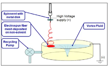
Figure 1 illustrates the general experimental set-up used to fabricate a 3D bulk as well as aligned nanofibrous structures. A positive charged electrode disk with a diameter of 4 cm was used around the nozzle to control and limit the electrical field so that
the nanofibers were deposited under the nozzle. The vortex was formed on the basin with a hole at the bottom allowing water to be drained out into the tank below. A centrifuge pump was employed to circulate the water between the tank and the basin so that the water in the basin maintained at a constant level. The grounded wire was inserted into the basin to remove any residual charge on the water surface.
FIGURE 1. The schematic set-up for the production of 3D nanofibrous structures (bulk and aligned) using liquid vortex.
A voltage of 14-18 kV was applied to the spinneret. The distance between the spinneret tip and the water surface was 12 cm. The spinneret was a B-D 22.5G needle with a flat tip. A KD Scientific syringe pump was used to provide the solution at a constant feed rate of 0.5-1 ml/hr during electrospinning.
In the first set-up, the centrifuge pump was reduced to a minimum so that a low vortex velocity was created. Nanofibers were deposited on the water surface at one side of the basin as shown in Table I.
In the second experimental set-up, the volume flow rate was increased; hence, increasing the linear speed of the vortex. A winding rotating drum and a special guide above the liquid vortex were used to draft nanofibrous yarn. [10]
TABLE I. Schematic of some 3D bulk nanofibrous producing set-ups and their related structures.
Schematic of set-up
Schematic of nanofibrous
structure
1
Ring shape
2
Twisted yarn10
3
Spindle shape
4
Fluffy web
In the final set-up, for electrospinning of the PAN/MWNTs solution, an auxiliary positive electrode disk 4 cm in diameter was used to modify the electrical field so that the spinning zone was restricted between the needle and the collector. An aluminum grounded plate was used as the collector instead.
RESULTS AND DISCUSSION
The principle of nanofiber deposition in an electrospinning set-up with a flat solid collector is the same as the liquid one. Thus, parameters affecting the formation and morphology of the fibers deposited on a solid substrate appear to be similarly applied to a liquid substrate. The advantage of using liquid substrates is thought to be that the fibrous architecture of deposited fibers can be easily
rearranged to other structures by employing water drag force to accumulate nanofibers without any breakage. Depending upon the selected polymer and solution, any type of liquid non-solvent can be used to create the vortex. Thus, in this study, water is used as the non-solvent.
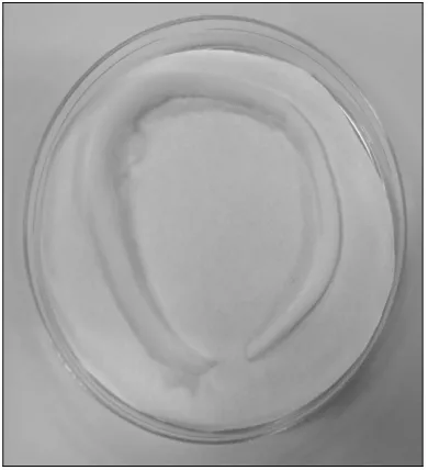
In the first set-up as illustrated in Table I, water circulates around the vortex as the nanofibers deposited on the water surface. In time, continues ring shape of nanofibers is formed as shown in
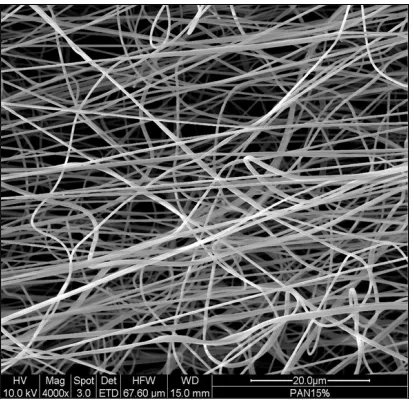
Figure 2. The ring has a thickness of about 15 mm. The SEM image in Figure 3 shows partial orientation of nanofibers along the ring length. PAN nanofibers are relatively hydrophobic and as a result, the fibers float on the water surface. Due to the presence of the electrical charges on the fiber and the inability of the fiber to discharge quickly, slight repulsion between the fibers, as deposited, cause them to be spaced out giving a fluffy ring structure. The circular motion of the water surface causes the nanofibers to be aligned in a circular formation similar to the use of mechanical rotating device to collect the fiber in an oriented fashion. This demonstrates the ability of using water motion to manipulate the nanofibers. An advantage of using water as a collecting substrate is that the nanofibrous structure can be lifted off the water surface with minimal disruption of the nanofibers. In a conventional solid substrate, strong adhesion between the nanofiber and the surface of the collecting substrate tears the nanofiber at the structure-substrate interface. When the nanofibrous ring structure is immersed in water, the surface tension of water results in a compacting of the nanofibrous structure.
FIGURE 3. The SEM image of the ring shape nanofibrous structure.
In a modification of the previous set-up, a grounded bar was placed between the nozzle and the center of the vortex with about 4 cm distance from the surface of the water. A 3D nanofiber spindle shaped structure is formed as illustrated in Figure 4. During electrospinning, the nanofibers are deposited between the tip of the bar and the surface of the vortex. Under the influence of the rotating water vortex, the deposited fibers are swung round the same direction as the rotating vortex below. While one end of the fibers is deposited on the end of the rod, the other end of the fibers deposited on the water is carried to the edge of the vortex where the spinning velocity of the water is at its highest rate. Since one end of the fibers is adhered to the rod, the fibers are prevented from falling down the water vortex. With the swirling motion of the vortex acting on the fiber at one end, while the other is stationary, there is a centrifugal force, as shown in Figure 5, causing the fibers at mid-length to be thrown outwards when deposited. This demonstrates the advantage of using the motion of a fluid to control and move the nanofibers.
FIGURE 4. The spindle shaped nanofibrous structure.
FIGURE 5. Schematic of the centrifugal force acting on the nanofibers.
To demonstrate the effect of increasing the conductivity of the electrospun jet on the deposition characteristics of the nanofibers, MWNTs are added to the PAN solution. When the first layers of the charged nanofibers contact the grounded collector surface, they are rapidly discharged. However, the discharge rate in subsequent layers is expected to be slower because of the poor-conducting polymer nanofibers. After several layers of nanofibers are built up, the accumulated interlayer electrostatic repulsion reduces the packing density of the mat. In this electrospinning set-up, an auxiliary positive electrode disk of 4 cm in diameter is used. Since the nanofibers are collected in a limited area, the PAN/MWNTs nanofibers are forced to accumulate vertically. Rapid vertical accumulation of the nanofibers results in a fluffy web with low packing density as shown in
Figure 6.
FIGURE 6. The 3D fluffy structure of nanofibers deposited on solid substrate with low packing density; (a) during electrospinning, (b) after electrospinning.
nanofibrous web is due to repulsion between nanofibers, as a result of the charges on them, the nature of the substrate has little implication on the fluffiness of the web. Using a deionizer to remove the charges leads to the formation of a more compact web, according to Figure 7. Both nanofibrous webs (with and without the use of deionizer) are deposited on a solid substrate.
FIGURE 7. Compacted thick bulk structure of nanofibers deposited on solid substrate with high packing density.
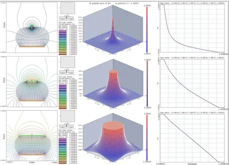
In the set-ups to produce different structures of 3D nanofibers, controlling the depositing area of nanofibers is very important. It is observed in the present study that just having extra disk electrode is sufficient to narrow the deposition area. As it is illustrated in Figure 8, by using the extra positive disk electrode with the needle emerging from the middle, the bending of the electrical field lines between the disk and the collector is minimized. With a larger disk electrode, the electric field lines between the disk and the collector are parallel in the electrospinning zone. This reduces the probability of the electrospinning jet from straying onto a narrow and vertical flight path and through using a smaller disk electrode, the deposition are may appear to be larger.
CONCLUSIONS
Various techniques to construct three-dimensional (3D) structures of nanofibers are introduced in this paper. The liquid collector system, electrical field manipulation, and the electrical discharging on the deposited nanofibers are three key factors used to produce these structures. These nanofiber architectures can be used in tissue scaffolds, filtrations, as well as many other various applications by customizing the nanofibrous mat thickness, packing density, and alignment.
REFERENCES
[1] Cooley, J. F., "Apparatus for electrically dispersing fluids", US Patent, No. 692631, 1902.
[2] Morton, W. J., "Method of Dispersing Fluids",
US Patent, No. 705691, 1902.
[3] Teo, W.E. and Ramakrishna, S., "Electrospun Fiber Bundle Made of Aligned Nanofibers over Two Fixed Points", Nanotechnology, 16, 9, 2005, 1878-1884.
[4] Teo, W. E. and Ramakrishna, S., "A Review on Electrospinning Design and Nanofibre Assemblies", Nanotechnology, 17, 14, 2006, R89-R106.
[5] Kim, G. H. and Kim, W. D., "Formation of
Oriented Nanofibers Using Electrospinning", Appl. Phys. Lett., 88, 2006, 233101.
[6] Wu, Y., Carnell, L. A. and Clark, R. L., "Control of Electrospun Mat width Through the Use of Parallel Auxiliary Electrodes",
Polymer, 48, 19, 2007, 5653-5661.
[7] Pan, H. and et al., "Continuous Aligned Polymer Fibers Produced by a Modified Electrospinning Method", Polymer, 47, 14, 2006, 4901-4904.
[8] Teo, W. E. and et al., "A Dynamic Liquid Support System for Continuous Electrospun Yarn Fabrication", Polymer, 48, 12, 2007, 3400-3405.
[9] Wang, X. and et al., "Continuous Polymer Nanofiber Yarns Prepared by Self-Bundling Electrospinning Method", Polymer, 49, 11, 2008, 2755–2761.
[10] Yousefzadeh, M., et al, "Producing Continuous Twisted Yarn from Well-Aligned Nanofibers by Water Vortex",
Polym. Eng. Sci., 51, 2, 2011, 323-329. [11] Liu, C. K. and et al., "Preparation of Short
Submicron-Fiber Yarn by an Annular Collector through Electrospinning", Mater. Lett., 62, 29, 2008, 4467-4469.
[12] Reneker, D. H. and et al., "Bending Instability of Electrically Charged Liquid Jets of Polymer Solutions in Electrospinning", J. Appl. Phys., 87, 9, 2000, 4531-4547.
[13] Yarin, A. L., Koombhongse, S., Reneker, D. H., "Bending Instability in Electrospinning of Nanofibers", J. Appl. Phys., 89, 5, 2001, 3018-3026.
[14] Ramakrishna, S. and et al., "An Introduction to Electrospinning and Nanofibers", World Scientific, 2005.
[15] Jian, F. and et al., "Applications of Electrospun Nanofibers", Chinese Science Bulletin, 53, 15, 2008, 2265-2286.
[16] Nisbet, D. R. and et al., "A Review of the Cellular Response on Electrospun Nanofibers for Tissue Engineering", J. Biomater. Appl., 24, 1, 2009, 7-29.
[17] Kadler, K. E. and et al., "Collagen Fibril Formation", Biochem. J., 316, 1, 1996, 1-11. [18] Yang, X. and et al., "The Performance of
Dental Pulp Stem Cells on Nanofibrous PCL/gelatin/nHA Scaffolds", J. Biomed. Mater. Res. A, 93, 1, 2010, 247-257.
[19] Seol, Y. J. and et al., "Bioactivity, Pre-Osteoblastic Cell Responses, and Osteoconductivity Evaluations of the Electrospun Non-Woven SiO2-CaO Gel Fabrics", J. Biomed. Mater. Res. B Appl. Biomater., 90, 2, 2009, 679-687.
[20] Ki, C. S. and et al., "Electrospun Three-Dimensional Silk Fibroin Nanofibrous Scaffold", J. Appl. Polym. Sci., 106, 6, 2007, 3922-3928.
[21] Schneider, O. D. and et al., "In Vivo and in Vitro Evaluation of Flexible, Cottonwool-Like Nanocomposites as Bone Substitute Material for complex Defects", Acta. Biomater, 5, 2009, 1775-1784.
[22] Ju, Y. W., Choi, G. R., Jung, H. R., and Lee, W. J., "Electrochemical Properties of Electrospun PAN/MWCNT Carbon Nanofibers Electrodes Coated with Polypyrrole", Electrochimica Acta, 53, 2008, 5796–5803.
[23] Ra, E. J., An, K. H., Kim, K. K., Jeong, S. Y. and Lee, Y. H., "Anisotropic electrical conductivity of MWCNT/PAN Nanofiber Paper", Chemical Physics Letters, 413, 2005, 188–193.
AUTHORS’S ADDRESS Maryam Yousefzadeh Masoud Latifi
Mohammad Amani-Tehran Textile Engineering Department Amirkabir University of Technology Hafez Avenue
Tehran 159163-4311 IRAN
Wee-Eong Teo Seeram Ramakrishna
Nanoscience and Nanotechnology Initiative (NUSNNI)
National University of Singapore 21 Lower Kent Ridge Road, Singapore 119077