Low-Cost 3D Vision Based System for Post-Stroke Arm
Rehabilitation using RGB-D Camera
ABDULLAAL-KAFF1
UC3M - Universidad Carlos III de Madrid LSI - Laboratorio de Sistemas Inteligentes
DISA - Departmento de Ingeniería de Sistemas y Automatica Avenida de la universidad 30, Leganés (28911), Madrid, Spain
1akaff@ing.uc3m.es
Abstract. In this paper, a low-cost markerless system based on RGB-D sensor was developed for re-habilitation purposes. The purpose of this system is to provide the physical therapist with the adequate data to characterize the arm motion in post-stroke rehabilitation, athletic injuries recovery or other pos-sible human arm motion recording and analysis issues. The proposed system uses the Microsoft Kinect sensor to determine the motion of the patient arm. The 3D position of the joints(shoulder, elbowand
wrist)and the centers of mass of arm segments(upperandf orearm)are estimated during the motion. The system then calculates the velocities and energies expenditure by each segment of the arm. More data are estimated by the system such as the angles of each joint(shoulderandelbow)and the angular velocities of the arm segments, where these data are useful to help the therapist with a full overview in the analysis about the patient motion. With the help of these data, the therapist has the analysis of the arm, and comparing with the previous analysis of the patient arm motion, a relative performance can be estimated, allowing a quantitative evaluation of the recovery of the patient over series of exercises. Fur-thermore, as a part of the work, 3D Virtual Reality System(V RS)was developed. This 3D VRS can be a beneficial environment for learning a motor task and it is important in terms of the motion motivation, since it presented to the patient as a rewarded computer game.
Keywords:Markerless Motion Capture, Kinect Sensor, Virtual Reality, Arm Rehabilitation.
(Received July 19th, 2015 / Accepted September 3rd, 2015)
1 Introduction
Stroke is one of the most important causes of disable-ment among elderly people, where more than 17.3 mil-lion people suffer stroke worldwide. Stroke effects usu-ally cause paralysis or in sometimes weakness of one side of the body, which in most cases, this paralysis affects the arm or leg of the patient. Evidences show that additional early exercise maybe beneficial. Reha-bilitation is the term that describes the process of the treatment or recovery from a physical injury or a dis-ease. This process aims to enable the patients to reach and maintain their optimal physical, psychological, in-tellectual, sensory and social functional levels.
Rehabilitation involves a variety of medical cases such as athletic and other sports-related injuries, post-accident rehabilitation. In Addition, it provides dis-abled people with the tools they need to attain indepen-dence and self-determination.
Physical therapy helps to regain the skills and func-tionalities of the human extremities that are lost due to athletic injuries, stroke attack or any pathological cause.
Al-Kaff Low-Cost 3D Vision Based System for Post-Stroke Arm Rehabilitation using RGB-D Camera 2
three main categories based onto the technologies used in each:
• Mechanical-based systems.
• Inertial Measurement-based systems.
• Vision-based systems.
Nevertheless, fusion among them often takes place for achieving better system performance.
In this paper, low-cost vision-based system using the Microsoft Kinect sensor is presented to facilitate post-stroke rehabilitation monitoring and assessment as shown in Figure 1. This system is able to obtain the positions, angles, and velocities of the arm joints
(shoulder, elbowandwrist)in the 3D space as well as the positions, velocities of centers of mass of theupper
andf orearms. In addition, a 3D game is associated to the system in order to enhance the rehabilitation process and motivating the patient for performing the exercise.
The remainder of this paper is organized as follows; section 2 introduces the state-of-the-art work related to vision-based rehabilitation systems and technologies, followed by brief explanation of the hardware used in the system in section 3. Section 4 shows the anatomy of the human arm indicating the arm kinematics and the geometric and inertial characteristics. The proposed re-habilitation system is presented in section 5. Section 6 describes the Virtual Reality System and the Game Scenarios and levels, then section 7 discusses the ex-perimental results. Finally, in section 8 conclusion is summarized.
2 Related Work
In Vision-Based Systems, the rehabilitation process is based on the optical sensors, or by using cameras for either 2D or 3D spaces.
An exoskeleton supporting robot for the rehabilita-tion was developed in [3], this robot works under a com-puter program that takes the commands from the rele-vant physiotherapist to control the robotic exoskeleton arm.
A mechanical system depending on dissipating the energy exerted by the trainee or the patient was pro-posed by [7]. However, since their system does not have any type of actuation, the weight of the robot might present difficulties, for both old and young patients.
Lanfermannet al. [12] developed a wireless net-work that combines data acquired by two inertial mea-surement units. Their system adds the computation of posture that is familiar to physiotherapists. Then, all data is displayed on a graphical interface.
Figure 1: System Overview (Lab Layout); Up: Patient Interface, Down Therapist Interface
In [4], a vision camera was incorporated with fiber optic-based flex sensors mounted on the hand in the form of a glove. This rehabilitation system calculates the 2D position of color patches mounted on both the forearm and the upper arm. After that, the software cal-culates the joint angles between the color patches.
Whiteet al. [24] presented a software application with a virtual environment for the physical therapy. This VR System simulates the daily activities.
A positioning system using a high-resolution stereo-vision camera and a 40-inch TV set was built by [25]. The patient has to be holding a cylindrical tube ob-ject while moving throughout the exercise. Then, the system calculates the 3D position of a predetermined marker shape fixed on top of this cylindrical object.
Low-tech and inexpensive virtual reality technique of motion capturing was developed by [18]. In this sys-tem, the movement of a body part is recorded by a cam-era and projected in the virtual environment on a com-puter or television screen. By these movements, the vir-tual objects on the screen can be manipulated.
The sophisticated tools and technologies that can be offered at a doctor’s office are generally too expensive to have in a home, but the Kinect is low in cost and readily available. At-home rehabilitation software writ-ten for use with the Kinect could track patient’s move-ments, giving them feedback about what to do differ-ently.
Schönaueret al. [19] presented an implementation of a system providing multi-modal input; of a full body motion capture system, Microsoft Kinect and biosignal acquisition devices to a game engine. In addition, seri-ous game scenarios have been designed.
Labelle [11] presented an evaluation of using the Kinect sensor for the joint tracking in the clinical and home rehabilitation. In her study, two Kinect’s SDKs were compared, and it mentioned that the Kinect has shown potential for use in Stroke rehabilitation and the data estimated and the capabilities of the sensor are very promising.
3 The Hardware
The Kinect sensor as shown in Figure 2 is a periph-eral device developed by Microsoft for use with their
Xbox360 gaming platform [14]. Using its depth, im-age, and audio sensors, the device allows users to con-trol games using just their bodies. Instead of playing video games using conventional hand-held controllers, players can stand in front of the Kinect and be the con-troller themselves. The Kinect enables this by follow-ing users movements by trackfollow-ing and identifyfollow-ing their joints. Positions of a player’s joints in the 3D space are obtained from the sensor data and are used to follow the motion of the player. Although the Kinect was devel-oped as a gaming tool, this study considered its poten-tial in the realm of stroke therapy. The joint-tracking ca-pability could enhance therapeutic diagnostics consid-erably. Doctors could use software developed with the Kinect to assess the performance of their patients and to track their improvement. By examining the move-ment of a patient’s joints, therapy professionals would be able to pinpoint areas where the patient’s movement needed improvement.
The Kinect contains a color camera of (640×480) resolution. It also contains an active-sensing depth camera using a structured light approach, which sends depth images of (320×240) pixels 30 times a second (although it appears that not every pixel is sampled on every frame) [23].
The Kinect sensor has a practical ranging limit of 1.2-3.5mdistance. The area required to play Kinect is roughly 6m2, although the sensor can maintain
track-ing through an extended range of approximately 0.7-6
Figure 2:Kinect Sensor Diagram [15]
m. The sensor has an angular field of view of57o hori-zontally and43overtically, while the motorized pivot is capable of tilting the sensor up to28oeither up or down. The horizontal field of the Kinect at the minimum view-ing distance of∼0.8mis therefore∼87cm, and the vertical field is∼63cm, resulting in a resolution of just over 1.3mmper pixel.
For this research, one of the biggest advantages of the Microsoft SDK [15] was joint tracking without cali-bration. The system can track the human skeleton with-out pcalibration phase. Because any calibration re-quiring a patient to hold a specific pose could be prob-lematic for many stroke rehabilitation patients.
4 Human Arm Anatomy
4.1 Human Arm Kinematics Model
A definition of the arm and hand mechanism is required prior to the development of the mathematical model. Lenar˘ci˘c defines the arm as a 4 segment’s serial mech-anism involving the shoulder girdle, the upper arm, the forearm and the hand [13]. Due to its high complex-ity and high number of degrees of freedom, the hand movement is studied separately. The hand and the wrist are replaced with a rigid segment with two degrees of freedom at the wrist.
A model of 8 DoFs and three segments, namely the upper arm, the forearm and the hand was proposed by [5]. Grams suggests an arm model that consists of 4 segments with 10 DoFs [9], where the shoulder girdle and glenohumeral joint possess 3 DoFs each, whereas the elbow and the wrist has a total of 4 DoFs. The Hu-man arm Skeleton Structure is shown in Figure 3.
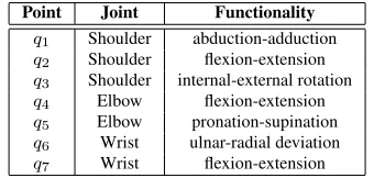
The most common model of the human arm is 7 DoFs as shown in Figure 4 consisting of the shoulder ball-and-socket joint with rotation axes for abduction-adduction (q1), flexion-extension (q2), and
internal-external rotation (q3) of the upper arm, the
flexion-Al-Kaff Low-Cost 3D Vision Based System for Post-Stroke Arm Rehabilitation using RGB-D Camera 4
Figure 3:Skeleton Structure of the Human Arm
extension (q4), and pronation-supination (q5) of the forearm and the wrist double-hinge joint with rota-tion axes for ulnar-radial deviarota-tion (q6), and flexion-extension (q7) of the hand, which are shown in Table 1.
Figure 4:Simplified human arm kinematics using 7 DoFs
Table 1:WEIGHT OF BODY SEGMENTS
Point Joint Functionality q1 Shoulder abduction-adduction q2 Shoulder flexion-extension q3 Shoulder internal-external rotation q4 Elbow flexion-extension q5 Elbow pronation-supination q6 Wrist ulnar-radial deviation q7 Wrist flexion-extension
In this work, the human arm motion is considered as a combination of the shoulder and the elbow mo-tion. The shoulder motion is composed of elemen-tary motions in theglenohumeral,scapulothoracic,
sternoclavicular, andacromioclavicularjoint [22]. The elbow joint is understood as a uniaxial joint con-necting the ulna with the humerus and the radius
with thehumerus. These two joints allow the elbow flexion and extension [13] and are modeled as a single rotation as shown in Figure 5.
Figure 5:Shoulder-Elbow movement
4.2 The Geometric and Inertial Characteristics of the Human Arm
de-veloped and used in wide variety of techniques and applications. In 1983, Zatsiorsky obtained by means of a gamma-ray scanning technique, the relative body segment masses, center of mass (CM)positions, and radii of gyration for samples of college-aged Caucasian males and females. In addition, the parametersB0,B1
andB2was determined of each body segment [20],[21]. The equation of estimating the mass of the body seg-ments is given as follow:
mi=B0+B1×m+B2×ν (1)
where, m(kg)is the total mass of body, ν(cm)is the height of the body and the parametersB0,B1 and B2are explained in Table 2.
Table 2: B0, B1 ANDB2 PARAMETERS OF THE MASS OF BODY SEGMENTS [20],[21]
Cadaver B0 B1 B2
Head + Neck 1.2960 0.01710 0.01430 Upper Arm 0.2500 0.03012 -0.00270 Forearm 0.3185 0.01445 -0.00114 Hand -0.1165 0.00360 0.00175 Leg -0.0829 0.00770 0.00730 Shank -1.5920 0.03616 0.01210 Thigh -2.6490 0.14630 0.01370 Trunk . . . . Upper part of the Trunk 8.2144 0.1862 -0.05480 Middle part of the Trunk 7.1810 0.2234 -0.06630 Lower part of the Trunk -7.4980 0.0976 0.04896
Focusing on the upper arm and forearm segment, and considering the mass of the forearm and the hand as one rigid segment, so the mass for each one can be calculated as follow:
mupper= (0.25) + (0.03012×m) + ((−0.0027)×ν) (2)
mf ore = (0.3185 + 0.01445×m+ (−0.00114)×ν) + ((−0.1165) + (0.0036×m) + (0.00175×ν))
(3)
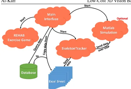
5 System Structure
The proposed Human Arm Tracker System consists of three parts:P atient−Interf ace,SkeletonT racker, andT herapist−Interf ace. Figure 6 shows the dia-gram of the system structure. Generally the patient is sitting in front of the Patient-Interface (Virtual Reality System) and the Kinect sensors. The patient is trying to perform the exercises that are shown in the screen.
During this motion, the Kinect sensors detect the arm joints and send the positions to theSkeletonT racker
application which in turn performs calculations to esti-mate more data that helps the therapist in the analysis process. TheSkeletonT rackeralso sends this data to a temporary file over UDP packets.
On the other hand, the T herapist−Interf ace
controls all other applications and takes a copy of the patient data from the temporary file to a permanent database. TheT herapist−Interf aceallows the ther-apist to monitor the motion of the arm and the data got during the exercise.
In addition, the therapist can search for all the data of the patient in his history file and estimates the per-formance of the arm during the motion in terms of ve-locities and energies. The three part of the system will be explained in details in the following subsections.
5.1 Patient Interface
This framework includes a 3D game as interactive exer-cise to motivate the patient and to estimate the arm data from it. In this game, the patient controls a character appears in the screen using the Kinect sensor, and the patient should follow a moving target which is located on a table in front of the character.
5.2 SkeletonTracker
This part is considered as the core of our rehabilita-tion system, which is able to track the human arm and estimates the 3D joint positions (shoulder, elbowand
wrist). Figure 7 shows the human arm joints and seg-ments obtained by theSkeletonT rackerapplication.
5.3 Therapist Interface (Main interface)
This part gives the therapist full monitoring of the pa-tient motion; furthermore it allows the therapist to trol all the other applications. Generally this part con-sists of three forms: New User, Existing User, and Search form. A diagram of the main tasks of the Therapist-Interface is shown in Figure 8.
Al-Kaff Low-Cost 3D Vision Based System for Post-Stroke Arm Rehabilitation using RGB-D Camera 6
Figure 6:System Diagram
Figure 7:SkeletonT rackerForm
In addition to that the data of the arm are copied from the temporary file (.csv) into the patient record in the main database.
2. Search Form: This form allows the therapist to query about the patient data from his record file. The therapist is basically allowed to search accord-ing to the patient record number, and the therapist has also the ability to filter his search either by date or the Level of the exercise. Moreover the therapist can estimate the average velocity and the average energy of each segment of the arm of the selected search.
In this form also, it is possible to print a report
showing the patient personal information and the data estimated during the motion such as the in-stant velocities and inin-stant energies, with a final summary of the arm data. Figure 10 shows the Search Form.
6 Virtual Reality (REHAB Game)
More prosaically,V irtualRealitycan be described as a computer technology which allows to create detailed a realistic 2D or 3D environments of particular real life or imaginary situations.
re-Figure 8:The tasks of theT herapist−Interf ace(Main-Interface)
Figure 9:New User form
Figure 10:Search form
training coordinated movement patterns.
6.1 Virtual Reality and Rehabilitation
The use of a virtual reality technology is used in a wide range for the training of motor tasks. It is cur-rently being explored in several areas of rehabilitation.
Virtual reality training has been used for children with Cerebral Palsy to enhance spatial awareness [16] and to successfully teach these children to operate motorized wheelchairs [8].
In addition virtual reality based rehabilitation sys-tems have several advantages. Similar to computer games VR rehab exercises can be made to be engaging, which is important in terms of the patient motivation [17].
6.2 Unity 3D Game Engine
Unity 3D is a fully integrated development engine that provides rich out-of-the-box functionality to create games and other interactive 3D content. Unity is used to assemble assets into scenes and environments; add physics; simultaneously play test and edit the game and publish to different platforms (PC, Web, iOS, Android, Wii, PS3 and Xbox 360) [6].
6.3 Game Description
REHAB game is a 3D simulation game attached to the
SkeletalT rackerapplication, which is able to detect the motion of the patient arm in 3D space. This simula-tion gives the patient a comfortable and familiar sense that encourages him to improve his efforts, and also it is useful in case of rehabilitation for children where can provide an interesting time during the exercises.
REHAB game has one scenario which simulates an environment of a kitchen, where the human character
”Sara”can only move her upper limbs. This scenario divided into three levels of difficulty, we create just one scenario not to confuse the patient and make him famil-iar and confident in each level, while each level provide more difficulty than the previous one. This difficulty aims to improve the patient’s motion performance.
For each level the patient should put a ”Cup” at-tached to the character hand on a moving colorful
”T arget”. When the ”Cup” collides or touches the
”T arget”, it moves to a different position and the pa-tient needs again to touch it again, and so on. The game has no time calculation, it ends when all the targets are collided.
6.4 Aims of the game levels
The First level allows the patient a free arm motion, mostly it is a vertical motion to followtentargets -one each time- located in a fixed position. Figure 11 (Up) shows the first level scene. This task focuses on im-proving the strength of the shoulder joint.
-Al-Kaff Low-Cost 3D Vision Based System for Post-Stroke Arm Rehabilitation using RGB-D Camera 8
Figure 11:REHAB game: (Up) First Level, (Middle) Second Level, (Down) Third Level
one each time- which it has a random position as shown in Figure 11 (Middle). In this level we focus on the strength of both shoulder and elbow joints.
The Third level is almost similar in concept of mo-tion to the Second level. In which, the patient should follow the 20 targets. But in this level some obstacles were added in the motion space in order to increase the complexity.
While the patient is following the targets, he should avoid touching the obstacles. In this level there is a ”Count” and ”F oul” screens, where the”F ouls”
refers to the number of obstacles collided and the
”Count” is the number of target followed. Finally, the”score” is obtained by subtracting the number of
”F ouls”from the total number of”Counts”. This is shown in Figure 11 (Down).
7 Experimental Results
The proposed system explained in the previous sections has been tested and verified with data gathered from experiments performed on 120 volunteers. All exper-iments were performed using Intel core i7-2600 at 3.4 GHz processor, and 8 GB of memory and AMD Radeon graphics card with 3.5 GB of memory.
Each one performed the three levels of the game in different positions with or without additional weight. Table 3 shows the information (Gender, Weight, and Height) of some of the patients who performed the ex-periments.
Table 3:PATIENTS INFORMATION
Patient No. Gender Age Weight(Kg) Height(cm)
1 M 27 64 170
2 F 28 51 164
3 M 29 60 169
4 M 28 62 171
5 M 24 68 180
6 M 28 66 178
7 M 33 69 175
8 M 30 64 184
9 F 27 80 175
10 F 35 58 170
The following figures show various graphs repre-senting the data of patient motion during performing the exercise of Level 3.
7.1 Elbow and Wrist joints positions
Focusing on the human arm, the 3D joint position (x, y, z) can be represented as follows:
Shoulderjointposition= (Shx, Shy, Shz) Elbowjointposition= (Elx, Ely, Elz) W ristjointposition= (W tx, W ty, W tz)
(4)
Figure 12 shows the joints positions in 3D space while motion.
7.2 Centers of Mass Positions
Figure 12:Joints Positions: (Up) Shoulder positions, (Middle) Elbow positions, (Down) Wrist positions - (Blue: x position),
(Green: y position), (Red: z position)
1. The position of the center of mass of the upper arm
Cuis given as(Cux,Cuy,Cuz), where
Cux= Shx+2Elx
Cuy=
Shy+Ely 2
Cuz= Shz+2Elz
(5)
2. The position of center of mass of the forearmCf
has some considerations; because of the elimina-tion of the Kinect in detecelimina-tion of the hand, the sys-tem cannot calculate the real center of mass of the forearm.
With the help of previous Anatomy studies [1] [10], and by considering that the hand and the fore-arm as one rigid segment, a 7cmwas added to the
xposition of wrist joint, therefor a relative position ofCf will be (Cfx,Cfy,Cfz), where:
Cfx= Elx+W t2 x+7
Cfy =Ely+2W ty
Cfx= Elz+2W tz
(6)
In Figure 13 the 3D positions of the centers of mass for upper and forearm are shown.
Figure 13:center of mass Positions: (Up) Upper arm, (Down) Forearm - (Blue: x position), (Green: y position), (Red: z position)
7.3 Velocities
One of the major aims of this system is to estimate the velocity of the arm segments. Therefore, the velocity of the upper and forearm is given as follows:
V el(Cu) =
q
(Cux−Cuxo)2+ (Cuy−Cuyo)2+ (Cuz−Cuzo)2
dt
(7)
V el(Cf) =
q
(Cfx−Cfxo)
2
+ (Cfy−Cfyo)
2
+ (Cfz−Cfzo)
2
dt
(8)
Al-Kaff Low-Cost 3D Vision Based System for Post-Stroke Arm Rehabilitation using RGB-D Camera 10
Figure 14:Velocities (cm/sec) of the center of mass of arm segments: (Up) Forearm, (Down) Upper arm
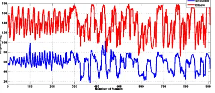
7.4 Additional Data Representation
In the following figures 15 and 16, some additional data are represented, these data are the angles of shoul-der and elbow joints in (Degree), and the angular ve-locities of each arm segment (upper and forearm) in (Deg./Sec).
Figure 15: Joints Angles (degrees) - (Blue: Shoulder joint), (Red: Elbow joint)
8 Conclusion and Future Work
8.1 Conclusion
In this paper, the main objective is to develop a low cost and accurate vision-based system to characterize the human arm motion for rehabilitation issues.
To achieve this, a markerless human motion capture system was applied by using a Microsoft Kinect sensor as data input.
Figure 16:Angular Velocities (Deg./Sec): (Up) Forearm, (Down) Upper arm
The proposed allows to estimate the arm joints po-sitions, velocities, angles, the positions of the centers of mass of arm segments (upper and forearm) and its ve-locities and the angular velocity of each segment in the 3D space.
Furthermore the system is able to calculate the mass of the arm segments with respect to the total weight and height of the human body.
Finally it gives the results to the therapist in terms of velocities and energies.
From the experiments, we found that performing the exercises in a low intensity light helps to eliminate the noise provided by the Kinect, which leads to obtain more accurate data. On other hand taking the reading every 5 frames minimize the probability of having this noise.
8.2 Future Work
Future work planned for this research consists of two directions.
The first direction includes developing the system to be able to characterize the human lower limb motion by detecting the leg joints (hip, knee, and ankle) and its positions and velocities.
Till now the Kinect sensor is not able to detect the human hand and its fingers joints, therefor with the new versions of Kinect, we planned to improve this system to estimate the hand motion and determine its data for the rehabilitation issues.
aimed to integrate this vision based system with inertial sensors to obtain more accurate and more satisfactory results.
Moreover, it is planned to design more 3D games to cover the all possible exercises in order to complete the rehabilitation operation.
References
[1] A. K. Agnihotri, B. Purwar, N. Jeebun, and S. Agnihotri. Determination of sex by hand dimen-sions. The Internet Journal of Forensic Science, 1(2), 2005.
[2] Attygalle, S., Duff, M., Rikakis, T., and He, J. Low-cost, at-home assessment system with wii re-mote based motion capture. InVirtual Rehabilita-tion, 2008, pages 168–174. IEEE, 2008.
[3] Balasubramanian, S., Wei, R., Perez, M., Shepard, B., Koeneman, J., Koeneman, E., and He, J. Ru-pert: An exoskeleton robot for assisting rehabili-tation of arm functions. InVirtual Rehabilitation, 2008, pages 163–167. IEEE, 2008.
[4] Cameirão, M. S., Oller, E. D., Verschure, P. F., et al. Using a multi-task adaptive vr system for up-per limb rehabilitation in the acute phase of stroke. InVirtual Rehabilitation, 2008, pages 2–7. IEEE, 2008.
[5] Chan, M., Giddings, D., Chandler, C., Craggs, C., Plant, R., and Day, M. An experimentally con-firmed statistical model on arm movement. Hu-man movement science, 22(6):631–648, 2004.
[6] Creighton, R. H. Unity 3D game development by example: beginner’s guide. Packt Publ., Birming-ham [u.a., 2010.
[7] Dellon, B. and Matsuoka, Y. Feedback distor-tion to augment controllability of human limb mo-tion. InVirtual Rehabilitation, 2008, pages 22–27. IEEE, 2008.
[8] DP. Inman, J. Peaks, K. Loge, and V. Chen. Teach-ing orthopedically impaired children to drive mo-torized wheelchairs in virtual reality. InCenter on Disabilities Virtual Reality Conference. 1994.
[9] Gams, A. and Lenar˘ci˘c, J. Humanoid arm kine-matic modeling and trajectory generation. In Biomedical Robotics and Biomechatronics, 2006. BioRob 2006. The First IEEE/RAS-EMBS Inter-national Conference on, pages 301–305. IEEE, 2006.
[10] Hans-Martin Schmidt and Ulrich Lanz. Surgical Anatomy of the Hand. 1 edition, 2003.
[11] Kathryn LaBelle. Evaluation of Kinect Joint Tracking for Clinical and in-home Stroke Reha-bilitation Tools. PhD thesis, Notre Dame, Indiana, 2011.
[12] Lanfermann, G., te Vrugt, J., Timmermans, A., Bongers, E., Lambert, N., and van Acht, V. Philips stroke rehabilitation exerciser. Technical Aids for Rehabilitation-TAR, 2007.
[13] Lenar˘ci˘c, J. and Staniši´c, M. A humanoid shoul-der complex and the humeral pointing kinematics. Robotics and Automation, IEEE Transactions on, 19(3):499–506, 2003.
[14] Microsoft Corporation. Kinect xbox
360:http://www.xbox.com/en-us/xbox-360/accessories/kinect, 2015.
[15] Microsoft Research. Kinect for Windows SDK Beta: Programming Guide. Microsoft Co., beta edition, 2014.
[16] Nigel Foreman, Paul Wilson, and Danae Stan-ton. Vr and spatial awareness in disabled children. Communications of the ACM, 40(8):76–77, 1997.
[17] Popescu, V. G., Burdea, G. C., Bouzit, M., and Hentz, V. R. A virtual-reality-based telerehabil-itation system with force feedback. Information Technology in Biomedicine, IEEE Transactions on, 4(1):45–51, 2000.
[18] Prange, G., Krabben, T., Molier, B., van der Kooij, H., and Jannink, M. A low-tech virtual reality application for training of upper extremity motor function in neurorehabilitation. InVirtual Reha-bilitation, 2008, pages 8–12. IEEE, 2008.
[19] Schönauer, C., Pintaric, T., Kaufmann, H., Jansen-Kosterink, S., and Vollenbroek-Hutten, M. Chronic pain rehabilitation with a serious game using multimodal input. InVirtual Rehabilitation (ICVR), 2011 International Conference on, pages 1–8. IEEE.
[20] V. Zatsiorsky and V. Seluyanov. The mass and inertia characteristics of the main segments of the human body. Biomechanics VIII-B, 56(2):1152– 1159, 1983.
Al-Kaff Low-Cost 3D Vision Based System for Post-Stroke Arm Rehabilitation using RGB-D Camera 12
by means of the best predictive regression equa-tions.Biomechanics IX-B, pages 233–239, 1985.
[22] Vladimir M. Zatsiorsky. Kinematics of Human Motion. ilustrada edition, 1998.
[23] Webb, J. and Ashley, J. Beginning Kinect Pro-gramming with the Microsoft Kinect SDK. Apress, 2012.
[24] White, D., Burdick, K., Fulk, G., Searleman, J., and Carroll, J. A virtual reality application for stroke patient rehabilitation. InMechatronics and Automation, 2005 IEEE International Confer-ence, volume 2, pages 1081–1086. IEEE.

![Figure 2: Kinect Sensor Diagram [15]](https://thumb-us.123doks.com/thumbv2/123dok_us/8364684.1672969/3.612.305.523.131.250/figure-kinect-sensor-diagram.webp)
![Table 2: B0, B1 AND B2 PARAMETERS OF THE MASS OFBODY SEGMENTS [20],[21]](https://thumb-us.123doks.com/thumbv2/123dok_us/8364684.1672969/5.612.73.289.347.467/table-b-b-b-parameters-mass-ofbody-segments.webp)