Realization of Logic Gates Using
Mcculloch-Pitts Neuron Model
J.S.Srinivas Raju1, Satish Kumar2, L.V.S.S.Sai Sneha3
1
Assistant Professor, Electrical & Electronics Engineering, Universal College of Eng. & Tech. (AP), India
2
U.G Student, Electrical & Electronics Engineering, Universal College of Eng. & Tech. (AP), India
3
U.G Student, Electrical & Electronics Engineering, Universal College of Eng. & Tech. (AP), India
Abstract —Brain is the basic of human body which corresponds for all the functions. Neurons are responsible for the response of our body. Like the same way, artificial neurons are created which function as similar to that of biological brain. In this paper the response of the artificial neurons are obtained by using different threshold values and activation functions of logic gates. In this paper McCulloch-Pitts model is applied for the purpose of realization of logic gates.
Keywords —Artificial Neuron, Activation function, Weights, Logic gates. Etc…
I. INTRODUCTION
The first formal definition of a synthetic neuron model based on the highly simplified considerations of the biological model described was formulated by McCulloch and Pitts in 1943.They drew on three sources: knowledge of the basic physiology and function of neurons in the brain; the formal analysis of propositional logic due to Russell and Whitehead; and Turing's theory of computation. They proposed a model of artificial neurons in which each neuron is characterized as being "on" or "off," with a switch to "on" occurring in response to stimulation by a sufficient number of neighbouring neurons. The state of a neuron was conceived of as "factually equivalent to a proposition which proposed its adequate stimulus." They showed, for example, that any computable function could be computed by some network of connected neurons, and that all the logical connectives could be implemented by simple net structures. [1]
II. McCULLOCH PITTS MODEL
Every neuron model consists of a processing element with synaptic input connection and a single input. The "neurons" operated under the following
assumptions:-i. They are binary devices (Vi = [0,1])
ii. Each neuron has a fixed threshold, theta values. iii. The neuron receives inputs from excitatory
synapses, all having identical weights.
iv. Inhibitory inputs have an absolute veto power over any excitatory inputs.
v. At each time step the neurons are simultaneously (synchronously) updated by summing the weighted excitatory inputs and setting the output (Vi) to 1 if the sum is greater than or equal to the threshold and if the neuron receives no inhibitory input.
Its architecture is shown by:
Fig-1: Architecture of McCulloch-Pitts Model
From the above fig, the connected path are of two types: excitatory or inhibitory. Excitatory have positive weight and which denoted by “w” and inhibitory have negative weight and which is denoted by “p”. The neuron fires if the net input to the neuron is greater than threshold. The threshold is set so that the inhibition is absolute, because, non-zero inhibitory input will prevent the neuron from firing. It takes only step for a signal to pass over one connection link. In this “y” is taken as output and X1, X2…………Xn (excitatory) & Xn+1, Xn+2……., Xn+m (inhibitory) are taken as input signals.
The McCULLOCH Pitts neuron Y has the activation function: F (yin) = 1 if y-in ≥ Ѳ
0 if y-in < Ѳ
Where, Ѳ=threshold Y=net output
By using MCCULLOCH Pitts model we are going to solve the following logic gates.
i. OR Gate ii. NOT Gate iii. AND Gate iv. NAND Gate v. XOR Gate vi. NOR Gate
A. OR GATE
inputs to the gate are high (1).If both inputs are low the result is low (0)[1]. A plus (+) is used to show the or operation. [2] Its block diagram and truth table is shown by:
Table -1: Truth table Fig -2: OR Gate
IMPLIMENTATION OF MCCULLOCH PITTS MODEL:
Fig -3: Architecture of OR Gate
The threshold for the unit is 3. [3] The net input is Yin=3A+3B. The output is given by
Y=f (Yin) = 1 if Yin≥3 0 if Yin<3
RESULTS:
B. NOT GATE
Paragraph It’s a logic gate which also known as inverter. It implements the logic negation. [4] If the input is low the output is high and vice versa. It takes only one input. The truth table and symbol are shown below. The threshold value is 1.
Table -2: Truth table Fig -4: NOT Gate
IMPLIMENTATION OF MCCULLOCH PITTS
MODEL:
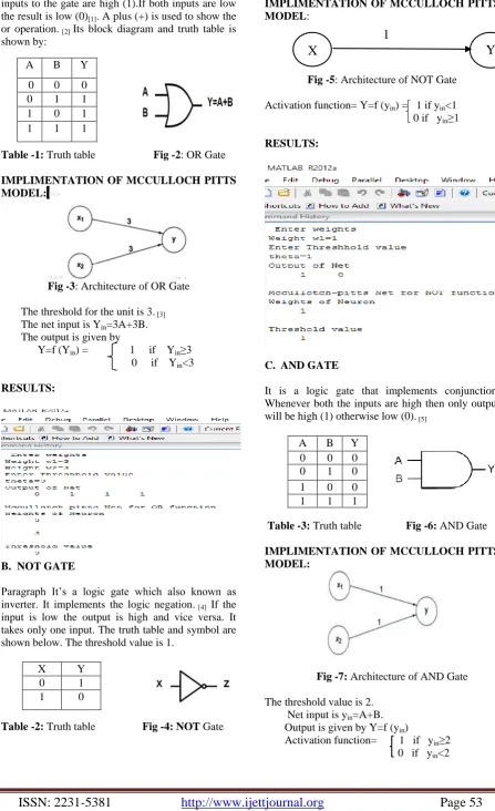
Fig -5: Architecture of NOT Gate
Activation function= Y=f (yin) = 1 if yin<1 0 if yin≥1
RESULTS:
C. AND GATE
It is a logic gate that implements conjunction. Whenever both the inputs are high then only output will be high (1) otherwise low (0). [5]
Table -3: Truth table Fig -6: AND Gate
IMPLIMENTATION OF MCCULLOCH PITTS MODEL:
Fig -7: Architecture of AND Gate
The threshold value is 2. Net input is yin=A+B. Output is given by Y=f (yin)
Activation function= 1 if yin≥2 0 if y <2
A B Y
0 0 0 0 1 1 1 0 1 1 1 1
X Y
0 1
1 0
A B Y 0 0 0 0 1 0 1 0 0 1 1 1
X
Y
RESULTS:
D. NAND GATE
It is nothing but combination of AND and NOT gate. So we can say that in case of NAND gate the NOT gate just inverts the output of the AND gate. So the output of this gate is 1 at all the times except when both inputs are 1, at that instant the output is 0. It is one of the universal gate. It is called so because any of the three basic gates can be obtained by it. [6]
Table-4: Truth table Fig -8: NAND Gate
IMPLIMENTATION OF MCCULLOCH PITTS MODEL:
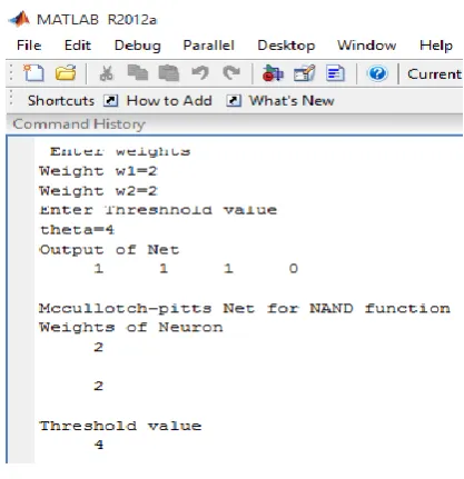
Fig -9: Architecture of NAND Gate
Threshold value is 4 Net input is yin=x1-x2. Output activation function is y= f (yin) = 1 if yin≥4 0 if yin <4.
RESULTS:
E. XOR GATE
It is sometimes called as XOR gate or exclusive or gate. It gives a true output when the number of true inputs is odd. If both the inputs are true and both are false then the output is false. These are used to implement binary addition in computers. [7] The truth table and symbol are shown below.
Table-5: Truth table Fig -10: XOR Gate
IMPLIMENTATION OF MCCULLOCH PITTS
MODEL:
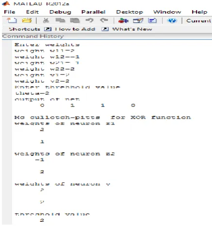
Fig -11: Architecture of XOR Gate
Threshold value=1
Activation function= y =f (yin) = 1 if yin≥1 0 if yin<1
A B Y
0 0 1
0 1 1
1 0 1
1 1 0
X1 X2 Y
0 0 0
0 1 1
1 0 1
RESULTS:
F. NOR GATE
It is a digital logic gate that implements logic NOR. It behaves according to the truth table. If both the inputs are low then it gives a high output and if either of the input is high then output is low. This can be combined to generate any other logical functions. It shares this property with the NAND gate. [8][9]
Table-6: Truth table Fig -12: NOR Gate
IMPLIMENTATION OF MCCULLOCH PITTS
MODEL:
Fig -13: Architecture of NOR Gate
Threshold value=1
Activation function= 1 if yin ≥ 1 0 if yin <1
RESULTS:
III. LIMITATIONS OF MCCMODEL:
i. Weights and thresholds are analytically determined.
ii. Very difficult to minimize size of a network. iii.
IV. CONCLUSIONS
Most of the work is carried on the basis of MCP model for observing the nature of logic gates like OR, AND, NOT, NAND, NOR, XOR with variable threshold conditions and for variable weights. The logic gate performances by using MCP model easily process of making and braking connections in different algorithms like Back Propagation Neural Network solutions and solution of Hebb nets for Linear Separability.
REFERENCES
[1] Neural Networks, Fuzzy Logic, and Genetic Algorithms by S.Rajasekharan and G.A Vijayalakshmi Pai.
[2] OR GATE, Hyperphysics.phy-astr.gsu.edu.retrive2012-09-24 [3] http://williams.comp.ncat.edu/COMP370/LogicGates. [4] pdf
[5] Mano, M.Morris and Charles R.Kine. Logic and Computer design Fundamentals, Third edition .Prentice Hall, and 2004.p.73
[6] Mano, M.Morris and Charles R.Kine. Logic and Computer design Fundamentals, Third edition .Prentice Hall, and 2004.p.73
[7] http://electricalstudy.sarutech.com/nand- gate/index.html
[8] Fletcher, William (1980). An engineering approach to digital design. Prentice Hall.p.98 ISBN 0-13-277699-5
[9] Mano, M.Morris and Charles R.Kine. Logic and Computer design Fundamentals, Third edition .Prentice Hall, and 2004.p.73
[10]The McCULLOCH- Pitts Model by Samantha Hayman.
A B Y
0 0 1
0 1 0
1 0 0
BIOGRAPHIES
J.S.Srinivas Raju was born on 15th July 1981 in Narasarao Peta. He is now perusing his PhD from JNTUK. He completed his B.Tech and M.tech from JNTUK. He is now working as a associate professor in EEE Department of Universal College Of Engineering and Technology. His areas of interests are power systems and AI techniques application to power system optimization.
Satish Kumar was born on 29th April
1995 in Patna, (Bihar). He is now perusing his B.tech from electrical & electronic stream in Universal college of Engg. & Technology, Guntur (affiliated to JNTUK, Kakinada and approved by AICTE New Delhi).He completed his SSC from Park Mount Public School, Patna (Bihar) &HSC from R.N College Hajipur (Bihar).
Lakkaraju.V.S.S.Sai Sneha was born on
15th November 1996 in Nuthakki (AP).
She is now perusing her B.tech from
Universal College of Engg. &
Technology, Guntur (affiliated to JNTUK,
Kakinada and approved by AICTE New Delhi). She completed her SSC from Vijnana Vihara School, Nuthakki. And
HSC from Harika Junior College,