Experimental Conditions for Electron Bernstein Wave Heating
Using EC Waves Injected from High-Field Side in CHS
Yasuo YOSHIMURA, Kazunobu NAGASAKI
1), Sergi FERRANDO-MARGALET,
Tsuyoshi AKIYAMA, Mitsutaka ISOBE, Akihiro SHIMIZU, Chihiro SUZUKI,
Chihiro TAKAHASHI, Kenichi NAGAOKA, Shin NISHIMURA, Takashi MINAMI,
Keisuke MATSUOKA, Shoichi OKAMURA, CHS group, Shin KUBO, Takashi SHIMOZUMA,
Hiroe IGAMI, Hiromi TAKAHASHI and Takashi MUTOH
National Institute for Fusion Science, Toki 509-5292, Japan
1)Institute of Advanced Energy, Kyoto University, Uji 611-0011, Japan (Received 16 November 2007/Accepted 13 February 2008)
In the compact helical system (CHS), electron heating by electron Bernstein waves (EBWs) was experi-mentally investigated to study a technique for high-density plasma heating over cutoffdensity. The EBWs are excited through a mode conversion process by X-mode waves injected to plasmas from the high-field side. In the experiment, within the range of an oblique EC-wave beam injection angle, evident heating effect was observed. The dependences of the heating effect on the wave’s toroidal injection direction and polarization show that the absorption of the mode-converted EBWs should be the cause of the plasma heating effect.
c
2008 The Japan Society of Plasma Science and Nuclear Fusion Research
Keywords: electron Bernstein wave, EBW, slow X-B, high-density plasma heating, high-field side injection, ECH, CHS
DOI: 10.1585/pfr.3.S1076
1. Introduction
Electromagnetic (EM) plasma waves such as ordinary (O) and extraordinary (X) mode waves suffer cutoff in high-density plasmas, and the EM plasma waves cannot contribute to electron heating over the cutoffdensity. On the other hand, electron Bernstein waves (EBWs) have ad-vantages, such as absence of any density limit and strong absorption even in low-temperature plasmas. Since the EBWs are a type of electrostatic waves in plasmas, they have to be excited by mode conversion processes by in-jected EM-waves. The following three types of mode con-version process are considered: the so-called fast X-B, slow X-B, and O-X-B. Among them, the O-X-B mode conversion technique [1] has been considered as the most promising approach for heating overdense plasmas, be-cause ECH systems including steerable beam injection an-tennas from the low-field side are technically available on existing tokamaks and helical systems [2–6].
Compared with the O-X-B process, the slow X-B pro-cess can more easily realize mode conversion to EBWs, since the difficulty of achieving high-O-X mode conver-sion efficiency does not exist. When injected through a fundamental resonance layer from the high-field side (called the X-B access window), the X-mode EC-waves propagate into the plasmas, and are mode converted into the EBWs at the upper hybrid resonance (UHR) layer. The EBWs are absorbed at the Doppler-shifted electron
cy-author’s e-mail: [email protected]
clotron resonance, resulting in plasma heating. When in-jected away from the X-B access window, the X-mode EC-waves suffer right-hand cutoff, and cannot heat the plasmas effectively.
Thus far in the WT-3 tokamak, using an O-X polariza-tion twister installed at the high-field side, EBW heating was performed by injecting O-mode EC-waves to avoid the right-hand cutoffof X-mode waves [7]. Also in the COMPASS-D tokamak, electron heating and current drive by the X-mode injection from the high-field side were demonstrated [8]. However, generally the EC wave injec-tion from the high-field side (i.e., from the inner side of the torus for tokamaks) accompanies difficulties, due to in-sufficient availability of space for installing an EC-wave injection antenna system or a reflection mirror.
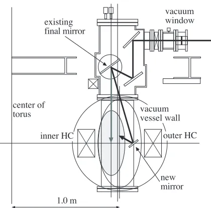
The compact helical system (CHS) [9] provides a good opportunity for investigating the slow X-B heating scenario experimentally, since due to its two-helical coils generating plasma confining magnetic field, it has two X-B access windows in a poloidal cross section. For example, in the vertically elongated poloidal cross section, one win-dow is at the inner side of the torus in a position similar to that in the tokamaks, whereas the other one is at the outer side where a wider space is available for installing an elaborate structure such as the steerable mirror for a beam direction scan, as seen in Fig. 1. By installing a mirror in-side the CHS vacuum vessel, the slow X-B experiments were conducted [10]. In this paper, the dependences of the slow X-B heating effect on the wave’s injection direction
c
2008 The Japan Society of Plasma
Fig. 1 A drawing of poloidal cross section of the CHS devise and the EC-wave beam injection system. The focused beam is injected to the plasmas using a set of inner-vessel mirrors. The abbreviation HC denotes the helical coil. The gray area denotes the plasma schematically.
and polarization are introduced as follows. Experimental setups such as the CHS and the EC wave injection system are briefly described in Sec. 2. The experimental results of EC-wave beam direction and polarization scans for slow X-B heating are presented in Sec. 3. In Sec. 4, the content of this paper is summarized.
2. Experimental Setup
The CHS is a helical device with the toroidal period numberm=8 and polarityl=2. The magnetic field struc-ture with the rotational transform for plasma confinement is completely generated by external coils, such as a couple of helical coils and three pairs of poloidal coils. The ma-jor radius of the CHS plasma is about 1.0 m, the averaged minor radius is 0.2 m, and thus the aspect ratio is 5. The magnetic field at the plasma axis can be set up to approxi-mately 2.0 T.
The ECH system on CHS furnishes two gyrotrons. The operating frequency of one of them is 54.5 GHz, and that of the other is 106.4 GHz. The slow X-B experiments described in this paper were performed with the 54.5-GHz one. The transmission line for the 54.5-GHz waves was constructed as a quasi-optical Gaussian beam transmission system using 12 mirrors−three of them inside the CHS vacuum vessel, and two of themλ/4 andλ/8 grating po-larizers. The three inner-vessel mirrors are installed on the top port, and the final plane mirror can be tilted 2-dimensionally so that the direction of the injected EC-wave beam can be scanned in both the poloidal and toroidal di-rections. A beam injection from the top port means an injection from the low-field side. The injected EC-wave
beams are circularly focused, and have a beam size (1/e ra-dius of the electric field amplitude) of 22 mm at the equa-torial plane. An example of the beam path injected by the existing three inner-vessel mirrors is indicated by a gray bold line with an arrowhead in Fig. 1. Using the two po-larizers installed on the transmission line, the polarization of EC-wave beams can be varied arbitrarily. The total dis-tance between the gyrotron output window and the CHS plasma center is approximately 17 m. The maximum in-jection power and pulse length of the 54.5-GHz waves in the CHS vacuum vessel are 415 kW and 100 ms, respec-tively.
In addition to the existing EC-wave power injection system described above, a new plane mirror was installed inside the vacuum vessel between the plasma and outer he-lical coil. By directing the EC-wave beam from the ex-isting antenna system to the new mirror, an injection of 54.5-GHz EC-wave from the high-field side becomes pos-sible. The tilting angle of the mirror in the vertical di-rection was fixed during the experiment, and the reflected beam direction was 39 deg upward. The beam direction can be changed toroidally by rotating the mirror around its vertical axis.
3. Dependences of the Heating E
ff
ect
on the EC-Wave Beam Direction
and Polarization
3.1
Experimental configuration
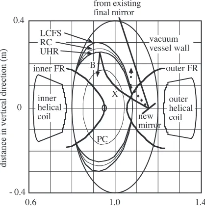
Figure 2 shows the experimental configuration at a vertically elongated plasma poloidal cross section in a typ-ical slow X-B discharge. The magnetic field of CHS is high near the helical coils, and it decreases with the dis-tance from the helical coils in a saddle-shape distribution. The magnetic field at the plasma axis is set 1.95 T, i.e., the fundamental resonance field for the 54.5-GHz waves. The magnetic axisRaxis set at 0.95 m. The fundamental reso-nance (FR) layers are seen as bold hyperbola-like curves. One of the FR layers lies on the magnetic axis, and the other exists in the peripheral region of the plasma.
The high-density plasmas are sustained with the neu-tral beam injection (NBI). The core region of the plasma volume is enclosed with the plasma cutoff(PC) layer. The O-mode waves are reflected at the PC layer so that they cannot propagate inside the PC layer. The X-mode waves propagate into the plasmas when they are injected from the high-field side within a region (X-B access window) bounded by the last-closed flux surface (LCFS) and FR layer, except the density is much higher to have a left-hand cutofflayer. The X-mode waves suffer right-hand cutoff (RC) when they are injected out of the X-B access win-dow.
X-B access window appears like a winding belt with its right-side up.
In Fig. 2, the EC wave’s trajectories (projections on the poloidal cross section) injected using the new mirror are shown schematically. The bold lines are those for X-B mode conversion, and the dotted lines are those for the waves reflected at the RC layer.
Fig. 2 An example of the experimental configuration of the slow X-B discharge. The abbreviations LCFS, RC, UHR, FR, PC, X and B denote last closed flux surface, right-hand cutoff, upper-hybrid resonance, fundamental resonance, plasma cutoff, X-mode and the electron Bernstein mode, respectively.
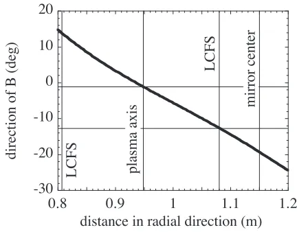
Fig. 3 A schematic drawing showing the definitions of the up-ward angle (fixed at 39 deg in this paper) and the toroidal angle for the EC-wave beam injection using the new plane mirror. A definition of the angle of the magnetic field line at the position of the center of the new mirror is also seen (−20 deg here) for example.
Figure 3 shows schematically the equatorial plane around the new plane mirror to clarify the definitions of the EC-wave beam injection angles and the magnetic-field direction, which is described below in the explanations of the experimental results.
3.2
Dependence on the EC-wave beam
direc-tion
The result from the toroidal scan of the EC-wave beam direction injected from the high-field side using the new mirror is plotted in Fig. 4. In the scan experiment, the EC-wave pulses were injected twice during each discharge. The first pulse generates the seed plasmas and the NB-power heats, and sustains the plasmas with the line-average electron density of 3-3.5×10¹⁹m−3at the second EC-wave injection timing. The second EC-wave pulse is applied to the NB-sustained plasmas. The plasma stored energyWp during the second EC-wave pulse divided by theWp just before the second pulse is plotted as a function of the EC-wave beam direction. The beam direction is the same for the first and second pulses. The positive (negative) sign of the toroidal injection angle suggests that the direction is right side (left side), looking from outside of the torus (see Fig. 3). Effective plasma generation and significant plasma heating occurred only with a toroidal injection an-gle larger than∼20 deg. Otherwise, the NB-power could not raise the seed plasmas. During the NB-power injection, the density was finite, but the plasma stored energy (or the electron temperature) was zero, i.e., the plasma could not overcome the radiation barrier. Due to the rather upward (39 deg) EC-wave beam injection from the new mirror, the beam path does not pass through the X-B access window when the beams are injected with a toroidal injection an-gle of around 0 deg (normal injection) or less. According to the definition of the vertical (orY-) axis of Fig. 4, the
Y-values for the toroidal injection angles less than 10 deg should be 0/0 and indefinite, but zero was plotted for con-venience sake to show the experimental injection angles.
On the other hand, with the injection angle larger than ∼20 deg, the EC-wave passes through the X-B access win-dow due to the toroidal distribution of the winwin-dow de-scribed in Sec. 3.1. Therefore, only with the toroidal in-jection angle larger than ∼20 deg, the slow X-B process works, and effective plasma heating occurs.
3.3
Dependence on the polarization of the
EC-wave
For an effective slow X-B mode conversion, injecting pure X-mode waves into plasmas from the high-field side is a key issue. To check the dependence of the slow X-B heat-ing effect on the polarization, the direction of linear polar-ization of the injected EC-waves was changed in a shot-by-shot manner. The plasma generation/heating scheme was the same as that described in Sec. 3.2. The toroidal and vertical injection angles of the EC-waves were fixed at 25.4 and 39 deg, respectively.
Figure 5 shows the variation of the magnetic field di-rection along the major radius axis. The definition of the angle of the magnetic field direction is shown in Fig. 3. Ob-serving from the outside of the torus, the toroidal direction is 0 deg, and the positive direction of the angle is coun-terclockwise. Because the plasma confining magnetic field structure, including the rotational transform, is completely generated by the external coils in the helical systems, the poloidal component of the magnetic field becomes larger with the minor radius. On the LCFS at the major radius axis of 1.08 m, the direction is −13 deg, and at the posi-tion of the center of the new plane mirror at 1.15 m, the direction is−20 deg.
In the case of EC-wave injection normal to the flux surfaces, Fig. 5 indicates a variation of the magnetic field direction along the EC-wave beam path. In that case, the O-mode injection is realized by setting the linear polariza-tion with the electric field oscillapolariza-tion in the direcpolariza-tion of −13 deg, and the X-mode by the polarization direction of 77 deg.
In the slow X-B heating experiment described in this paper, the EC-waves were obliquely injected so that the polarizations for the pure X- and O-mode waves were not linear. However, in this polarization scan experiment, the settings of the polarizer discs on the transmission line were those for the linear polarization in the case of the normal injection, and the linear polarization direction was roughly rotated by 30 deg, as the first step of the investigation of the effect of polarization.
The dependence of the heating effect on the linear po-larization direction is plotted in Fig. 6. The heating effect is evaluated by the same process, as in Fig. 4: with the plasma stored energy during EC-wave injection divided by that just before injection. Only at the polarization direction of−10 deg, where the X-mode component is considered
Fig. 5 Variation of the magnetic field direction along the major radius axis.
Fig. 6 Dependence of the heating effect on the linear polariza-tion direcpolariza-tion of the EC-waves.
poor even in the oblique injection case, the heating effect disappeared. This plot shows that the X-mode component is important, and that the mode conversion to the EBWs would be the key for plasma heating. Setting pure X-mode polarization and making a systematic variation of its purity by elliptical polarization are left for the future work, and it would clarify the dependence.
3.4
Overdense plasma heating by slow X-B
technique
for plasma generation, and the second and third were ap-plied to the plasmas sustained with 845 kW power of one NBI. The plasma stored energy significantly increases with the second and the third injections of ECH power. The central electron temperature increases from about 1.0 to
Fig. 7 Waveforms of a slow X-B discharge with an overdense electron density. The horizontal line in the bottom col-umn for the line-average electron density denotes the plasma cutoff density 3.7×10¹⁹m−3 for the 54.5-GHz
EC-waves.
1.5 keV by the second injection and from about 0.6 to 1.2 keV by the third injection, while the line-average elec-tron density constantly increased during the plasma dura-tion. The increases in the plasma stored energy are then caused by increases in the electron temperature. At the third injection timing of the discharge, the line-average electron density reaches close to the O-mode cutoff den-sity of 3.7×10¹⁹m−3for the 54.5-GHz EC-waves.
The slow X-B heating is effective for the plasmas with densities much greater than the cutoff density. In the discharge of waveforms seen in Fig. 7, the heating procedure was nearly the same with the discharge de-scribed above, although the plasma was sustained with much higher power, i.e., 1.66 MW from two NBIs. The line-average electron density linearly increases during the discharge. At the second injection timing, the line-average electron density is around the cutoff, and at the third in-jection timing of the discharge, it becomes more than 1.5 times greater than the cutoff. Until just before the third injection, the plasma stored energy continuously decreases due to a decrease in the electron temperature exceeding the increase in the electron density. By the start of the third in-jection, the stored energy stops decreasing and the value is maintained, or starts increasing slightly. Here it should be noted that the raw data of the plasma stored energy in the CHS suffer meaningless fluctuations, thus the plotted data were “smoothed” to remove the fluctuations.
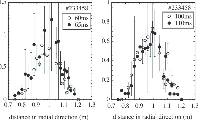
The electron temperature distributions measured with the Thomson scattering measurement are plotted in Fig. 8. The distributions are those at 60 ms (just before the second EC-wave injection), 65 ms (during the second injection), 100 ms (just before the third injection), and 110 ms (dur-ing the third injection). At the second injection tim(dur-ing,
the central electron temperature increases from about 0.8 to 1.2 keV by the EC-wave injection. At the third injection timing, only a slight decrease is recognized for 10 ms inter-val. Therefore, even for the plasmas with the density much higher than the cutoff, the slow X-B heating demonstrated its effectiveness by holding back the rapid decrease of the electron temperature.
The numerical calculations to confirm the realization of slow X-B heating in the CHS experimental configura-tion are under investigaconfigura-tion. Some of the results can be seen in the proceedings at the ITC/ISHWS2007 confer-ence [11] and the future extended paper of it.
4. Conclusions
In the CHS, the slow X-B heating technique was ex-perimentally investigated using an inner-vessel mirror that enabled the EC-wave beam injection to plasmas from the high-field side through the fundamental resonance layer. As a result of the beam direction scan, the plasma stored energy and electron temperature increased only when the EC-wave beams were injected through the X-B access win-dow. The scan of the linear polarization direction showed nearly O-mode polarization, i.e., the poor X-mode com-ponent had no heating effect. The slow X-B heating
tech-nique is effective for overdense plasmas with a density 1.5 times greater than the cutoff, meeting the expectation of applying this technique.
Acknowledgements
The authors would like to thank the CHS staff for conducting the CHS experiments. This study was per-formed under the framework of bidirectional collaborative research program between Kyoto University (Heliotron-J group) and NIFS (Code number: NIFS04KUHL005).
[1] J. Preinhaelter and V. Kopecky, J. Plasma Phys. 10, 1 (1973).
[2] H. P. Laquaet al., Phys. Rev. Lett.78, 3467 (1997). [3] H. P. Laquaet al., Nucl. Fusion43, 1324 (2003). [4] A. Muecket al., Fusion Sci. Tech.52, 221 (2007). [5] Y. Yoshimuraet al., Fusion Sci. Tech.52, 216 (2007). [6] H. Igamiet al., Rev. Sci. Inst.77, 10E931 (2006). [7] T. Maekawaet al., Phys. Rev. Lett.86, 3783 (2001). [8] V. Shevchenkoet al., Phys. Rev. Lett.89, 265005 (2002). [9] K. Matsuokaet al., Plasma Phys. Control. Fusion42, 1145
(2000).
[10] Y. Yoshimuraet al., Plasma Fusion Res.1, 053 (2006). [11] S. Ferrando-Margalet et al., presented in the ITC/