IJSRSET1626109 | Received : 03 Dec. 2016 | Accepted : 12 Dec. 2016 | November-December-2016 [(2) 6: 437-441]
© 2016 IJSRSET | Volume 2 | Issue 6 | Print ISSN: 2395-1990 | Online ISSN : 2394-4099 Themed Section: Engineering and Technology
437
Validation Simulations of a Bluff-Body Stabilised Flame
Combustion Process
Dr. R. Ravi Varma
Department of Civil Engineering, Geethanjali College of Engineering & Technology, Hyderabad, Telangana State, India
ABSTRACT
Experimental measurements of the temperature and chemical species mass concentrations are compared with predictions made by a commercial Computational Fluid Dynamics (CFD) package. The bluff body burner considered for this study is included in the library of test flames of the International Workshop on Measurement and Computation of Turbulent Non-premixed Flames (TNF). The unmixed bluff-body stabilised flame burner, which is representative of industrial designs, using a fuel of 1:1 volume ratio of methane and hydrogen was chosen. Four k-ε based turbulence models are examined. Four combustion models; the Eddy Break-Up model, the Adiabatic and Non-adiabatic Presumed Probability Density Function (PPDF) model, and the Laminar Flamelet model are studied. The benefits of the Laminar Flamelet model are illustrated with excellent results being obtained when it is used in conjunction with the Chen k-ε turbulence model. A detailed analysis comparing the merits of each of the modelling approaches is presented.
Keywords: Computational Fluid Dynamics, Bluff Body, Modeling
I.
INTRODUCTION
The Combustion Research Group in the School of Aerospace, Mechanical and Mechatronic Engineering at the University of Sydney has compiled a body of turbulent combustion experimental data [1].Their bluff-body burner provides a useful validation case for CFD because;
• it has a simple geometry and boundary conditions and bears close resemblance to practical combustors, • experimental mass fraction measurements of the
chemical species are available.
• a complex flow pattern, involving two recirculation zones, develops downstream of the bluff-body surface, providing a challenge for turbulence modelling,
• hydrogen is mixed with the methane fuel to minimise soot levels which eliminates uncertainties caused by radiative heat loss, enabling the combustion modelling to be examined in detail.
The simulations were performed using commercially available CFD package. The choice was based on familiarity with the package and it is widely used in
industry. The code has undergone extensive testing and its wide ranging use in industry makes it ideal for this type of study. The calculations were performed on orthogonal grid (assuming cylindrical coordinates) to avoid numerical errors.
Five k-ε based turbulence models are considered; • the standard k-ε two equation model,
• the RNG k-ε model,
• the Chen k-ε model,
• the quadratic k-ε model,
• the cubic k-ε model, as well as the Reynolds Stress Model.
• A total of four combustion models are compared;
• the Eddy Break-Up (EBU) model,
• the Adiabatic Presumed Probability Density
Function (PPDF) method,
• the Non-Adiabatic Presumed Probability Density Function method,
• the Laminar Flamelet model.
Flamelet analyses are presented respectively. An outline of future work and conclusions are specified.
II.
METHODS AND MATERIAL
A. Problem Description
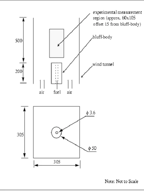
The bluff-body burner is centred in a co-flowing stream of air and consists of a circular bluff-body with an orifice at its centre for the fuel. Fig.1 shows a schematic of the experimental setup.
Figure 1: Schematic of the Masri Bluff body burner. (in mm)
The bluff body is of 50mm diameter and the orifice is of 3.6mm diameter. Experimental measurements were taken in a region 60mm by 105mm downstream of the bluff-body. The fuel used is a 1:1 (by volume) mixture of methane and hydrogen, while the co-flowing oxidant is air. The fuel jet has an inlet velocity of 118m/s and the oxidant of 40m/s.
The experiment provides measurements of mass fractions of methane (CH4), carbon monoxide (CO),
carbon dioxide (CO2), hydrogen (H2), water vapour
(H2O), hydroxyl radical (OH), nitrogen (N2) and oxygen
(O2).
B. CFD Modelling Approach
i. Geometry and Computational Mesh
The computational domain extended 100mm upstream of the bluff body face, and 500mm downstream. The orifice itself was not included. A 45 degree wedge of the wind tunnel was modelled. Three computational meshes with cyclic boundaries with 40k, 120k and 200k cells respectively, were generated by extruding a two-dimensional surface along the length of the tunnel. The three meshes were developed for a grid dependence study, and in each case the mesh resolution is concentrated in the experimental measurement region and burner surface using zonal refinement. All cells are hexahedral in shape apart from a set of prism cells along the grid centreline.
ii. Boundary Conditions
The orifice itself was not modelled and a velocity profile with a mean value of 118m/s based on the test data was applied at the fuel inlet. The inlet velocity of the co-flowing air is 40m/s. The air is assumed to consist of 23.3% (by mass) oxygen and 76.7% nitrogen only. The fuel consists of 88.8% (by mass) methane and 11.2% hydrogen. The inlet temperature of both fuel and oxidant streams was specified as 298ºK. Inlet turbulence parameters are specified as a turbulent intensity and length scale.
iii. Thermofluids Considerations
The flow was assumed to be steady, three dimensional, compressible and fully turbulent. Transport equations were solved for the three momentum components, mass continuity, temperature, turbulence and the appropriate combustion scalars for each combustion model.
Turbulence was accounted for using High-Reynolds number formulations of the standard k-ε, Chen k-ε, RNG k-ε and the quadratic and cubic k-ε two equation turbulence models. Y+ values on wall surfaces were between 50 and 100, appropriate to the wall functions being used. The wall surfaces are all set to be adiabatic.
• Density: using the ideal gas law. • Molecular viscosity: 1.81x10⁻⁵ kg/ms
• Specific heat: calculated from polynomial functions in the Chemkin database.
The experiment was conducted with hydrogen as part of the fuel to minimise the soot content, and the radiative heat transfer effects are therefore negligible and ignored in the CFD models. The chemico-thermal form of the enthalpy equation is used when required. The specification of the chemistry models is discussed in the next section.
iv. Chemistry Modelling
Four combustion models are applied in this work. They are the EBU, the Adiabatic and the Non-adiabatic PPDF, and the Laminar Flamelet models respectively. Details of the EBU and PPDF models methodology can be obtained in [2]. The Laminar Flamelet model is a new feature developed in CFD package and details of the model can be found in [2]. The setup of each model is now discussed in the following subsections.
1. The Eddy Break-up Model
In this application the following reactions, which are assumed single step and irreversible, were specified for the EBU model:
CH4 +0.5O2 → 2H2 + CO
H2 + 0.5O2 → H2O
CO + 0.5O2 → CO2
Ignition is initiated between iteration 50 and 150 with 5% fraction of fuel burned. The default CFD empirical reaction coefficients as follows were used:
A ebu = 4.0
B ebu = 0.5
2. The Presumed Probability Density Function schemes
Both the adiabatic and non-adiabatic versions of the Presumed pdf scheme are used in this work. In each case the following species are included, CH4, O2, N2,
CO, CO2, H2, H2O and OH. In the adiabatic version, no
enthalpy equation is solved.
3. The Laminar Flamelet Model
Two Laminar Flamelet libraries were set up for this case, labelled Version 1 and Version 2 as follows:
In Version 1 eighteen species were used to generate four libraries at strain rates of 21s-1, 46s-1, 180s-1 and 377s-1.
In version 2 twenty seven species were used to generate six libraries at strain rates of 18s-1, 22s-1, 46s-1, 106s-1, 316s-1 and 976s-1. Version 2 included species involving reactions with Nitrogen, e.g. NO, NO2 and HCN, as
well as all the species included in version 1. The enthalpy equation is not solved for the Laminar Flamelet simulations.
III. RESULTS AND DISCUSSION
A. Numerical and Computational Considerations
The second-order discretisation scheme was used for the momentum and energy equations. Upwind differencing was used for the turbulence parameters and central differencing for density. In order to obtain convergence the under-relaxation factors were reduced as follows:
• for momentum from .7 to .5 • for pressure from .3 to .2
• for temperature and combustion scalars from .95 to .7
• for the turbulence parameters from .7 to .5.
The residual tolerance was reduced to .001 for the temperature and active scalar parameters to ensure they remained coupled. All calculations were undertaken using double precision.
A typical calculation on the 200,000 cell mesh took 100 hours to do 20,000 iterations on a single Pentium 1Ghz PC using 195MB of memory. A 40,000 cell mesh calculation for the same case required 6,000 iterations, 18 hours of CPU time and 48Mb of memory to obtain a converged solution.
B. CFD Simulation Results & Conclusions
front of the burner face, which was comparable to the measurements. The results of the computational model are compared with the experimental data (figure 2&3).
Figure 2: Carbon monoxide CO mass concentration for the EBU model
Figure 3: Carbon dioxide CO2 mass concentration for
the EBU model
Further, the species mass fractions and temperature were investigated. Good agreement was achieved with the EBU model with most of the Masri experimental data by using the Chen K-epsilon turbulence model. However, very poor predictions of the CO and CO2
concentrations were obtained. In order to address this
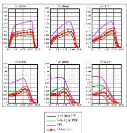
we considered the PPDF and Laminar flamelet approach. The results from the PPDF model indicated CO concentrations levels much higher than the EBU model, while CO2 predictions are much better than EBU results
(figure 4&5).
Figure 4: Carbon monoxide CO predictions for PPDF model versus test data.
Figure 5: Carbon dioxide CO2 predictions for PPDF
model versus test data.
The H2 and H2O concentrations and temperature are not
all reactions reach chemical equilibrium based on algebraic relations.
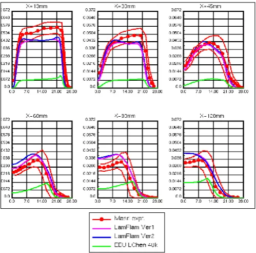
Two simulations with laminar flamelet model were undertaken using the Chen K-epsilon turbulence model. The predictions of CO and CO2 are much better than the
EBU reflecting the higher fidelity of the physics involved in the flamelet model (figure 6&7).
Figure 6 : Carbon monoxide CO predictions for Laminar flamelet model versus test data.
Figure 7 : Carbon dioxide CO2 predictions for Laminar
flamelet model versus test data.
The temperature profiles also improved compared to EBU model. The predictions of the species mass fractions and the shape of the peaks is excellent showing that the flamelet approach is predicting the combustion mechanism well.
It is recommended to examine the configuration studied in this paper using Large Eddy simulation (or Direct Eddy simulation) in combination with each of the studied combustion models: EBU, PPDF and Laminar Flamelet. Further test data cases are available from the Masri project. These include two further cases with this geometry but with different fuel and co-flow velocities.
IV. CONCLUSION
By using this proposed model a secured path can be established for communication. The system provides security at different point in time starting from cluster head election (SLEACH), secure data transfer through session establishment CKM with inclusion of pair wise key establishment (RCD and RMCM) in case of intra-cluster communication and triple key establishment in case of inter-cluster communication and watchdog nodes with rules definition and KDD data set. Hence, as a system it provides different layer of security and monitoring. Certain rules for internal attackers have been defined in the model. The KDD dataset have been used as a protective measure in the model. The KDD dataset can be well trained and implemented in the future so that a better secured system can be implemented. Also with respect to key distribution and establishment randomized combinatorial design theory and markov chain model has been used. RMCM is surely grant security in terms of key distribution but further improvements can be made on successful key generation rate.
V.
REFERENCES
[1] B B Dally, D F Fletcher and A R Masri. 1998. Combustion Theory Modelling 2 (1998) pg.193– 219, 1998. “Flow and mixing fields of turbulent
bluff-body jets and flames”.
http://www.mech.eng.usyd.edu.au/research/energy/r esources.html