O R I G I N A L A R T I C L E
Open Access
Slicing and support structure generation for
3D printing directly on B-rep models
Kanle Shi
1,2,3, Conghui Cai
1,2,3, Zijian Wu
1,2,3and Junhai Yong
1,2,3*Abstract
Traditional 3D printing is based on stereolithography or standard tessellation language models, which contain many redundant data and have low precision. This paper proposes a slicing and support structure generation algorithm for 3D printing directly on boundary representation (B-rep) models. First, surface slicing is performed by efficiently computing the intersection curves between the faces of the B-rep models and each slicing plane. Then, the normals of the B-rep models are used to detect where the support structures should be located and the support structures are generated. Experimental results show the efficiency and stability of our algorithm.
Keywords:3D printing, Boundary representation model, Slicing, Support structure generation, Intersection curve
Background
Recently, 3D printing has been widely used. However, printing quality and speed issues of 3D printing remain unsolved.
Slicing is a foundational operation of 3D printing. It requires computing the intersection curves of models and slicing planes. This operation is time-consuming, and is a key factor that affects printing quality.
Most slicing algorithms work on standard tessellation language (STL) models [1–4], as STL is a standard file format for 3D printing. However, the data in the STL file format is a discretized form of the 3D models, which contain discretization errors. Thus, many studies consid-ered a slicing algorithm on the original data of the 3D models.
Chen et al. [5] used the AutoSection toolkits provided by PowerSHAPE to directly slice computer aided design
(CAD) models. Cao and Miyamoto [6] implemented
sli-cing on the entity models in AutoCAD. Starly et al. [7] performed slicing operations directly on non-uniform rational basis spline models in the standard for the ex-change of product model data format. Pandey et al. [8] proposed a slicing procedure for fused deposition mod-elling (FDM), based on a real-time edge profile of depos-ited layers.
Support structure generation is another foundational operation of 3D printing. It affects printing quality and material consumption. If the necessary support struc-tures are missed, then 3D printing will fail. In addition, unnecessary support structures mean more required ma-terials and more printing time.
Alexander et al. [9] proposed a method for support
generation based on the orientation and size of the patch in the STL model. This method is adopted by several commercial 3D printers, but the support structures that it generates can be reduced, practically.
Some research [10–14] aimed to produce better struc-tures to reduce the quantity of support structure. Wang et al. [11] proposed a support structure consisting of some thin rods. These thin rods are from different directions as compared to a simple vertical direction [9], with much fewer support structures. Chen et al. [5,15] presented an optimized thin rod structure. The optimized structure has better printability and stability. The thin rods are easier to remove from the surface. Vanek et al. [13] proposed an algorithm to generate a tree-like support structure. This algorithm used thin rods to form a tree-like structure, which is more stable. Dumas et al. [12] presented a scaf-folding support structure. This structure has better sup-port strength and stability than the tree-like structure.
The contributions of our study are a slicing algorithm for boundary representation (B-rep) models and a support structure generation algorithm. The slicing algorithm is directly based on B-rep models that reduce the
© The Author(s). 2019Open AccessThis article is distributed under the terms of the Creative Commons Attribution 4.0 International License (http://creativecommons.org/licenses/by/4.0/), which permits unrestricted use, distribution, and reproduction in any medium, provided you give appropriate credit to the original author(s) and the source, provide a link to the Creative Commons license, and indicate if changes were made.
* Correspondence:[email protected]
1School of Software, Tsinghua University, Beijing, China
2Beijing National Research Center for Information Science and Technology,
Beijing, China
The remaining parts of this paper are arranged as follows. Section 2 briefly introduces the framework of the algorithm, then it presents the detail of model sli-cing and support structure generation separately. The experimental results are presented in Section 3. Sec-tion 4 provides conclusions for the study.
Methods
Overview
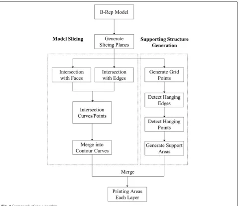
Model slicing and support structure generation are two key steps in 3D printing. The framework of our slicing
tion points between the edges of the B-rep model and each slicing plane. These intersection points are used to split the intersection curves into several seg-ments, where the intersection curves only intersect each other, at most, at endpoints. Thus, the intersec-tion points become endpoints of the intersecintersec-tion curves. Lastly, we analyze the intersection curves to obtain a contour curve of the B-rep model on each slicing plane.
For support structure generation, we compute the grid points of the B-rep model. With the normals of
the grid points we compute the supporting region inside, in which hanging points and edges are also detected, to obtain supporting areas for each slicing layer. Lastly, we generate support structures for 3D printing.
Model slicing
Our slicing operations work directly on B-rep models. The workflow is as follows.
Generate slicing planes
We compute the height of the B-rep model along the slicing direction. We generate the slicing planes ac-cording to the distance between two neighbor slicing layers.
Calculate intersections
We compute the intersection curves between each face in the B-rep model and each slicing plane, as well as the intersection points between each edge in the B-rep model and each slicing plane.
Generate contour curve for each layer
We analyze the intersection curves to obtain a contour curve of the B-rep model on each slicing plane.
Generate slicing planes
The slicing direction is perpendicular to the slicing planes. We rotate the B-rep model for the Z axis to be in the slicing direction. Then, we calculate the height of the B-rep model along the Z axis. The number of slicing planes is the height of the B-rep
model divided by the distance between the two neigh-bor slicing planes. We set the Z-coordinate of the lowest point of the B-rep model to be 0. All the equations representing slicing planes are obtained as follows:
Z¼i dsp;
where dsp is the distance between the two neighbor
sli-cing planes, i= 0, 1, …, bhB
dspc, hB is the height of the
B-rep model along the Z axis, and ⌊∙⌋is the floor func-tion, which produces the greatest integer less than the
given number. Here, dspis given by the user before 3D
printing.
Calculate intersections
In model slicing, the most difficult step is computing the intersection results between faces or edges of the B-rep model and each slicing plane. In the B-rep model, faces are usually made by trimmed surfaces. Therefore, computing the intersection curves between a face in the B-rep model and a slicing plane can be divided into two steps. First, the intersection curves
Cis are computed between the untrimmed surface of
the face and the slicing plane. Second, the
intersec-tion curves Cis are cut by the boundary of the face.
To speed up computing the intersection curves Cis
between the untrimmed surface and the slicing plane, we develop several intersection functions, each of which works on a type of surface, such as a plane, sphere, ellipsoid, cylinder, elliptical cylinder, cone, and
elliptical cone. The resultant intersection curves
Fig. 2Intersection results depend on directions of surfaces and slicing planes
depend on the directions of surfaces and slicing planes, as illustrated in Fig. 2. The intersection curves
Cis are directly discretized during the process of
intersection, and thus are converted into a set of polylines {Pi | Pi= {p1, p2, …, pn}}, where Pi is a
poly-line, pk (k= 1, 2, …, n) is a discrete point, and n is
the number of discrete points in the polyline Pi.
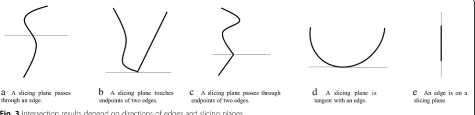
Computing the intersection results is a difficult task. Numerous cases exist, and these cases should be
considered separately. Figure 3 depicts some cases of
computing intersection points between the edges of the B-rep model and slicing planes. The results de-pend on the directions of edges and slicing planes.
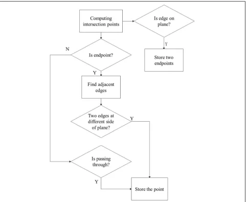
The flowchart for computing intersection points between the edges of the B-rep model and a slicing
plane is presented in Fig. 4. First, we determine
whether an endpoint of the edge is an intersection point. Thus, we find two adjacent edges of the point. If the two adjacent edges are on the same side of
the slicing plane (Fig. 3b, then we abandon the
inter-section point. If the two adjacent edges are on
dif-ferent sides of the slicing plane (Fig. 3c), then we
store the intersection point. If the intersection point is on an edge but is not the endpoint of the edge, then the intersection point divides the edge into two segments. If the two segments are on the same side
of the slicing plane (Fig. 3d), then we abandon the
intersection point. If the two segments are on differ-ent sides of the slicing plane (Fig. 3a), then we store the intersection point. If the edge is on the slicing
plane (Fig. 3e), then we store two endpoints of the
edge.
Generate contour curve
Before generating contour curves, we use the inter-section points between the edges and each slicing plane to split the intersection curves between the faces and each slicing plane into several segments,
such that each intersection curve segment intersects each other segment, at most, at endpoints. An intersection point should be at least on an intersection curve because an edge should be on a face. Thus, the splitting can be performed. We then connect the intersection curve seg-ments of the splitting results to form loops, which are the contour curves on the B-rep model and the slicing planes.
Support structure generation
For fused-deposition 3D printing, support structure gener-ation is necessary for hanging parts of models. Otherwise,
3D printing may fail because of gravity. Our support structure generation can be performed automatically. The workflow is as follows.
Generate Grid Points: Grid points are sampled directly on the B-rep models, and the normals, height, and sup-port type information are stored.
Detect Hanging Edges/Points: Hanging edges and points that may be missing during sampling are detected.
Generate Supporting Areas: Supporting areas are generated according to the results of the above two steps.
Supporting types
In our support structure generation, supporting is classi-fied into the following three types.
None: Indicates that the grid point has no specific supporting type.
ForceSupport: Indicates that the grid point is a forced supporting point.
ForceNoSupport: Indicates that no support can be imposed on the grid point.
The three supporting types can be manually set on some grid points. As support structures may make touch points on models less smooth, it is necessary to manu-ally set the supporting types on some grid points, so as to guarantee the quality of some parts of models.
Generate grid points
We create points evenly along the X-axis and Y-axis. Then, we project these points on the B-rep models along the Z-axis to generate the grid points on the B-rep models. These grid points are also the sample points on the B-rep models. We calculate the normals and the height values at the grid points, and store the support types at the grid points.
Detect hanging edges and points
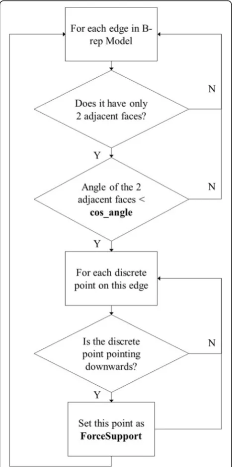
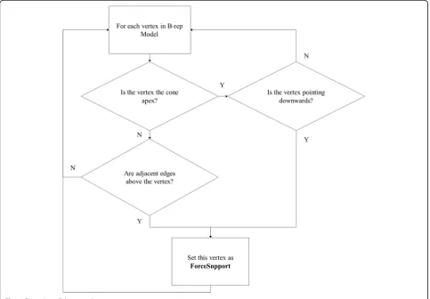
Given that edges and vertices are crucial on the B-rep models, they must also be detected. If we find that edges or vertices on the B-rep models are hang-ing, then we will set them with the supporting type ForceSupport. The edges that are hanging are called hanging edges, and the vertices that are hanging are called hanging points. The flowcharts for detecting
hanging edges and points are presented in Figs. 5
and 6, respectively.
As shown in Fig. 5, we judge whether an edge has 2
adjacent faces. If the edge has 2 adjacent faces, we judge whether the angle of these adjacent faces is smaller than
a threshold cos_angle. Then, we discretize the edge and judge whether the discrete point is pointing downwards. We calculate the angle between the normal of the discrete point and the vector (0, 0, −1). If the angle is
smaller than cos_angle, we consider the point as
point-ing downwards, and mark the point as ForceSupport.
The value ofcos_angleisπ/3.
As shown in Fig. 6, there are two kinds of vertices
which are hanging points. The first one is the cone apex. If the vertex is the cone apex and the vertex is pointing
downwards, we mark this vertex as ForceSupport. The
algorithm for determining whether the vertex is pointing downwards is described above. The second kind of ver-tex, which is a hanging point, is a vertex in which all of its adjacent edges are above it. We calculate all the end-points of its adjacent edges, and if the z values of these endpoints are not smaller than the z value of the vertex,
we mark the vertex asForceSupport.
Generate supporting areas
We add all grid points with the supporting type ForceSupport, hanging edges, and hanging points into the supporting areas. We calculate the angles
between the normals of grid points with the
support-ing type None and the X-axis. If angles are greater
than a threshold, then the grid points are added to the supporting areas. Lastly, we remove all the grid
points with the supporting type ForceNoSupport
from the supporting areas. Support structures are
generated after the final supporting areas are
obtained.
Results
We conducted numerous experiments to test our sli-cing and support structure generation algorithm.
This section shows some typical experimental
results.
Model slicing
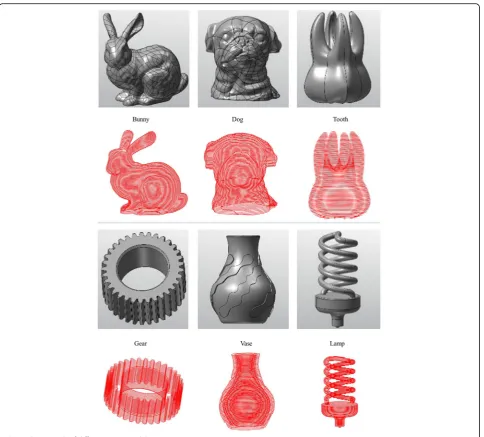
The experimental results of the six models are
pre-sented in Fig. 7 and Table 1. As shown in Fig. 7, the
gray models are six B-rep models, and the red sliced models are the slice results of the respective B-rep models above them by our model slicing algorithm.
Table 1 shows the face and slice numbers of these six
models. The third column in the table shows that
these B-rep models have different face types. It proves that our model slicing algorithm can handle different face types in different B-rep models.
The experimental results of the six models are
pre-sented in Fig. 7 and Table 2. We compare our
algo-rithm with the algoalgo-rithms in Slic3r [16] and Cura
[15]. Our algorithm works directly on the B-rep
models, whereas Slic3r and Cura work on STL models converted from the same B-rep models. For a fair comparison, we require the same 3D printing precision, which is 0.1 mm, and the same number of
layers. According to Table 2, our algorithm consumes
considerably less time than Slic3r and Cura.
Support structure generation
In this study, the support generation algorithm gener-ates the support of the model hanging edge and the suspension point. One way to accomplish this is to automatically generate the corresponding support at the bottom of the suspension edge and the suspen-sion point by detecting the suspensuspen-sion edge and the suspension point. In this study, we first used the Repetier-Host software to visualize the model support generation. The support generation algorithm in this
study is shown in Fig. 8. The left and right in Fig. 8
are the hanging edge and point examples with the support generation results of Slic3r, Cura, and our
support generation algorithm, respectively. Slic3r is generated by default support, and the Cura support
generated suspension angle is set to π/3, the same as
with our detecting algorithm. The support area fill types are both set to a straight-line fill. As shown in Fig. 8, Slic3r can detect a hanging edge well, but can-not handle a hanging point well. The support gener-ated by Slic3r for the hanging point example is very redundant. Cure can detect a hanging point well, but cannot detect a hanging edge. Our algorithm can detect both the hanging edge and the hanging point
in the model, and the support structures are
well-generated, with almost no redundancy.
The examples shown in Fig. 8 prove that our
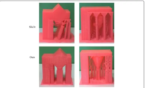
algo-rithm can generate support structures well for hang-ing edges and points. After the step of support
generation, we print the two examples in Fig. 8 with
Slic3r and with our algorithms, respectively. The comparison of print results with our algorithm and
the Slic3r is shown in Fig. 9. For the two examples, the support structures generated by Slic3r cannot
support 3D printing well. Some parts of the models fail to be printed. By comparison, our algorithm can work well on the two examples. The triangle and the cone in the middle of the models are well-printed.
Discussion and conclusion
This paper proposes a slicing and support structure generation algorithm that can work directly on B-rep models. The experimental results show that our algo-rithm can improve the efficiency and stability of 3D printing. Our algorithm also allows users to specify
Fig. 8Examples of supporting structure generation with different methods
Table 2Time cost of different algorithm
Model Time
Ours Slic3r Cura
Finger Plate 0.037 s 5.239 s 0.124 s
Wristband 0.180 s 15.323 s 0.484 s
Christmas tree 0.020 s 1.958 s 0.031 s
Cup 0.128 s 14.044 s 0.671 s
Pen Holder 0.271 s 35.633 s 1.607 s
Bowl 0.022 s 1.893 s 0.047 s
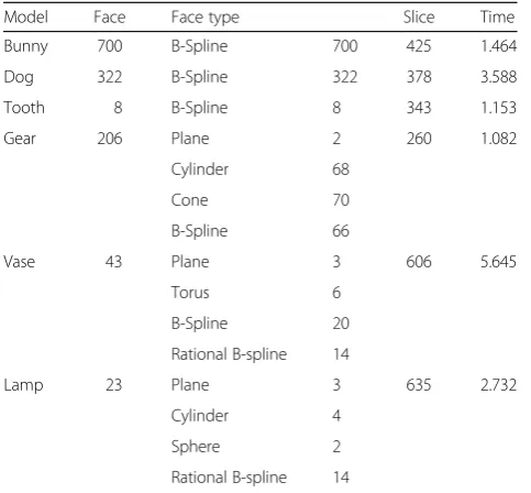
Gear 206 Plane 2 260 1.082
Cylinder 68
Cone 70
B-Spline 66
Vase 43 Plane 3 606 5.645
Torus 6
B-Spline 20
Rational B-spline 14
Lamp 23 Plane 3 635 2.732
Cylinder 4
Sphere 2
the supporting types, thus increasing the flexibility of 3D printing.
In the future, we will continue to improve the effi-ciency of 3D printing. We will attempt to find some new ways of reducing the cost of support structures while retaining the stability.
Abbreviations
B-Rep:Boundary representation; CAD: Computer aided design; FDM: Fused deposition modelling; NURBS: Non-Uniform Rational B-Splines;
STEP: Standard for the exchange of product model data; STL: Stereo lithography
Funding
This work is was funded by National Natural Science Foundation of China under Grant No. 61672307.
Availability of data and materials
The datasets used or analysed during the current study are available from the corresponding author on reasonable request.
Authors’contributions
All authors wrote, read and approved the final manuscript.
Authors’information
Kanle Shi is currently an assistant professor in School of Software at Tsinghua University. His research interests include 3D printing, CAD and computer graphics.
Conghui Cai is currently a master candidate in School of Software at Tsinghua University. His research interests include CAD and computer graphics.
Zijian Wu is currently an engineer in School of Software at Tsinghua University. His research interests are CAD and computer graphics.
Junhai Yong is a professor in School of Software at Tsinghua University. His main research interests include CAD and computer graphics.
Competing interests
No conflict of interest exits in the submission of this manuscript, and manuscript is approved by all authors for publication. I would like to declare on behalf of my co-authors that the work described was original research that has not been published previously, and not under consideration for publication elsewhere, in whole or in part. All the authors listed have ap-proved the manuscript that is enclosed.
Publisher’s Note
Springer Nature remains neutral with regard to jurisdictional claims in published maps and institutional affiliations.
Author details
1School of Software, Tsinghua University, Beijing, China.2Beijing National
Research Center for Information Science and Technology, Beijing, China.3Key
Laboratory for Information System Security, Ministry of Education of China, Beijing, China.
Received: 17 December 2018 Accepted: 14 April 2019
References
1. Sabourin E, Houser SA, Bøhn JH (1996) Adaptive slicing using stepwise uniform refinement. Rapid Prototyp J 2(4):20–26.https://doi.org/10.1108/ 13552549610153370
2. Tyberg J, Bøhn JH (1998) Local adaptive slicing. Rapid Prototyp J 4(3):118–127.
https://doi.org/10.1108/13552549810222993
3. Cormier D, Unnanon K, Sanii E (2000) Specifying non‐uniform cusp heights as a potential aid for adaptive slicing. Rapid Prototyp J 6(3):204–212.https:// doi.org/10.1108/13552540010337074
4. Alexa M, Hildebrand K, Lefebvre S (2017) Optimal discrete slicing. ACM Trans Graph 36(1):12.https://doi.org/10.1145/3072959.3126803
387–397.https://doi.org/10.1016/j.cad.2004.06.014
8. Pandey PM, Reddy NV, Dhande SG (2003) Real time adaptive slicing for fused deposition modelling. Int J Mach Tools Manuf 43(1):61–71.https://doi. org/10.1016/S0890-6955(02)00164-5
9. Alexander P, Allen S, Dutta D (1998) Part orientation and build cost determination in layered manufacturing. Comput Aided Des 30(5):343–356.
https://doi.org/10.1016/S0010-4485(97)00083-3
10. Huang XM, Ye CS, Wu SY, Guo KB, Mo JH (2009) Sloping wall structure support generation for fused deposition modeling. Int J Adv Manuf Technol 42(11–12):1074–1081.https://doi.org/10.1007/s00170-008-1675-2
11. Wang WM, Wang TY, Yang ZW, Liu LG, Tong X, Tong WH, et al (2013) Cost-effective printing of 3D objects with skin-frame structures. ACM Trans Graph 32(6):177.https://doi.org/10.1145/2508363.2508382
12. Dumas J, Hergel J, Lefebvre S (2014) Bridging the gap: automated steady scaffoldings for 3D printing. ACM Trans Graph 33(4):98.https://doi.org/10. 1145/2601097.2601153
13. Vanek J, Galicia JAG, Benes B (2014) Clever support: efficient support structure generation for digital fabrication. Comput Graph Forum 33(5):117–125.https:// doi.org/10.1111/cgf.12437
14. Chen Y, Wang SW, Yang ZW, Liu LG (2015) Construction of support structure for FDM 3D printers. Sci Sin Informationis 45(2):259–269. 15. Slic3r - open source 3D printing toolbox.http://www.slic3r.org. Accessed 20
Oct 2018.