Research Forum
Stress-strain in anisotropic solid medium
S.S. Singh* and Malsawmsangi Varte
Department of Mathematics and Computer Science, Mizoram University, Aizawl 796 004, India
Received 13 June 2012 | Revised 19 July 2012 | Accepted 13 August 2012
ABSTRACT
The numbers of elastic constants in the anisotropic medium has been investigated through the Car-tesian co-ordinate plane symmetry. We have observed different types of anisotropic medium have different number of elastic constants. These constants are related with the properties of the me-dium.
Key words: Anisotropic medium; monoclinic medium; orthotropic medium; transversely iso-tropic medium; isoiso-tropic medium.
Corresponding author: Sarat Singh
Phone: +91-9863274645 Fax : 0389-2315212 E-mail: [email protected]
INTRODUCTION
A uniform material which contains an in-ternal structure (such as crystal), so that elas-tic properties vary with direction, is defined as anisotropic elastic medium. The variation of properties for purely elastic solids containing crystals can be fully described by a fourth-order tensor of anisotropic elastic constants. Theoretical seismology aims to study earth-quake phenomenon with the application of mathematical methods. Earthquakes and other disturbances generate seismic waves, which give information about both the source and the material they pass through. An earth-quake is the result of release of energy some-where inside the earth. This released energy sets up various types of elastic waves which are transmitted in the earth with definite
ve-locities depending on the density and the elas-tic parameters of the materials in the earth.1
Seismologists observed that the seismic waves propagated by sedimentary rocks do not always behave as if the medium were iso-tropic. The property of velocity anisotropy, hereafter referred to, simply as anisotropy, is characterized by the variations of velocity with the direction of propagation. Many re-searchers investigated the problem of anisot-ropic elastic medium. Song and Helmberger2
investigated the problem of anisotropy of Earth’s inner core. They explained the differ-ent forms of anisotropy in the earth’s inner core. Musgrave3 showed the theoretically and
numerically that there are fundamental differ-ences between the propagation of seismic waves in isotropic and anisotropic media. These differences are subtle and difficult to detect on observed seismograms. Crampin4
observed that the calculation of synthetic seis-mograms is an important technique for deter-Sci Vis 12 (3), 117-124
mining the effects of anisotropy on seismic wave propagation in any particular earth’s structure. Singh5 studied the quasi nature of
elastic waves in the anisotropic medium. He had shown that the quasi nature of elastic waves is due to the phase velocity of elastic waves in the anisotropic medium depending on the angle of propagation of the medium. Auld6 studied the problems of acoustic fields
and waves in solids. Malvern7 attempted the
problem on the introduction to the mechanics of a continuous medium.
In this work, the fundamental of anisot-ropic medium has been discussed. We have observed that different types of anisotropic medium have different number of elastic con-stants to represent the stress–strain relation-ship. We study the generalized anisotropic medium, monoclinic medium, orthotropic medium, hexagonal symmetry, transversely isotropic medium, cubic medium and iso-tropic medium which are having different number of elastic constants.
HOOKE’S LAW
The generalized Hooke’s Law says that for sufficiently small strains, each component of stress tensor is a linear combination of the components of strain tensor. The coefficients in the linear form connecting the components of these tensors are elastic constants. In the generalized Hooke’s Law, there are thirty six elastic constants and is given as
ℑij = Cijklekl, (i, j, k, l = 1, 2, 3); Cijkl = Cjikl
= Cijlk 2.1
Let us introduced the following notations to avoid dealing with double sums
ℑ1 = ℑ11 ℑ2 = ℑ22 ℑ3 = ℑ33
ℑ4 = ℑ23 ℑ5 = ℑ31 ℑ6 = ℑ12 2.2
e1 = e11 e2 = e22 e3 = e33
e4 = 2e23 e5 = 2e31 e6 = 2e12 2.3
Equation (2.1) may be re-written as ℑi = Cijej (i, j = 1, 2, .., 6) 2.4
which may be represented the following ma-trix as
2.5 Or in terms of co-ordinates
where ℑxx = ℑ1 ℑyy = ℑ2 ℑzz = ℑ3
ℑyz = ℑ4 ℑzx = ℑ5 ℑxy = ℑ6
exx = e1 eyy = e2 ezz = e3
2eyz = e4 2ezx = e5 2exy = e6
The maximum number of elastic constants is thirty six in this case.
The strain energy density function (W) of the anisotropic medium is defined by
W = Cijeiej 2.6
with the property that
= ℑi ; (i= 1, 2, 3) 2.7
Differentiating Equation (2.4) with respect to ek, we get
2.8
(Because j is dummy suffix)
By Equations (2.4) and (2.7), we have ℑk = Ckiei
and = Ckiei
With the help of Equation (2.8)
Cki ej + Cik ei = Ckiei, which implies that
Cki = Cik or Cij = Cji (i, j = 1, 2, 3), i.e., Cij
𝜕𝑊 𝜕𝑒𝑘 =
1 2 Cij (
𝜕𝑒𝑖 𝜕𝑒𝑘𝑒𝑗 + 𝑒𝑖
𝜕𝑒𝑗 𝜕𝑒𝑘)
=12 Cij (δike j +eiδjk)
=12 Cki ei +
is symmetric.
This makes 21 elastic constants. Thus twenty-one independent elastic constants form a general anisotropic body. If any me-dium is elastically symmetric in certain direc-tion, then the number of independent con-stants may be less than 21.
STRESS AND STRAIN UNDER THE
TRANS-FORMED OF AXIS
Let us transform the coordinate axis from (X, Y, Z) to (X′ , Y′ , Z′ ) with the follow-ing direction cosines given by
In the new transformed coordinate system, the generalized Hooke’s Law is given as
; (i, j = 1, 2, …., 6) 3.1 The new stress traction may be written as ; (α, β, i, j = 1, 2, 3) 3.2 Thus = l1il1jℑij ; (i, j = 1, 2, 3)
= l11l11ℑ11+l11l12ℑ12+l11l13ℑ13+l12l11ℑ21+
l12l12ℑ22+l12l13ℑ23+l13l11ℑ31+l13l12ℑ32+l13l13ℑ33
3.2a
ℑ′22= l2il2jℑij ; (i, j = 1, 2, 3)
= l21l21ℑ11+l21l22ℑ12+l21l23ℑ13+l22l21ℑ21
+l22l22ℑ22+l22l23ℑ23+l23l21ℑ31+l23l22ℑ32
+l23l23ℑ33 3.2b
ℑ′33=l3il3jℑij ; (i, j = 1, 2, 3)
= l31l31ℑ11+l31l32ℑ12+l32l31ℑ21+l32l32ℑ22+
l32l32 ℑ22 +l32l33ℑ23+l33l31ℑ31+l33l32ℑ32
+l33l33ℑ33 3.2c
ℑ′23 =l2il3jℑij ; (i, j = 1, 2, 3)
=l21l31ℑ11+l21l32ℑ12+l21l33ℑ13+l22l31ℑ21+
l22l32 ℑ22 +l22l33ℑ23+l23l31ℑ31+l23l32ℑ32
+l23l33ℑ33 3.2d
ℑ′31 =l3il1jℑij ; (i, j = 1, 2, 3)
=l31l11ℑ11+l31l12ℑ12+l31l13ℑ13+l32l11ℑ21+l3 2l12 ℑ22 +l32l13ℑ23+l33l11ℑ31+l33l12ℑ32+
l33l13ℑ33 3.2e
ℑ′12=l1il2jℑij ; (i, j = 1, 2, 3)
=l11l21ℑ11+l11l22ℑ12+l11l23ℑ13+l12l21ℑ21+l1 2l22 ℑ22+l12l23 ℑ23+l13l21ℑ31+l13l12ℑ32+l13l13ℑ33
3.2f The new strain components may be writ-ten as
e′αβ= lαilβjeij ; (α, β, i, j = 1, 2, 3) 3.3
Thus e′11 = l11l11e11+l11l12e12+l11l13e13+l12l11e21
+l12l12 e22 +l12l13e23+l13l11e31+l13l12e32
+l13l13e33 3.3a
e′22 = l21l21e11+l21l22e12+l21l23e13+l22l21e21
+l22l22 e22+l22l23e23+l23l21e31+l23l22e32+l23l23e33
3.3b
e′33 = l31l31e11+l31l32e12+l32l31e21+l32l32e22
+l32I32 e22+l32l33e23+l33l31e31+l33l32e32+l33l33e33
3.3c
e′23 = l21l31e11+l21l32e12+l21l33e13+l22l31e21
+l22l31 e21+l22l32e22+l22l33e23+l23l32e32+l23l33e33
3.3d
e′31 = l31l11e11+l31l12e12+l31l13e13+l32l11e21
+l32l12 e22+l32l13e23+l33l11e31+l33l12e32+l33l13e33
3.3e
e′12 = l11l21ℑ11+l11l22e12+l11l23e13+l12l21e21
+l12l22 e22+l12l23 e23+l13l21e31+l13l12e32
+l13l13e33 3.3f
Thus, we have seen that there are different values of stress tensors and strain tensors for the new co-ordinate systems. This makes us possible to find the different numbers of elas-tic constants for different elaselas-tic plane sym-metry.
MEDIUM WITH ONE PLANE OF ELASTIC SYMMETRY
A substance is considered elastically sym-metric with respect to XY-plane (or Z-plane). Under this symmetry, the elastic constants are invariant in the transformation
X = X’,Y and Z = -Z’
X Y Z
X’ l11 l12 l13
Y’ l21 l22 l23
The direction cosines for this transforma-tion are given as
With the help of Equations (3.2a-f) and (3.3a-f), we have
ℑ′1= ℑ1 ℑ′2= ℑ2 ℑ′3= ℑ3
ℑ′4= -ℑ4 ℑ′5 = -ℑ5 ℑ′6= ℑ6 4.1
and e′1 = e1 e′2 = e2 e′3 = e3
e′4 = -e4 e′5 = -e5 e′6 = e6 4.2
Using Equations (4), (10), (13) and (14), we get
ℑ1 =ℑ′1
or C11e1 + C12e2 + C13e3 + C14e4 + C15e5 +
C16e6
= C11e′1 + C12e′2 + C13e′3 + C14e′4 + C15e′5
+ C16e′6
or C11e1 + C12e2 + C13e3 + C14e4 + C15e5 +
C16e6
= C11e1 + C12e2 + C13e3 - C14e4 - C15e5 +
C16e6
or C14e4 + C15e5 = -C14e4 – C15e5
Comparing the coefficients of e4 and e5, we
have
C14 = -C14 and C15 = -C15 which implies C14
= 0 and C15 = 0.
Similarly, ℑ′2 = ℑ2 gives C24 = 0 and C25 =
0;
ℑ′3 = ℑ3 gives C34 = 0 and C35 = 0;
ℑ′4= -ℑ4 gives C41 = C42 = C43 = C46 = 0;
ℑ′5= -ℑ5 gives C51 = C52 = C53 = C56 = 0;
ℑ′6= ℑ6 gives C64 = C65 = 0.
The system of Equation (2.5) may be re-written as
4.3 There are only thirteen elastic constants. A medium in which the elastic system is repre-sented by thirteen elastic constants is known as anisotropic medium with monoclinic sym-metry or monoclinic medium.
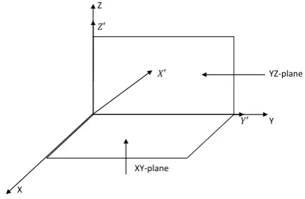
MEDIUM WITH TWO PLANE OF ELASTIC SYMMETRY
A medium of two plane elastic symmetry is generally denoted as orthotropic medium. In such a case, we choose the axis of the co-ordinates so that the co-ordinate planes coin-cide with the planes of elastic symmetry as shown in Figure 2.
Z
O 𝑌’ Y
. P (X, Y, -Z)
𝑿’
X 𝑍’
Figure 1. Reflection symmetry across XY-plane.
X Y Z
X’ 1 0 0
Y’ 0 1 0
Z’ 0 0 -1
Z
𝑍′
𝑋′ YZ-plane
O 𝑌′ Y
XY-plane
X
Under this condition, a few elastic con-stants in Equation (4.3) vanish. The elastic constants Cij are symmetric with respect to
both XY-plane & YZ-plane. The stress-strain relation is invariant under this transformation of co-ordinates and the direction cosines are as follows
X = -X; Y′ = Y; Z′ = Z
By the Equations (3.2a-f) and (3.3a-f), we have
ℑ′1= ℑ1 ℑ′2= ℑ2 ℑ′3= ℑ3
ℑ′4= -ℑ4 ℑ′5 = -ℑ5 ℑ′6= ℑ6 5.1
and e′1 = e1 e′2 = e2 e′3 = e3
e′4 = -e4 e′5 = -e5 e′6 = e6 5.2
Now by ℑ′1 = ℑ1
C11e1 + C12e2 + C13e3 + C16e6
= C11e′1 + C12e′2 + C13e′3 + + C16e′6
or C11e1 + C12e2 + C13e3 + C16e6
= C11e1 + C12e2 + C13e3 - C16e6
or C16e6 = -C16e6 or C16 = -C16
or C16 = 0
Similarly
ℑ′2 = ℑ2 gives C26 = 0
ℑ′3 = ℑ3 gives C36 = 0
ℑ′4 = ℑ4 gives C45 = 0
ℑ′5 = -ℑ5 gives C54 = 0
ℑ′6 =- ℑ6 gives C61 = C62 = C63 = 0
and the system given in Equation (4.3) re-duces to
5.3
There are only nine independent elastic constants. A medium in which the elastic sys-tem is represented by these nine constants is known as anisotropic medium with ortho-rhombic symmetry or orthotropic medium.
ROTATION OF AXIS
Rotation about X-axis
In this case, the co-ordinate axis is rotated about X axis, i.e. X-axis kept fixed and ro-tated the system in such a way that Y axis equal to Z axis and Z-axis equal to negative of Y axis.
The direction cosines for this transforma-tion are given as
By the Equations (3.2a-f) and (3.3a-f), we have
ℑ′1= ℑ1 ℑ′2= ℑ2 ℑ′3= ℑ3
ℑ′4= -ℑ4 ℑ′5 = -ℑ6 ℑ′6= ℑ5 6.1
and e′1 = e1 e′2 = e2 e′3 = e3
e′4 = -e4 e′5 = -e6 e′6 = e5 6.2
Now, by ℑ′1 = ℑ1, we have
C11e1 + C12e2 + C13e3 = C11e′1 + C12e′2 +
C13e′3
or C11e1 + C12e2 + C13e3 = C11e1 + C12e3 +
C13e2
or C12e2 + C13e3 = C13e2 + C12e3
On comparing the coefficients of e2 & e3
C12 = C13
Similarly, by ℑ′2 = ℑ2 gives C33 = C22 and
ℑ′5 = -ℑ6 gives C66 = C55
Hence the system of elastic constants in Equation (5.3) reduces to
X Y Z
X’ -1 0 0
Y’ 0 1 0
Z’ 0 0 1
X Y Z
X’ 1 0 0
Y’ 0 0 1
6.3 Under this system, the number of elastic constants is reduced to six. A medium in which the elastic system is represented by six constants is known as anisotropic medium with hexagonal symmetry.
Rotation about Y-axis
The direction cosines for this transforma-tion are given by
By the Equations (3.2a-f) and (3.3a-f), we have
ℑ′1= ℑ2 ℑ′2= ℑ1 ℑ′3= ℑ3
ℑ′4= -ℑ5 ℑ′5 = -ℑ4 ℑ′6= ℑ5 5.1
and e′1 = e2 e′2 = e1 e′3 = e3
e′4 = -e5 e′5 = -e4 e′6 = e5 5.2
By using Equations (6.4) and (6.5) ℑ′1= ℑ2
or C11e′1 + C12e′2 + C12e′3 = C12e1 + C22e2 +
C23e3
Or C11e2 + C12e1 + C12e3 = C12e1 + C22e2 +
C23e3
Comparing the coefficients of e2 and e3
C11 = C22 and C12 = C23
Similarly by ℑ′4 = -ℑ5 gives C44 = C66.
The system of Equation (6.3) changes to
6.6 There are only three (C11, C12, C66)
inde-pendent elastic constants which describe the elastic property of the medium. A medium in which the elastic property is represented by only three constants is known as anisotropic medium with cubic symmetry or cubic me-dium.
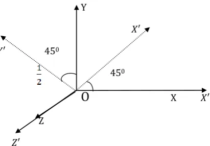
Rotation about Z-axis
Keeping Z-axis fixed and rotating the co-ordinate system through an angle П/4 to give a new co-ordinate system (X′ , Y′ , Z′ ) as
The direction cosines relating the Z-systems are given by
X Y Z
X’ 0 -1 0
Y’ -1 0 0
Z’ 0 0 1
Y
𝑋′
𝑌′
450
450
O
X 𝑋′Z
𝑍′
Figure 3. Rotation of XY-plane around Z-axis by П/4.
X Y Z
X’ 1/ 2 1/ 2 0
Y’ -1/ 2 1/ 2 0
By the Equations (3.2a-f) and (3.3a-f), we have
ℑ′1 = (ℑ1+2ℑ6+ℑ2) ℑ′2= (ℑ1-2ℑ6+ℑ2)
ℑ′3= ℑ3 ℑ′4= (ℑ4-ℑ5)
ℑ′5 = (ℑ4+ℑ5) ℑ′6= (ℑ2-ℑ1) 6.7
and,
From Equations (6.7) and (6.8), we have
Comparing the coefficients of e1 (or e2)
Then, the system of Equation (6.6) reduces to
6.9 There are only two elastic constants C11
and C12 in the stress-strain relations. Such a
medium in which the elastic property is repre-sented by only two elastic constants is called isotropic medium. Generally, in such a me-dium C11 = +2µ and C12 = . The
stress-strain relation is represented by
where Θ represents the cubical dilation, & µ are Lame’s constants,
δ
if represents theKronecker’s delta.
TRANSVERSE ISOTROPY AND AZIMUTHAL ANISOTROPY
The transverse isotropy is elastically equivalent to hexagonal symmetry with verti-cal axis symmetry. Keeping the Z-axis fixed and rotated the two axes at an angle Θ. The stress-strain relations remain invariant under this transformation. The direction cosines for the transformation are given by
By the Equations (3.2a-f) and (3.3a-f), we have
ℑ′1 = cos2Θ ℑ1 +2sinΘ cosΘ ℑ6+sin2Θ ℑ2
ℑ′2 = sin2Θ ℑ1 - 2sinΘ cosΘ ℑ6+cos2Θ ℑ2
ℑ′3 = ℑ3
ℑ′4 = - sinΘ ℑ5 +cosΘ ℑ4
ℑ′5 = cosΘ ℑ5 +sinΘ ℑ4
ℑ′6 = -sinΘ cosΘ ℑ1+cos2Θ ℑ6-
sin2Θ ℑ
6+sinΘ cosΘ ℑ2 7.1
and,
e′1 = cos2Θe1+sinΘ cosΘe6+sin2Θe2
e′2 = sin2Θe1 - sinΘ cosΘe6+cos2Θe2
e′3 = e3
e′4 = - sinΘe5+cosΘe4
e′5 = cosΘe5+sinΘe4
e′6 = - 2sinΘcosΘe1+cos2Θe6 - sin2Θe6
+2sinΘcosΘe2 7.2
Using Equations (5.3), (7.1) and (7.2), we get
ℑ′1 = cos2Θ ℑ1 +2sinΘ cosΘ ℑ6+sin2Θ ℑ2
or C11e′1 + C12e′2 + C13e′3
𝑒’
1=
12(e
1+2e
6+e
2)
𝑒’
2=
12
(e
1-2e
6+e
2)
𝑒’
3= e3
𝑒’
4=
12
(e4-e5)
𝑒’
5=
12
(e4+e5)
𝑒’
6= (e2-e1) 6.8
ℑ′
6=
12(
ℑ
2-
ℑ
1)
or C
66𝑒’
6=
12(C
12e
1+ C
11e
2+ C
12e
3-C
11e
1
- C
12e
2- C
12e
3)
or C
66(e
2-e
1) =
12
[(C
12- C
11)e
1-(C
12-C
11)e
2]
C66=
12(C11-C12).
ℑij = 𝜆
Θ
𝛿
𝑖𝑗+2µeij, (i, j = 1, 2, 3) 6.10
X Y Z
X’ Cos Θ Sin Θ 0
Y’ -Sin Θ Cos Θ 0
= cos2Θ [C
11e1 + C12e2 + C13e3] +2sinΘcosΘ
C66e6 +sin2[C21e1 + C22e2 + C23e3]
or C11[cos2Θ e1+ sinΘcosΘ e6+sin2Θe2]+ C12
[sin2
Θ e1–sinΘcosΘ e6+cos2Θe2]+C13e3
= cos2[C
11e1 + C12e2 + C13e3]+ 2sinΘcosΘ
C66e6 +sin2Θ[C21e1 + C22e2 + C23e3]
or (C11cos2Θ+C12sin2Θ)e1+(C11sin2Θ+C12cos2
Θ)e2 +C13e3+(C11-C12)sinΘcosΘe6
= (C11cos2Θ+C12sin2Θ)e1+(C12cos2Θ+C22sin2
Θ)e2 +(C13 cos2Θ+C23sin2Θ)e3
+2sinΘcosΘC66e6
Comparing the coefficients of e2 (0r e3) and
e6
C11sin2Θ+C12cos2Θ = C12cos2Θ+C22sin2Θ
which gives C11 = C22
and 2sinΘcosΘC66 = sinΘcosΘ(C11 – C12)
or C66 = (C11 - C12)/2 which gives C13
= C13 cos2Θ+C23sin2Θ or C13 = C23
By the relation ℑ′4 = - sinΘ ℑ5 +cosΘℑ4 we
have
C44e′4 = - sinΘ C55 e5+cosΘ C44 e4
or C44 [- sinΘe5+ cosΘe4]= (C44 cosΘ) e4 – (C55
sinΘ)e5
or (C44 cosΘ)e4 – (C44 sinΘ)e5 = (C44 cosΘ) e4 –
(C55 sinΘ)e5
or C44 = C55
Thus, under this symmetry
C11 = C22 ; C44 = C55 ; C13 = C23 ; C66
= (C11 - C12)/2
Thus, in the crystallographic system, the stress-strain relations are given by
7.3 There are only five elastic constants in the stress-strain relation. A medium in which the stress-strain relations are represented by only five elastic constants, is known as transverse
isotropic (also known as radially anisotropic, axisymmetric and cylindrically symmetric) medium. A transversely isotropic material can be characterized by five independent elas-tic coefficients C11, C33, C13, C44, C66 that
rep-resent its aggregate properties.
CONCLUSION
We have discussed different elastic con-stants in the anisotropic elastic solids. We may conclude the following points:
1. The number of elastic constants in the generalized anisotropic medium is 21. 2. The number of elastic constants in the
monoclinic medium is 13.
3. The number of elastic constants in the orthotropic medium is 9.
4. The number of elastic constants in the anisotropic medium with hexagonal symmetry is 6.
5. The number of elastic constants in the transversely isotropic medium is 5. 6. The number of elastic constants in the
cubic medium is 3.
7. The number of elastic constants in the isotropic medium is 2.
REFERENCES
1. Singh SS & Tomar SK (2008). qP-wave at a corrugated interface between two dissimilar pre-stressed elastic half-spaces. J Sound Vibra, 317, 687-708.
2. Song X & Helmberger DV (1993). Anisotropy of Earth’s inner core. Geophys Res Lett, 20, 2591-2594.
3. Musgrave MJP (1970). Crystal Acoustics. Holden-Day, Inc., San Francisco, USA.
4. Crampin S (1981). A review of wave motion in anisotropic and cracked elastic media. Wave Motion, 3, 343-391. 5. Singh SS (2008). Quasi nature of elastic waves in
anisot-ropic elastic medium. Sci Vis, 8, 152-155.
6. Auld BA (1973). Acoustic Fields and Waves in Solids. John Wiley & Sons, New York.
7. Malvern LE (1969). Introduction to the Mechanics of a
Continuous Medium. Prentice-Hall, Inc. Englewood Cliffs,
New Jersey.
Thus, in the crystallographic system, the stress-strain relations are given by
ℑ1 C11 C12 C12 0 0 0 e1
ℑ2 C12 C11 C12 0 0 0 e2
ℑ3 = C12 C12 C11 0 0 0 e3 7.3
ℑ4 0 0 0 C44 0 0 e4
ℑ5 0 0 0 0 C44 0 e5
ℑ6 0 0 0 0 0 (C11 - C12)/2 e6