Themed Section: Science and Technology
Control of Renewable Power Generation Systems by using
Fuzzy Logic Controller Based Synchronous Power Controller
B. Charan Kumar Reddy 1, M. Chethan 2, T. Madhuranthaka 3
1 PG Scholar, Department of EEE, Sri Venkatesa Perumal College of Engineering &Technology, Andhra
Pradesh, India
2Assistant Professor, Department of EEE, Sri Venkatesa Perumal College of Engineering &Technology, Andhra
Pradesh, India
3HOD, Department of EEE, Sri Venkatesa Perumal College of Engineering &Technology, Andhra Pradesh,
India ABSTRACT
In this paper presents the expanding measure of renewable power generation systems is a testing issue for the control and operation of the electrical systems. One of the principle issues is their absence of idleness, which is turning into a more prominent issue as much as the share of the power plants in view of customary synchronous generators gets decreased. In such manner the new system codes request that these plants give new functionalities, for example, the frequency support and dormancy imitating. A synchronous power controller for system connected converters is proposed as a decent answer for the renewable generation systems with energy storage. It gives latency, damping and adaptable droop qualities. Not quite the same as the reliable replication of the swing condition of synchronous machines, an option control structure is proposed, by which the damping and inherent droop slope can be series freely to meet the requirements in both progression and frequency directions.
Keywords: DC-AC power conversion, Inertia emulation, Power generation control, Synchronous power controller, Fuzzy Logic Controller, PI Controllers, Solar Generation, Swing Equation, and Grid Code
I.
INTRODUCTIONCustomary generation plants in view of renewable energy sources (RES) go about as network bolstering systems, which convey the greatest power from the essential source to the grid. As much as the infiltration of the RES generation plants expands, the lacking latency in the entire system could undermine its working soundness. Hence, the control targets and flow of the system connected converters should be switched in accordance with take more duties in grid supporting issues, for example, dormancy copying, frequency direction and voltage regulation.
The droop control procedure has been actualized in the control of grid connected converters. Despite the fact that the external droop circles permit the grid connected converters to modify the relentless state control infusion as per the request of the network, the transient practices of these Converters are sufficiently bad. The absence of dormancy is still a downside, which can't be enhanced by load control without risking the steady operation of a grid connected converter.
approach that has been drawing a considerable measure of interests in the current years. This pattern is started by the way that traditional grid synchronization calculation like Phase-locked loop (PLL) presents not idleness attributes, and the elements of any supporting technique is influenced by the intrinsic progression of the PLL. Additionally, a PLL may negatively affect the control execution under powerless ac networks.
A control usage conspires for the copying of SG is proposed. In which the circle filter of the traditional PLL is altered to imitate the dormancy and damping
qualities. Other comparable outline or
recommendations fusing inactivity and damping in a PLL can be found. In view of the methodology, the dormancy impact is just connected to the system frequency, and does not basically exist while responding to the power input varieties. At that point the bothers in the dc side will be straightforwardly transmitted to the air conditioner side without latency. What's more, the dormancy impact does not exist in island operation in view of this sort of outline.
Another execution technique for copying SG is proposed and broke down, in which the PLL is substituted by a dynamic power synchronization loop. Despite the fact that this technique has indicated preferences in the interconnection of feeble ac matrices, the inactivity and swaying damping are not particularly tended to, and it must be switched to a PLL-based vector current control under extreme ac deficiencies.
A torque synchronization loop is outlined considering inertia and damping attributes. A comparable procedure is additionally embraced. The creators propose a synchronous power controller displaying idleness and damping attributes, and especially a virtual permission structure is proposed. The creators demonstrate that the latency can likewise be executed in the micro grid droop controller, making utilization
of the primary request low-pass filter which is generally utilized just to damp the estimation clamor. The previously mentioned outlines join the swing condition innately in the power directing circle, in this manner the power synchronizing impact will be available in both grid connected or island operation. By and by, the damping impact and the power-frequency droop incline are obliged by each other. Because of this, a great parameter for the droop highlight may prompt to a deficient damping, and in the different way, damping parameter could offer ascent to an undesired droop slant. Then again, since the droop attributes are normally consolidated in the power controlling circle, a settled power control can't be specifically accomplished regardless of the possibility that it is required in a few applications. The creators propose to utilize an extra PI controller with a virtual droop to modify the damping filter to accomplish a settled power control if necessary, however the request of the shut circle switch capacity will build, in this manner the dynamic investigation and tuning of parameters turn out to be more complex.
Figure 1
This project proposes a synchronous power controller
with inertia, damping and flexible droop
attributes independently. Also, an express connection among the controller gain, latency, damping coefficient and droop slope is given, and in this way the proposed strategy makes an adaptable control worldview conceivable in which the controller increases can be adaptive.
II.
OVERALL CONTROL STRUCTUREThe proposed control circle controller depends on the general synchronous power control (SPC) motorizing appeared in Figure 1. This control plan is predominantly portrayed by two hinders, the electromechanical piece and the virtual permission
square, which are separately depicted.
Notwithstanding the control plot appeared in Figure 1, external circles can be included. Contingent upon the prerequisites of the network and the design and control system at the dc side, the external circles can differ. Regularly a Q-V hang controller is included for feeble lattice support and island system shaping. What's more, considering the constrained power save from the dc side, an external P-Vdc hang control can likewise be incorporated as an expansion to the P-f qualities.
In view of the general control structure, the inactivity can be basically fused in the electromechanical control circle by legitimately outlining the power circle controller.
As appeared in Figure 1, the power circle controller creates a virtual synchronous frequency ω, which is then coordinated to a stage flag θ. consolidating the stage flag θ and the greatness flag E (produced by the receptive power controller), the virtual electromotive compel e will be created by the Voltage Controlled Oscillator (VCO). For this situation a PI controller is executed in the responsive power control circle.
The virtual permission structure received is chosen as the structure of the internal control circles, which is appeared in Figure 2. It is a copying of the output
impedance of SG. This piece assumes a key part in load sharing and shows a characteristic voltage greatness hang highlight for network voltage bolster.
Figure 2. Virtual admittance emulating the electrical characteristics of synchronous machines.
Contrasted and the outstanding virtual impedance structure, the virtual permission structure copies the output impedance without prompting to the troubles in usage. The principle focal points lay on the viability for the entire scope of consonant frequencies and the straightforwardness in the inward circle execution.
As indicated by the electrical qualities of the synchronous machines, the produced dynamic power can be approximated to (1), considering that the output impedance of SG is predominantly inductive.
Where ΔP is the incremental generated power and Δδ is the incremental phase-angle difference between the virtual electro-motive power e and the grid voltage v in each phase. The admittance gain is expressed as,
Where E and V are respectively the RMS values of e and v, and X the value of the reactance provided by the virtual admittance.
Based on (1), the inner control loops can be simply modeled as an admittance gain since it has much faster dynamics compared with outer loops. So it avoids the complexity in the analysis of power loop.
III.
ELECTROMECHANICAL BLOCKlike the one of a SG. Regardless of the possibility that the network voltage edge θ lattice is obscure, the synchronous precise speed ω can simply be changed in accordance with in like manner move the heap edge δ. Along these lines the dynamic power is directed.
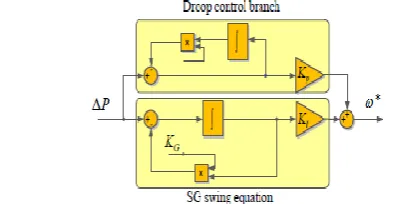
Figure 3. Modeling of active power control loop converter
As the fundamental concentration of this paper, a power circle controller is proposed. In the accompanying, the current systems that for all intents and purposes actualize the swing condition of SG are broke down to start with, and the limits of the current strategies are appeared. At that point an option controller is proposed, and the numerical relationship between the trademark parameters and the control parameters is shown.
A. Mechanical Power Loop Controller
The SG swing equation can be expressed as (3) in terms of power, for small signals of the rotor angular frequency ω around the synchronous frequency.
In (3), Pmech is the information mechanical power, Pelec
the output electrical power, ωs the synchronous rakish frequency, J the snapshot of inactivity and D the damping parameter. Despite the fact that the damper twisting of SG can give the damping impact, it is moderately restricted. Considering this reality, the damping of the power circle can be enhanced and advanced for control of grid connected converters. Subsequently, the damping term is considered and additionally the latency.
In view of the swing condition, the type of GPLC(s) can be outlined as appeared in (4), which is referenced as mechanical power circle (MPL) controller in this paper.
According to (4), the resulting closed-loop transfer function is obtained and shown in (5a).
Equation (5a) is given in the particular shape as a relationship of the second request parametric switch work, for which the time reaction is characterized by the parameters ωn and ξ. Besides, ωn and ξ are likewise connected to the damping and idleness parameters of the SG swing condition through (5b) and (5c).
To ensure the neighborhood strength of the system, ξ must be determined more noteworthy than zero.
Rather than utilizing the snapshot of idleness J to assign the latency attributes, the inactivity consistent H is regularly received, which is characterized in (6), which means the time it takes to quicken the rotational speed from zero to ωs utilizing full power SN.
For analyzing the dynamics of the power control circle, the reaction to frequency unsettling influences likewise should be considered. In the demonstrating, the matrix frequency can be connected to the lattice stage edge by an integrator. As per Figure 3, taking ωg as the variable while taking P as the capacity, the connected transfer function (P-f response) is shown in (7).
then combining (7) and (8), the intrinsic droop ratio
of the MPL controller DP(MPL) is expressed in (9).
It is seen that the MPL controller realizes a constant power synchronizing conduct the length of the lattice frequency digresses from the ostensible esteem. Be that as it may, the hang proportion DP is obliged by the dormancy and damping parameters that prompt to a tradeoff in the parameters setting.
B. Boundaries of the MPL Controller
To further demonstrate the limitations of the MPL controller in parameters tuning, the matrix frequency deviation rate that concentrates the full evaluated control from the converter is utilized as the marker of the hang attributes, which is spoken to by 1/R. The connection amongst DP and 1/R is appeared in (10).
Then the interaction among inertia, damping and droop slope defined by the MPL controller is obtained as written in (11), which is derived combining (5c), (6), (9) and (10).
Where Xpu represents the per-unit value of the
reactance of virtual admittance and is expressed in (12).
Equation (11) shows the interaction among H, ξ, Xpu
and 1/R. And since the values of H and Xpu can be
pre-fixed respectively considering the design requirement, the challenge mainly lies in the restriction between ξ and 1/R.
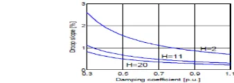
This restriction is visualized in Figure 4, where H is specified to 2, 11 and 20 respectively in three cases. The grid nominal frequency is set to 50 Hz and Xpu is set to 0.3 to specify the model.
Figure 4. The relation between the droop slope 1/R
and the damping coefficient ξ.
As appeared in Figure 4, once the damping coefficient ξ is tuned and fixed, the hang incline will be settled, as well. However then again, the hang incline should be indicated considering the frequency variety of the utility lattice and the power save of the era plants.
For conventional synchronous generators, a
commonplace scope of hang incline is 4% < 1/R < 5% . In any case, for RES-based era plants, 1/R may must be more noteworthy considering the power save that is in fact and financially doable. In the situations appeared in Figure 4, 1/R is underneath 3%. On the off chance that 1/R is required to be more prominent, ξ must be diminished, which undermines the damping execution.
This issue won't exist if the matrix is commanded by the converters controlled with the MPL controllers, since a little estimation of 1/R prompts to more
grounded impact in contradicting frequency
deviation. Notwithstanding, if the aggregate era is commanded by conventional synchronous generators, the frequency variety in the network can bring about regular immersion or low power quality infusion of the era units that have a little estimation of 1/R.
C. Configurable Natural Droop Controller
Figure 5. The proposed power loop controller.
Other than the implementation of the swing equation of a SG, a droop branch is included in parallel for
controlling the P-f droop slope in steady state. In this
way it adjusts the offset of the power transfer function by introducing a new degree of freedom. The structure of the droop branch is developed in the way that it shares the same denominator with the transfer function of the swing equation. In this manner the order of the power regulating loop does not increase. In a practical implementation the integrators in the controller can be discretized using the Tustin trapezoidal method for an accurate equivalence.
The transfer function of the proposed controller is generalized as written in (13), which is referred as configurable natural droop (CND) controller in this paper.
Contrasted and the MPL controller, the CND controller gives an extra level of flexibility without expanding the request of the power directing switch work. Furthermore, it gives a characteristic P-f hang highlight which can be designed in-ward to the dormancy and damping parameters.
Substituting the power circle controller obstruct in Figure 3 with the expression (13), the subsequent shut circle switch capacity is appeared in (14a). The damping coefficient and characteristic frequency are separately communicated in (14b) and (14c).
Even though (14a) has an alternate expression in the numerator contrasted and the standard second-arrange parametric switch work, the denominator of the system is the same. In this way, keeping in mind the end goal to put the shut circle posts in the left half plain to ensure the steadiness, ξ still must be indicated more noteworthy than zero.
The P-f reaction of the CND controller is appeared in (15),
Where (16) is obtained.
As indicated by (14b), (14c) and (16), by determining the control parameters KP, KI and KG, the idleness, damping and hang attributes can be individually given. In addition, the normal frequency ωn can be meant the latency consistent H by joining (5c) and (14c) to liken the ωn from two cases. Alternatively, DP can be set to zero if the plant is allocated to have a settled power control.
IV.
CONTROL PARAMETERS SETTING
the usage the calculation for ascertaining the control parameters in view of (14b), (14c) and (16) can be installed in the converter controller, however might be initiated when the auxiliary orders are refreshed. As specified in the previous segment, DP is the hang proportion that should be resolved in light of the frequency variety of the utility matrix and the practical power save. H can be assigned considering the dormancy consistent of the SG that has a similar power level. Furthermore, the damping coefficient ξ can be set considering the normal esteem range to make a steady and under-damped system. 10<<ξ So as to further tune ξ, the investigation on progression is done in view of the scientific move capacities given in the previous area. A unitary stride information is given to the shut circle switch work (14a), and the impact of ξ on the settling time and overshoot of the time reaction can be ascertained.
V.
PROPOSED RESULTS
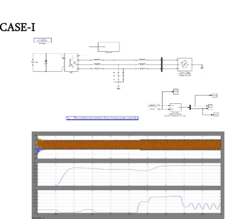
CASE-I
Figure 7. Active power step response of the converter connected to weak grid: The proposed synchronous
power control. b)Active Power c)Reactive Power
CASE-II
Figure 9. The islanding action and load variations of a three-port system.
Figure 9. The islanding action and load variations of a three-port system. a)Grid Voltage b)Load Voltages c) Converter1 active Power d) Converter2 active power
e) Converter3 active Power f)Load active Power
VI.
EXTENSION SIMULATION
FUZZY LOGIC CONTROLLER
Figure 7. Active power step response of the converter connected to weak grid: The extension synchronous
power control. b)Active Power c)Reactive Power
CASE-II
Figure 8. The islanding action and load variations of a three-port system.
Figure 9. The islanding action and load variations of a three-port system. a) Grid Voltage b) Load Voltages c) Converter1 active Power d) Converter2 active power
e) Converter3 active Power f) Load active Power
Comparison table of proposed and extension Table 1
Proposed Extension
Case -I 43.64% 42.64%
Iactual
Case -II 2.45% 1.30%
Vgrid
Vload 1.24% 0.48%
VII.
CONCLUSIONS
This paper proposed a synchronous power controller
with inertia, damping and flexible droop
characteristics for grid-connected power converters. The proposed controller shows more flexibility compared with the existing inertia emulation techniques, since it avoids the constraint between the damping and droop characteristics in the power
regulating loop. Therefore, an outer P-f droop
controller accompanied by a dedicated PLL is not needed for any operation phase, and the trade-off in designing the bandwidth of the droop loop low-pass filter is avoided. Besides, the fixed power control can be easily achieved in spite of grid frequency variations.
VIII.
REFERENCES
[1].Q. C. Zhong and G. Weiss, "Static synchronous
generators for distributed generation and renewable energy," in Proc. PSCE, 2009, pp. 1–6.
[2].K. De Brabandere, B. Bolsens, J. Van Den Key bus,
A. Woyte, J. Driesen, and R. Belmans, "A Voltage and Frequency Droop Control Method for Parallel Inverters," IEEE Trans. Power Electron., vol. 22, no. 4, pp. 1107–1115, 2007.
[3].J. M. Guerrero, J. C. Vasquez, J. Matas, L. G. De
Trans. Ind. Electron., vol. 58, no. 1, pp. 158–172, 2011.
[4].T. Loix, K. De Brabandere, J. Driesen, and R.
Belmans, "A Three-Phase Voltage and Frequency Droop Control Scheme for Parallel Inverters," in Proc. IECON, 2007, pp. 1662–1667.
[5].J. Rocabert, A. Luna, F. Blaabjerg, and P.
Rodríguez, "Control of Power Converters in AC Micro grids," IEEE Trans. Power Electron., vol. 27, no. 11, pp. 4734–4749, 2012.
[6].K. Rouzbehi, A. Miranian, A. Luna, and P.
Rodriguez, "A generalized voltage droop strategy for control of multi-terminal DC grids," IEEE Trans. Ind. Appl., vol. 51, no. 1, pp. 59–64, 2013.
[7].H. P. Beck and R. Hesse, "Virtual synchronous
machine," in Proc. EPQU, 2007, pp. 1–6.
[8].L. Zhang, L. Harnefors, and H. P. Nee,
"Power-synchronization control of grid-connected