Platinum Alloy Permanent
Magnets
THE DESIGN OF MAGNETIC CIRCUITS FOR PLATINAX I1
By
L.
A. Ford,
B . s ~ .
Research Laboratories, Johnson Matthey & Co Limited
In applications of this type, it is essential for magnetic circuits to be properly designed, so as to ensure that effective use is made of
the properties of the magnetic material. This is particularly important when a high per- formance material such as Platinax I1 is to be used, and necessitates redesign of the magnetic circuit if a material of lower per- formance is to be replaced.
It is some years since investigations by a Johnson Matthey research team into alloys of
the cobalt-platinum system led to the de- velopment of Platinax 11, an extremely powerful permanent magnet material.
Since then the principal applications of this alloy have been for miniaturised units, such as hearing aids and electric watches, where advantage is taken of the exceptionally high magnetic performance of the material, and in instruments where powerful magnets must be subjected to highly corrosive conditions, such as meters that measure and control the flow of corrosive liquids.
Operating Characteristics
The performance of a permanent magnet material is shown by its demagnetisation curve. A typical curve for Platinax I1 is given in Fig. I illustrating, together with the derived energy-product curve, the three properties of residual induction (BJ, coercive force (H,) and maximum energy-product
Although these figures are valuable in making comparisons between different mater- ials, they give only an approximate guide to the way a magnet will function in service. Final performance depends very largely upon the point at which the magnet works on, or adjacent to, its demagnetisation curve. This is governed by factors that can often be con- trolled, such as magnet shape and the type of external circuit in which it operates.
For example, the working point of a magnet that operates free from stray magnetic fields lies on the demagnetisation curve provided that the magnet is magnetised in its circuit and is not subsequently disturbed. Its magnetic performance is determined by the amount of energy that it makes available, and this is proportional to the product (B xH) at
the working point. The available energy
@H)rnax.
Plalinax 11, fl: cobalt-platinurn allw, is one of the most powerful permanent
magnet materials knwvn. Because of its high performance, its principal uppli-
cations are in miniatwised tinits where
size and weight considerations are ofthe
utmost importonce, or where the geo-
metry of d e magnet excludes the use
of odier materials. I t is reudib fabri- cated and machined, mabiing magnets of complex shape to be mlariufac!ured to
close lolerancos, and it will operate for long periods i n highly corrosive environ- ments. To obtain fhe maximum advani- age from its use, it i s necessary to design
magnetic circuits carefully so IW to exploit as fully as possible t h magnetic characteristics of the alloy. Data are
given in this o r t i c k that will assisc engineers to make the most effeccive use
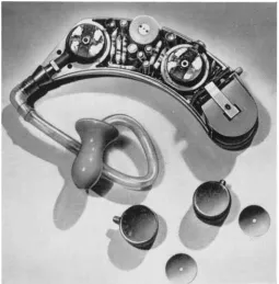
T h i s hearing aid by Forti- phone Limited contains two Platinax 11 magnets in
disc f o r m , one .003 inch thick by -& inch and the other .005 inch thick b y fc inch. By the use of Platinax I I magnets tlLe c o m b i n e d m i c r o p h o n e , a m p l i f i e r a n d e a r p h o n e unit has been considerably reduced in size and weight without loss of sensitivity
therefore reaches a maximum value at the (BH),, position and in order to obtain maximum economy of magnetic material a magnet should, whenever possible, operate at this point, i.e. at BdHd in Fig. I .
B H PRODUCT
I o7 5 I06
I I 7000
8,
-
6 4 8 0-
r I
- so00 - 3 0 0 0 -1000
H (OERSTEDS)
6000
5000
4 0 0 0
_-
.
VI VI 3 0 0 0 jm
v
2000
1000
The working points of four cylindrical magnets are shown in Fig. 2 on the demagneti-
sation curve for Platinax 11. Each magnet was measured in three separate circuits, covering a wide range of self-demagnetising conditions.
It can be seen that even under arduous ‘open-circuit’ conditions (Fig. za) relatively short Platinax I1 magnets operate satis- factorily. The addition of a cylindrical iron extension produces some improvement in economy (Fig. zb), while still further im-
provement is obtained by placing the magnets in an iron yoke (Fig. zc). The effect of the improvement is clearly shown hy comparing the sizes of magnets operating at approxi- mately (BH)ma,. For an open-circuit magnet, a length/diameter ratio of one-half is required, whereas for a magnet operating in the yoke
a: O P E N C I R C U I T
A
O 6,c H
1000
I ' I I
- 5 0 0 0 - 3 0 0 0 - 1000 FIELD H (OERSTEDS)
7000
6000
-
v)5000 $ <
4000
-
z 3000
U
2 0 0 0
g
LOO0
-5000 '
-
3 0 0 0 - 1000FIELD H (OERSTEDS)
Fig. 2 A magnet's performance i s governed b y its shape and the type of circuil in which it works. iWeaaurement of the working points of Platinax 1 I
magnet systems shows that ( a ) high performance is
obtained f r o m short, open-circuit magnets. Greater economy i s achieved by ( b ) adding a short iron extension and b y ( c ) placing the magnet in a n iron
yokr
f B
0
Fig. 3 T h e working p o i n t of a magnet subjected to a demagnetisingfield follows the curve f r o m M to
N. W h e n the$eld i s removed, a partial recovery i s made and the working point moves along a recoil line to the position P. T h e performance of the
magnet undergoes a corresponding change
the ratio is reduced to one-quarter, represent- ing a saving of 50 per cent in magnet material. The overall size of the magnetic circuit is naturally increased by such measures, but this may be justifiable if space and weight limitations are not severe.
Recoil Permeability
A magnet that operates in a demagnetising field suffers a loss in performance that is only partially regained when the field is removed. The extent of its recovery is determined by the recoil characteristics of the material from which it is made. This can be appreciated by considering a magnet that operates at a point M on the demagnetisation curve (Fig. 3) until, on being partially demagnetised by a
field, its working point follows the curve to
the point N. I n the absence of further demagnetising forces it will remain there until the field is removed, whereupon, instead of retracing the curve to M, it will move along a recoil line to the point P, which becomes the new working point. The performance of the magnet undergoes a corresponding change in magnitude.
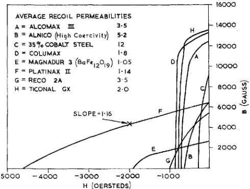
Fig. 4 The demagnetisa- tion curves of various per- manent magnet materials are shown, together with values of average recoil per- meability. Unlike high- energy materials having more “rectangrdar” curves, the recoil lines of Platinax
I I lie close to the main BH
curve for a relatively large range, indicating high capacity to recover from the eflects of demagnrtising .fields
I
16000AVERAGE RECOIL PERMEABILITIES A = ALCOMAX m
B = ALNICO ( H i g h Coercivity)
C = 357oCOBALT STEEL D COLUMAX
5.2
E = MAGNADUR 3 ( B ~ F ~ ~ ~ o , ~ ) 1.05 F = PLATINAX II
G = R E C O 2 A H = T K O N A L GX
SLOPE-1.16
-5000 - 4 0 0 0 -3000 -2000 -1000
H (OERSTEDS)
the same slope, point P would coincide with point M, and the change in energy would be zero.
Platinax I1 is one of the few materials whose recoil lines lie very close to the main BH curve. Many other high-energy materials have demagnetisation curves of more rectangular shape, and although these exhibit good recoil properties over the upper sections of the curve, they are not maintained where the curves become steep. As a result, a de- magnetising field that causes a temporary lowering of working point on to the steep section of the curve causes, on its removal, a substantial reduction of available energy.
Comparisons, made in the table, between the slopes of the recoil lines (ur) and the demagnetisation curve for Platinax IT, show the remarkable similarity in values around the (BH),, point. It is evident that mignets operating in demagnetising fields at these
Recoil Pronerties of Platinax I1
14000
l 2 0 0 0
1 0 0 0 0
aooo
2
3
4
6 0 0 0
40#
2 0 0 0
points would recover almost completely on removal of the field.
The demagnetisation curves of some per- manent magnet materials are shown in Fig. 4,
together with published values of average recoil permeability. Curves for the more common high-energy materials, such as Ticonal GX and Alcomax 111, are clearly of a more rectangular form.
The Magnetic Circuit
Energy produced by a permanent magnet is
used in two ways. Its purpose normally is to provide a flux across a gap, but to do this energy is also used in losses around the remainder of the circuit. In practice, wasted energy generally far exceeds that which is usefully employed and in order to ensure adequate performance these losses must be taken fully into consideration.
The losses are of two types. Those requiring
Magnet W o r k i n g Point Recoil Slope of (oersted) (gauss) (!4 Curve
-2000 4000 1.13 1.16
-3000 2800 1.14 I .34
-3600 I900 1.16 1.66
H 6 Permeability Demagnetisation
least compensation are the “series” or reluctance losses caused by inadvertent air gaps and by any associated iron path. These can be catered for by increas- ing the length of the magnet by a small factor, usually between 5 and 40
The second type of loss is caused by leakage
flux, that is flux which passes outside the useful gap and therefore cannot be used. This produces a very considerable effect on magnet performance, since it generally wastes be- tween 50 and 95 per cent of the total energy produced. Its magnitude depends mainly upon circuit geometry and this allows certain measures to be taken to avoid unnecessarily high losses, for example, by ensuring that circuit components are spaced sufficiently far apart. Unfortunately leakage losses cannot be eliminated, and so compensation must be made for them by increasing the cross-section of the magnet, generally by a factor of between
2 and 20 times.
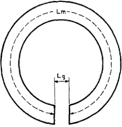
Fig. 5 A ring magnet with a short air gap
Whenever possible it is an advantage to make the largest increase at the point farthest from the gap (i.e. at the neutral point) as this section must be large enough to supply the total of both useful and leakage flux. As the gap is approached, the amount of “leakage” to be provided for diminishes, and the re- quired increase in section can be progressively reduced.
The problem of finding suitable dimensions is approached by considering a hypothetical magnetic circuit in which all the energy produced by the magnet is usefully employed. This condition is nearly achieved by the simple magnet shown in Fig. 5, consisting of a
ring having a very short air gap across which all the flux is assumed to flow uniformly.
Summing the magneto-motive forces around this circuit:
LmHW--LgHg= 0
or L,Hw=LgHg (1)
where L,= magnet length
BW,Hw = working point of maznet
Lg=length of air gap Hg==field in air gap
Furthermore the flux in the magnet is the same as that in the air gap hence:
&Arn= BgAg (2)
where Am = magnet area
Ag -gap area &=gap flux density
( ;Hg numerically) From equations (I) and (2):
Am’ __ BgAg B W
Vm=LgHg‘Ag BwHw
where V, =- magnet volume
Therefore, applying the factors to correct for circuit losses :
L,-=LgHg X K,
HW
Am’BgAgXKz
B W
BwHw
-
-
Vm -LgHi2Ag X K1Kz
where in general K, lies between 1.05 and 1.4 and K 2 lies between 2 and 20.
Evaluation of the constants can sometimes be made, but this involves long and often complex calculations. It is far more con- venient to base a design upon past experience wherever possible, and to assist in this measurements have been made on specimen Platinax I1 magnet systems.
Magnetic Field
Measurements
Figs. 6 and
7
showflux
distributions close3 0 0 0
2000
h
ul VI
2 4
2%
w
9
LL
I000
,
I , 8 1 70/, D
DISTANCE FROM MAGNET
Fig. 6 T h e axial fields produced b y “open- circuit” Platinax magnets vary w i t h distance f r o m the magnet. T h e effect of the increased self- demagnetisation of shorter magnets is illustrated
by the lower j?elds they produce
demagnetisation. The values obtained with open-circuit magnets indicate that fieIds diminish rapidly with distance.
Some improvement in maximum field was apparent when the open circuit conditions were moderated, although the tendency for fields to diminish rapidly with distance still
2000
-
ulUI
3
Q:
y
1000 WLL
-
t1
EDGE FIELD...
I
I N S
v 2 D
DISTANCE FROM MAGNET
4000
3000
,-.
3
2 -a
0
v
n
d
2000U
loco
D
G A P L E N G T H
D
Fig. 8 An improvement o n “open-circuit” working i s obtained by placing the magnet near a n iron plate. For a magnet with a n LID ratio of 1 , this results in a 4 0 p e r cent increase in the m a x i m u m
measured field
remained. This is illustrated in Fig. 8, which shows the field intensities at three positions in a variable air gap separating a magnet from an iron plate. Whereas the maximum field measured on an open circuit magnet with an L/D ratio of I was 2500 gauss (Fig. 6), when the same magnet was placed near the iron plate the maximum field in- creased to 3500 gauss.
Further improvements in performance were obtained by placing the magnets between iron cylinders of similar diameter, each having an L/D ratio of 4. The field intensities shown in Fig. 9 were obtained with the magnet in contact with one cylinder and separated by a short air gap from the other. Using this
Fig. 7 Edge fields produced by “open circuit” Platinax II magnels vary in a similar w a y to thosp o n the axis. However, because the magnetic field diverges to a much greater extent near the edge, the
W 1000
. -
.s
:
100-
x
e o --
-
m
Z
Fig. 10 Platinax ZZ magnets, i n common with x other types, lose performanre when heated. T h e rate
of loss i s high at$rst, but diminishes quickly until, after approximately three hours, a stage is reached where little further change occurs. A short prelimi-
2
6 0 -”
$
4o0 D
GAP LENGTH G A P LENGTH
12O0C
==Z,
zooo c\
25OoC35OoC
1 arrangement, the magnet having an L/D
ratio of I gave a maximum measured field of approximately 4,000 gauss.
Magnetic
Stability
I n designing a magnet for a particular job it is important to know how it will react when subjected to demagnetising forces. If mag- netisation is carried out before assembly into its circuit, for example, the magnet’s own
Fig. 9 Improved performance i s obtained b y extending the magnetic rircuit with iron cylinders. T h e increase in .field over “open-circuit” jigures ranges f r o m approximately 50 per cent f o r t h longest magnet (LID-
1 ) to nearly 250 per cent f o r the shortest (LID = ). The axial fields were measured at positions 1 , 2 and 3, and the edge Jields at positions 4, 5
and 6
demagnetising field causes it to operate on a recoil line. Further reductions in flux can occur as a result of careless handling before or during assembly.
Although Platinax I1 is highly resistant to demagnetising forces, it is good practice to safeguard against possible loss of per- formance by magnetising after assembly whenever possible. This is particularly true for very short magnets in which self-dernagnetising forces are high. Apart from safeguarding their performance, the likelihood of contamination from magnetic debris is reduced.
Apart from the demagnetisation forces encountered before assembly, magnets fre- quently operate in demagnetising fields that would, in normal circumstances, cause a
reduction in their performance. To provide for greater stability in service a magnet can
Fig. 10 Platinax ZZ magnets, in common with other types, lose perfurmanre when heated. The rate
of loss is high at$rst, bnt diminishes quichly until, after approximately three hours, a stage i s reached tohere little further change occurs. A short prelimi- nary heat treatment toill enable u magnet to operate
be stabilised beforehand by deliberately applying a demagnetising field slightly in excess of that to be encountered later.
Temperature Effects
In common with other magnetic alloys, the performance of Platinax I1 drops progressively with increase in temperature, as shown in Fig. 10. Following a moderate rise in tem- perature, performance may be restored by remagnetising after cooling, but at tempera- tures above 300 to 350°C the losses are caused by changes in alloy structure which can only be rectified by a special heat treatment. If a magnet is required to work at temperatures where these changes occur it will inevitably suffer a gradual deterioration in performance
unless steps are taken to stabilise it. This can be done by a preliminary heat treatment which, while reducing performance, ensures that no further deterioration occurs when the magnet is used at high temperature.
Often the most convenient method of fixing a magnet is by soldering or welding, either of which can cause a local deterioration. If magnetisation can be carried out after assembly the loss may not be permanent, especially in low temperature operations such as soft soldering.
Magnetic
Holding
Power
Forces of attraction between magnet poles that are in contact can be approximately calculated by using the formula:
Dz.53‘
m 0 . 0 ~ 5 ” AIR GAP
K 0.1‘‘ A I R GAP
n 0 . 2 ” A l . Q G A P
-
’Oo01
1l/
N S(A) NEAR A N IRON PLATE (8) BETWEEN IRON KEY EXTENSIONS
D SURFACES IN CONTACT
...
E
.2 -_ 2000
i
!
w V
a
I000
P
1
0 45O IRON POLE P I E C E ATTACHED TO MAGNET AND IN CONTACT WITH PLATE
( S E E DIAGRAM 1
-
0 . 5 I 0.5 I
qD RATIO OF M A G N E T
Force in dynes =B2A
where A=area of magnet pole face in cm2
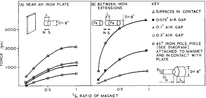
B =flux density at contact in gauss I t is sometimes necessary to know the forces that exist between magnetic components separated by an air gap. Specimen figures are shown in Fig. 1 1 illustrating the changes in
mechanical force that occur when the magnet length is altered. Throughout these tests, the diameters of magnets, and of extensions when used, remained at 0.8 inch.
I n general, forces produced by magnets operating near an iron plate increase steadily with increasing magnet length up to a length/ diameter ratio of approximately three-quarters. Beyond this point, further increases in length produce only small changes. A similar trend is shown by magnets operating between iron extensions, but in this case the curves begin to level off at a smaller length/diameter ratio. This agrees generally with the changes ob- served in working point in Fig. 9, and illustrates that the effective length of the magnet is increased by the additional iron.
-
87C Attempts to increase holding power by
attaching tapered iron pole pieces to the magnet have been unsuccessful, evidently because leakage is introduced which cancels the effect of possible flux concentration.
Economics
Platinax I1 contains 76.7 weight per cent platinum and naturally is of high intrinsic value. The magnetic characteristics as out- lined above are, however, quite exceptional and if due attention is paid to careful design, economic circuits are feasible. Platinax I1 obviously has its major applications for miniaturised circuits where it is necessary to have high flux in restricted spaces and where a small magnet can be fabricated from strip or wire.
Acknowledgment
Acknowledgment is due to the writer’s colleagues, D r J. C. Chaston, M r R. A.
Mintern, Mr R. J. Newman and Mr J. A.
Stevenson for their considerable help in the preparation of this article.
Alternating
Current
Polarisation
of Noble Metal Surfaces
THE
FORMATION OF PLATINUM AND PALLADIUM BLACKSIt has been observed that the reproducibility of a platinum electrode can be improved by a pre-anodisation treatment. The explanation of this effect has been in some doubt, and a recent paper by D r J. P. Hoare of the General Motors Research Laboratories (Electrochimica Acta, 19649,
(s),
599-605), throws new light on the matter.The effect of AC currents on small beads of noble metals was studied and it was noted that whereas black films were formed on the surface of platinum and palladium when treated in this way, no such films were observed on gold, iridium or rhodium. Some oxidation did occur on the gold and iridium and, if a DC current was superimposed on the AC so that the AC swing was not centred about a point more oxidising than that originally used, then the ‘black’ formation did
not occur on platinum or palladium and oxides were formed here also.
Dr Hoare deduces from his study that the mechanism of the formation of these blacks is via the dissolution of hydrogen, since it is well known that platinum and palladium will react readily with hydrogen, whereas gold, iridium and rhodium will not. The break-up of the surface is attributed by the author to the successive absorption and desorption of this hydrogen.