SOIL-TOOL INTERACTION AS A
REVIEW FOR DIGGING OPERATION
OF MINI HYDRAULIC EXCAVATOR
BHAVESHKUMAR P. PATEL
Lecturer, Mechanical Engineering, U. V. Patel College of Engineering, Ganpat University (GNU), Kherva - 382711, Dist: Mehsana, North Gujarat, India
DR. J. M. PRAJAPATI
Reader, Faculty of Technology and Engineering Maharaja Sayajirao University of Baroda,
Vadodara - 390002, Gujarat, India
Abstract:
Since the late 50’s hydraulics have been the systems of choice where high force-to-weight ratios are required. Today hydraulic excavators are widely used in construction, mining, excavation, and forestry applications. The skilled operator also cannot know about the terrain condition, soil parameters, and the soil-tool interaction forces exerted during excavation operation are required to find because these forces helpful for better design of the tool, backhoe parts and for trajectory planning. This paper focuses on the review of a work carried out by researchers in the same field which includes the fundamental of soil mechanics, soil tool interaction forces and various parameters affect on the soil-tool interaction during its actual digging action. This area is open to carry out further research to know the effect of various parameters on soil-tool interaction, prediction of digging trajectory and excavation forces and for robust design of backhoe mechanism.
Keywords: Soil-Tool Interaction, Digging, Resistive Forces, back hoe
1. Introduction
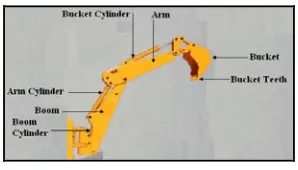
The surface mining of metals, quarrying of rocks, and construction of highway requires the rapid removal of soil and rocks. Typically explosives or mechanical techniques are used to pulverize the material and digging machine such as excavator load the material in to required place as well as dig also. The usual task of excavator is to remove the materials below the ground surface. An excavator is an engineering vehicle consisting of a backhoe with cabin for the operator and engine is used for power generation. Hydraulic system is used for operation of the machine while digging or moving the material [1].
Fig. 1 Basic parts of backhoe hydraulic excavator
2. Problem
A key problem in the modeling of digging trajectories is the estimation of resistive forces that are not only a function of the shape of the terrain, soil and tool parameters, but, also the controller that joints using force feedback, to fill the bucket. So the interaction between the tool (bucket teeth) and the terrain soil must be considered. The manufacturers of backhoe excavators have not upgrading the technology used on their machines, all the backhoe excavators sold in India until 2003 had 15 year old technology [3]. Earth moving process passages huge challenges to scientist and researchers due to the complexicity of the dynamical environment, in particular era of design, dynamics and controlling of the excavation process of an excavator. The design of all excavation machinery and the attachments are very as per their functional requirements and depends on their applications. So, herein the greatest opportunity for model development to predict soil-tool interaction forces for robust design of the tool as well as these forces helpful for trajectory generation for excavation task. The following section highlights the review on soil tool interaction to carry out the interaction forces and generation of tool trajectory.
3. Soil-Tool Interaction
A. M. Zein Eldin and Abdulrahman Al-Janobi, in 1995, have carried out a review on the effects of the operating variables on soil-tool interaction evaluation parameters. This review, therefore, involves studies to understand how the evaluation parameters are affected by the operating conditions of the soil-tool system. These parameters can be grouped into: 1. Tool parameters. 2. Soil parameters. 3. Soil-tool interface parameters, and 4. Surcharge conditions. Different techniques have been used to study soil tool interaction. They can be broadly grouped into two procedures: theoretical and experimental. Whatever approach is used, results are usually compared with earlier investigation in the literature. After review they have concluded that relatively extensive work has been documented on the effects of tool and soil parameters on some soil-tool interaction evaluation parameters while for some, scanty information is available. The effect of tool factors on draft and vertical force are well established. Similar relationships for soil disturbance, soil failure geometry, specific draft, efficiency and swell factor are not as well established due to the relatively scanty information available. This may be due to difficulties in modeling and measuring these parameters [8]. Here a review carried out on soil-tool interaction is divided in three different group as: (1) Soil-tool model for resistive forces and trajectory planning (2) Soil-tool model for soil properties (3) Soil-tool model for soil failure and
3.1. Soil-tool Models for Resistive forces
By A. R. Reece, during 1964-65, has developed the Fundamental Equation of Earth-Moving Machines (FEE). The dimensional analysis of earth-moving machines was effectively established by the Caterpillar group but has been formally written down in a satisfactory manner by Osman, which depends upon known variables related to the problem. It can be stated that a typical earth-moving problem like the cutting blade is described by “Eq. (1)”:
... (1)
The dimensionless group giving the ratio of inertia force to gravity force and this has the magnitude .
… (2)
using several criteria (accuracy, training time, prediction time and memory requirements). This comparison confirms a couple of points. First, the mechanics based basis functions provide significantly better accuracy for 3 out of the 5 cases. Second, removing those variables which were detected to have a small influence on the output values does not degrade performance significantly and in one case even improves the error metric [9]. P. N. Wheeler and R. J. Godwin, in 1996, a force prediction model developed for single and multiple tines at speeds in which inertial effects are significant. The soil worked by the tines is assumed to obey the Mohr – Coulomb criterion. [10].
Fig. 2 Testbed Fig. 3 The Cutting Edge Frame and Dimensions. Fig. 4 Pseudostatic model of earthmoving
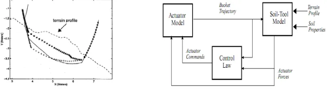
S. P. DiMaio, S. E. Salcudean, C. Reboulett, S. Tafazoli and K. Hashtrudi-Zaad, in 1998, a ground interaction-force model has been developed, which is based upon damping, stiffness, Coulomb friction and load forces. The environmental interaction forces are estimated for two different angles of attack, a, namely 10º and 40º; and similar bucket endpoint trajectories. Three of the four force components are computed relative to the bucket coordinate frame, which consists of normal, tangential, and orientation components, as shown in figure 3 [11]. O. Luengo and S. Singh in 1998 have developed a model of soil-tool interaction that predicts resistive forces experienced at the tool during digging. The predicted forces can be used to model the closed loop behavior of a controller that servos’ the joints of the excavator so as to fill the bucket. The new model was developed by reformulating version of the classical FEE which includes consideration of the terrain slope (α) during the excavation which is previously unaccounted phenomena in the interaction of an excavator bucket as it moves through soil as shown in figure 4 [12] [14].
Fig. 5 Actual versus predicted path of the bucket tip during digging. Fig. 6 Composite model of the digging process
computes the failure force based on the concept of the active and passive earth pressures. The failure force is computed as:
F = Fp - FA … (3) Where, FPand FA are the resulting passive force and the active force respectively [21].
Xiangwu (David) Zeng, Louis Burnoski, Juan, H. Agui and Allen Wilkinson, in 2007 have developed an analytical model based on principles of soil mechanics which is relatively simple to apply and accurately predicting the excavation force that will be encountered by digging tools on the lunar surface.
Fig. 7 Excavation blade and soil body at failure Fig. 8 Forces act on the blade
The model to calculate excavation force is shown in figure 7. The free-body diagram of the blade is shown in figure 8. The influence of important parameters on the excavation force is investigated and the results are compared with that predicted by other available theories. Parametric study shows that excavation force calculated by this model is more sensitive to cohesion of the regolith, which may help to explain the high value of excavation forced measured in past mission to the moon [24].
3.2. Soil-tool Models for Soil Properties
Xin Li and J. Michael Moshell in 1993, Analytic methods based on soil properties and Newtonian physics are presented to model soil slippage and soil manipulations and analyze the interaction between the soil mass and a bulldozer's blade. The analysis shows that the total upward force is always positive. That is, the soil mass being cut always moves upward along the blade. This phenomenon is also observed experimentally. These methods can be used to calculate the evolution of a given soil configuration under the constraint of volume conservation and to simulate excavating activities such as digging, cutting, piling, carrying or dumping soil [6].
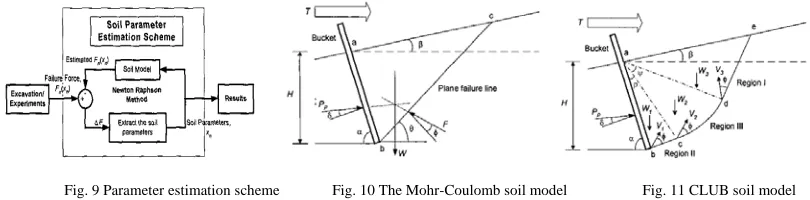
Fig. 9 Parameter estimation scheme Fig. 10 The Mohr-Coulomb soil model Fig. 11 CLUB soil model
Fig. 12 Tele-operated excavator vehicle Fig. 13 Hybrid soil model Fig. 14 The soil parameter estimation scheme
Choopar Tan, Yahya H Zweiri, Kaspar Althoefer and Lakmal D Seneiiratne in April 2004 have presented a novel method for estimating soil parameters for tele-operated excavator vehicle of figure 12 by using a hybrid soil model and the Newton Raphson method. The CLUB soil model (Hybrid soil model) shown in figure 13 is employed in the estimation scheme to model the failure force and the parametric optimization carried out by minimizing the error of the failure forces. A tool angle of 80º is chosen as the 'switching point' because the Mohr- Coulomb soil model has a very crude model accuracy for a tool angle higher than 80º whereas the CLUB soil model can provide a more accurate approximation compared to the Mohr-Coulomb soil model. The switching of the Mohr- Coulomb soil model at tool angle lower than 80º avoid the lengthy optimization in the CLUB soil model and it allows a real time parametric identification. This research demonstrates that the given method is capable of identifying the unknown soil parameters with a high degree of estimation accuracy matching measured and experimental data. In addition, the test shows the Newton Raphson method is highly robust compared to the least square method [19]. ChooPar Tan, Yahya H Zweiri, Kaspar Althoefer and Lakmal D Seneviratne, in April 2005 presented a method for identifying multiple unknown soil parameters in real-time using the novel Modified Newton Raphson Method for crawler type loader. The new approach involving a model selection strategy based on Parallel Execution Model, Flexible Parallel Execution Model and Hybrid Execution Model (HEM) is examined. This estimation method as shown in figure 14, works by incrementally improving the initial guess until the difference between the measured failure force and the modeled failure force is minimized and hence the soil parameters are identified. HEM proved to be a better technique to select the soil model in the estimation scheme with accurate estimation in short time [21].
3.3. Soil-tool Models for Soil failure
P. N. Wheeler and R. J. Godwin, in 1996, A force prediction model developed for single and multiple tines at speeds in which inertial effects are significant. The soil worked by the tines is assumed to obey the Mohr – Coulomb criterion. They have used the model of Godwin as a basis to predict the forces on single tines as shown in figure 15. To allow force predictions for multiple tines, the single tine model was adapted by Godwin to include tine interaction effects. This involved a model where the draught forces of the individual tines were added together, with compensation made for the area of overlap shown shaded in figure 16. Results of experiments carried out between speeds of 1 and 20 km / h are reported for both frictional (laboratory) and cohesive (field) soils and comparisons are made between theoretical and measured values.
Fig.15 Wide tine showing soil failure plane Fig. 16 Front view of triple tine arrangement showing imaginary tines
cutting. Comprehensive tests were carried out on sandy loam, clay loam and cemented sand soils using a glass-sided box apparatus and five model plane blades of rake angles 25º, 40º, 55 º, 70 º and 90 º, respectively.
Fig. 17 A schematic illustration of typical failure patterns in soil cutting: (a) shear failure; (b) crescent failure and lateral failure; (c) tensile failure. z: blade working depth; dc: critical depth.
Cutting forces were measured and soil deformation patterns were studied using a bead tracer technique as shown in figure 17. The failure characteristics of brittle fracture are shown to be quite different from those of shear failure. The results further show that transitions between these two modes of failure do occur and are governed by certain soil and implement factors, namely blade rake angle, soil strength and soil-blade interface condition. These factors should provide a basis for the reliable prediction of the failure type, and hence the quality of soil tilth expected in two-dimensional soil cutting operations [16].
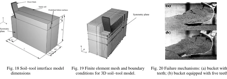
Fig. 18 Soil–tool interface model Fig. 19 Finite element mesh and boundary Fig. 20 Failure mechanisms: (a) bucket without dimensions conditions for 3D soil–tool model. teeth; (b) bucket equipped with five teeth.
continuously measures displacement, velocity and energy online during the movement of a test-rig manipulator with an attached bucket through different types of soils. A “non linear algorithm” is developed by them with an acceptable margin of error, this leads to a robust on-line soil-type identification and classification approach based on experimental data in real environments with unpredictable soil conditions. The algorithm works in real-time and is fast enough for implementation in a low-level controller [23].Fiorenzo Malaguti in 2009 presented a work on the periodic outline of soil cutting force and its dependence on cutting depth. It considers this phenomenon by 2D and 3D classical soil cutting models (McKyes’s model) with single and double wedge and it demonstrates that the distance between consecutive clod rupture surfaces depends on cutting depth and cutting angle too. This analysis shows important theoretical aspect of soil mechanics, but it focused and oriented on automated digging processes and to sense on go the parameters of agricultural terrain [25]. Daniel Dopico, Alberto Luaces and Manuel González, in 2010, the detailed simulation of bucket filling requires models to predict the material flow, a simplified bucket filling model has been developed for real-time purposes. During the excavation process, the bucket penetrates the removable terrain mesh originating viscous contact forces [26].
2. Conclusion
Here a review carried out on soil-tool interaction is divided in three different parts namely soil-tool model for resistive forces and trajectory planning, soil-tool model for soil properties and soil-tool model for soil failure. In the first part of review, A soil-tool interaction model developed by O. Luengo and S. Singh that predicts resistive forces experienced at the tool during digging. This new model is reformulating version of the classical FEE which includes consideration of the terrain slope (α) during the excavation which is previously unaccounted phenomena in the interaction of an excavator bucket as it moves through soil and the predicted forces can be used to model the closed loop behavior of a controller that servos’ the joints of the excavator so as to fill the bucket and also utilize for generation of tool trajectory. This new model gives better results for prediction of the resistive forces. In the second part of review, a novel method for estimating soil parameters for Tele-operated excavator vehicle is given by Choopar Tan, Yahya H Zweiri, Kaspar Althoefer and Lakmal D Seneiiratne. In their study they have proved that the Newton Raphson method is highly robust compared to the least square method. CLUB soil model (Hybrid Soil Model) is technically a very powerful approach to estimate the soil parameter, very promising and highly suitable for the soil-tool interaction identification of an autonomous excavator in an unpredictable, dynamical and potentially hazardous environment. In the third part of the review, the 3D finite element analysis is very powerful tool to simulate soil–blade interaction. Application of CFD in the area of tillage is anticipated to bring a new dimension to the tool design and study of soil behavior for different climatic conditions. Soil dynamic behavior using the CFD simulation will help in optimizing the design of tools with different shapes in order to reduce tool draft and energy demand over a wide speed range and to help modeling deferent types of soils based on their visco-plastic parameters.
“References”
[1] Nareshkumar N. Oza, “Finite Element Analysis and optimization of an Earthmoving Equipment Attachment – Backhoe” M. tech Dissertation Thesis, Nirma University, Institute of Technology, Ahmedabad, May 2006, pp. 5, 6.
[2] Peurifoy Robert L., Schexnayder J. Clifford, ”Construction, Planning, Equipment and Methods”, Tata McGraw hill publication, New Delhi, Sixth edition,2006, pp. 229-267.
[3] Off-Highway Research’s Multi-Client Study, “A detailed review on the Indian market for backhoe excavator”, October 2007. [4] By A. R. Reece, “The Fundamental Equation of Earth-Moving Machines”, Proc Instn. Mech. Engrs, Vol. 179, Pr 3F, 1964-65. [5] Sanjiv Singh, “An Operation Space Approach to Robotic Excavation”, Proceeding of the IEEE International Symposium on
intelligent control, Arlington, Virginia, U.S.A., 13- I5 August 1991.
[6] Xin Li and J. Michael Moshell, “Modeling Soil: Realtime Dynamic Models for Soil Slippage and Manipulation”, Institute for Simulation and Training University of Central Florida, 1993.
[7] B. A. Adams, D. Wulfsohn, and D. G. Frdlund, “Unsaturated Soil Mechanics for Agricultural Conditions”, International Summer Meeting Presentation, The American Society of Agricultural Engineers (ASAE), Hyatt Regency Crown Center, Kunsas City, Missouri, pp. 94-1037, 1994.
[8] A.M. Zein Eldin and Abdulrahman Al-Janobi, “Soil-Tillage Tool Interaction Analysis”, Misr Journal of Agricultural Engineering, Vol. 12 No. (3) July, 1995.
[9] Sanjiv Singh, “Learning to Predict Resistive Forces During Robotic Excavation”, Field Robotics Center, Carnegie Mellon University, Pittsburgh, 1995, PA 15213-3890.
[10] P. N. Wheeler and R. J. Godwin,” Soil Dynamics of Single and Multiple Tines at Speeds up to 20 km / h”, J . Agric. Engg. Res., 1996, V-63, pp. 243 – 250.
[11] S. P. DiMaio, S. E. Salcudean, C. Reboulett, S. Tafazoli and K. Hashtrudi-Zaad, “A Virtual Excavator Development and for Controller Evaluation”, Proceedings of the 1998 lEEE International Conference on Robotics & Automation Leuven, Belgium - May 1998.
[12] O. Luengo, S. Singh, “Modeling and Identification of Soil-tool Interaction in Automated Excavation”, Proceedings of the 1998 IEEURSJ, Intl. Conference on Intelligent Robots and Systems Victoria, B.C., Canada, October 1998.
[13] A.P. Onwualu and K.C. Watts, “Draught and vertical forces obtained from dynamic soil cutting by plane tillage tools”, Elsevier, Soil & Tillage Research, 1998, V-48, 239-253.
[15] Allan Ericsson and Jesper Slättengren, “A model for predicting digging forces when working in gravel or other granulated material”, 15th ADAMS European Users Conference, Rome 2000.
[16] O.B. Aluko and D.A. Seig, “An experimental investigation of the characteristics of and conditions for brittle fracture in two-dimensional soil cutting”, Elsevier, Soil and Tillage Research, 2000, V-57, pp. 143-157.
[17] Choopar Tan, Yahya H Zweiri, Kaspar Althoefer and Lakmal D Seneviratne, “On-line Soil Property Estimation for Autonomous Excavator Vehicles”, Proceedings of the IEEE International Conference on Robotics & Automation, Taipei, Taiwan, September 14-19, 2003. pp. 121-126.
[18] Mootaz Abo-Elnor, R. Hamilton and J.T. Boyle, “Simulation of soil–blade interaction for sandy soil using advanced 3D finite element analysis”, Elsevier, Soil and Tillage Research, 2004, V-75, pp. 61-73.
[19] Choopar Tan, Yahya H Zweiri, Kaspar Althoefer and Lakmal D Seneiiratne, “Hybrid Model in a Real-time Soil Parameter Identification Scheme for Autonomous Excavation”, Proceedings of the 2004 IEEE International Conference on Robotics 8 Automaton New Orleans, LA April 2004.
[20] J. Maciejewski, A. Jarzebowski, W. Trampczynski, “Study on the efficiency of the digging process using the model of excavator bucket”, Journal of Terramechanics V-40, 2004, pp. 221–233.
[21] ChooPar Tan, Yahya H Zweiri, Kaspar Althoefer and Lakmal D Seneviratne, “Online Soil-bucket Interaction Identification for Autonomous Excavation”, Proceedings of the 2005 IEEE International Conference on Robotics and Automation, Barcelona, Spain, April 2005.
[22] Subrata Karmakar, R. Lal Kushwaha, “Dynamic modeling of soil–tool interaction: An overview from a fluid flow perspective”, Journal of Terramechanics, V-43, 2006, pp. 411–425.
[23] S. M. Vahed, H. A. Delaimi, K. Althoefer, On-line Energy-based Method for Soil Estimation and Classification in Autonomous Excavation, Proceedings of the 2007 IEEE/RSJ International Conference on Intelligent Robots and Systems San Diego, CA, USA, Oct 29 - Nov 2, 2007.
[24] Xiangwu (David) Zeng, Louis Burnoski, Juan, H. Agui and Allen Wilkinson, “Calculation of Excavation Force for ISRU on Lunar Surface”, American Institute of Aeronautics and Astronautics, 2007.
[25] Fiorenzo Malaguti, “Classic Soil Cutting Models for Geomechatronics Applications”, 16th ISTVS Conference, Turin, Italy II.évf., 2009, No. IV. pp. 361-371.