Please cite this article as: M. Niaz Azari, Performance Improvement of a Slotted Solid Rotor Induction Motor with High Temperature Superconder Coating, International Journal of Engineering (IJE), IJE TRANSACTIONS B: Applications Vol. 32, No. 5, (May 2019) 693-700
International Journal of Engineering
J o u r n a l H o m e p a g e : w w w . i j e . i rPerformance Improvement of a Slotted Solid Rotor Induction Motor with High
Temperature Superconder Coating
M. Niaz Azari*
Department of Electrical Engineering, University of Science and Technology of Mazandaran, Behshahr, Iran
P A P E R I N F O
Paper history:
Received 21 Febraruary 2019 Received in revised form 4 April 2019 Accepted 05 April 2019
Keywords:
Bi-2223/Ag Super Conductor Critical Current
Slotted Solid Rotor Starting Torque
A B S T R A C T
This paper analyzes an induction motor with high temperature superconducter (HTS) coated slotted solid rotor. By slotting the solid rotor, the electromagnetic torque near synchronous speed will increase but the starting torque will decrease. To improve starting torque, rotor slots are coated with HTS materials. Using HTS material vary the rotor resistance to great extends in starting step and this means the starting torque will be maximized. Also the torque near synchronous speed will be higher than before because of the resistance of the HTS is completely zero in this period. This would help the torque become more than the case without any coating. It is concluded that, HTS coating of slotted solid rotor will increase the starting torque by 42 and 74% than smooth type rotor and slotted one, respectively. For case-study motor, the torque near synchronous speed these improvements were 75% and 33%, respectively. The performance of the proposed motor is simulated using finite element method (FEM).
doi: 10.5829/ije.2019.32.05b.11
1. INTRODUCTION1
Nowadays, induction motors are known as an extremely popular consumer in all industrial applications. These motors are cost effective and easy to maintain. Furthermore, self-starting is considered as a great advantage of these type. The resistance of rotor plays a vital role in the performance of squirrel cage induction motors including, starting torque and efficiency. A small amount of rotor resistance results in, a high efficiency at full load operation and a low amount of starting torque. On the other hand, a high starting torque and low efficiency at full load operation will be obtained as a result of a large rotor resistance [1–3]. In order to have a variable resistance in the rotor circuit, an external resistance is always needed. But, this issue is only applicable for the wound rotor induction motors. Thus, the major problem refers to immutability of resistance in the rotor of conventional squirrel cage motors which is made out of copper or aluminum.
It has been observed that, applying the solid rotor
*Corresponding Author Email: [email protected] (M. Niaz Azari)
instead of squirrel cage one is a great alternative in order to obtain the high load torque and improve the starting torque. Furthermore, the mentioned rotor has high mechanical robustness and manufacturing of that is cost effective. However, the use of solid rotor induction motor is restricted to specific applications due to two significant drawbacks including, low power density and low electrical conductivity compared to other alternatives [4].
conducted for various input voltages and the electrical equivalent circuit was used for analyzing the performances of the motor. The better starting and also accelerating torque of the HTS motor compared with the conventional one is resulted in as a great advantage of newly fabricated motor. Contribution by Song et al. [7], discussed about an experimental model of an induction motor which is immersed in liquid nitrogen bath with a superconducting secondary conductors, using Bi-2223/Ag HTS material. The mentioned test showed different results including; decrement in the resistance of the superconducting rotor with decreasing the slip and also achieving a better starting torque. Sekiguchi et al. [8], clarified the application of HTS Induction/Synchronous machines (HTS-ISM) in electrical vehicles. A 20 KW class of HTS-ISM is designed and also fabricated with DI-BSCCO superconductor. In accordance to the results, it is concluded that, the efficiency has greatly improved in the mentioned machine. But unfortunately, the steady state slip rotation was not considered. It should be noted that, the main contribution of this study is achieving a fully superconducting machine including an excellent synchronous rotation, containing a higher speed, for the first time in the world. Nakamura e al. [9] studied about design and also fabrication of the second generation of 20 KW class of HTS-ISM, which is used in the transportation equipment. The volume of the second generation HTS-ISM is reduced about 70% compared to the first class one. But the major principle of this paper is, the great enhancement of the torque and also the power density, simultaneously. BSCCO-2223, is applied as the HTS material in the rotor windings. It is noteworthy that, the system is cooled in the liquid nitrogen.
It is noted, some other investigations have focused on slotted solid rotor motor for the improvement of motor performance. As a result, Aho et al. [10] mentioned the higher are the saturation of magnetic flux density and electrical conductivity of the motor materials, the higher is the torque of motor. Therefore, the saturation of flux density and the electrical conductivity of the materials have direct relation with the torque of motor. Sharma et al. [11] aimed at maximizing the electromagnetic torque through depositing layers of Cu plus Fe-Co on the rotor surface. Other investigations indicated that, a better output torque and also a higher efficiency were considered as two significant advantages of a slotted solid rotor induction motor compared with a smooth one [12–14].
This study proposed deposition of a thin layer of HTS on the outer face of the solid rotor slots in order to improve the performance of the induction motor. Consequently, by means of the mentioned layer of HTS, the rotor resistance can have a great amount of incremental variation [15]. During the starting period of
induction motor, the slip of the motor is equal to one. As a result, two significant issues simultaneously occur. The first issue includes enormous induced current in the rotor core and the second one is the increased frequency of the rotor. The two important mentioned issues make HTS layer quench during the starting period. Consequently, a high starting torque can be achieved. But during the normal starting condition and after raising the speed and the torque of the motor, the HTS layer acts as a superconductor due to decrement of current and frequency of the rotor. After the perfect recovery of the HTS from quenching, the resistance of the solid rotor gets quite small due to zero resistance of the layer. In such situations, power loss in rotor circuit is minimum and only depends on some other factors including the rotor core and etc. As a result, a large current can be induced in the rotor circuit of the proposed motor at low levels of slip which leads to a high torque near the synchronous speed. It should be noted that, for a widespread range of load, the slip is equal to zero. Ultimately a real case-study motor with the proposed idea is simulated using finite element method. The obtained results confirmed the theoretical concepts.
2. PROPOSED SCHEME PRINCIPLE
The starting torque is always known as an important principle in the performance of induction motors. By the same token, solid rotor induction motors are widely used, because of their inherent characteristics, for improvement of the starting torque. On the other hand, a higher torque near the synchronous speed is always desirable. To this end, a slotted solid rotor is proposed. In fact, this type of rotor increases the penetration of the flux lines in the rotor core by means of the embedded slots. Thus, the existing volume for energy conversion will enhance compared to smooth solid rotor and consequently a high output torque in low slips is obtained [14, 16]. In other words, the electromagnetic torque in a solid rotor induction motor is generated due to interaction between the stator current and the eddy current, induced in the rotor. Therefore, in order to calculate the electromagnetic torque, the eddy current loss should be calculated at first. The mentioned loss is obtained by the following equation [17]:
= ∬| |
Induced region (1)
where and are the conductivity coefficient of the rotor and induced current density, respectively. By considering as the rotor angular velocity, the electromagnetic torque can be obtaind as follows:
It is concluded from Equation (1) that, the enhancement of the space at which the current is induced, causes the increment of the electromagnetic torque. It is worth noting that, a slotted rotor increases the flux density in the rotorBr. The electromagnetic torque
τ
, can bemaximized in low slips in accordance to the following equation.
(3)
where,
B
sis the stator flux density andk
is a constant which is defined as follows:(4)
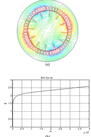
where , L, D, g and P, represent absolute permeability, axial length of the air gap, the diameter of the air gap, the length of the air gap and the number of poles, respectively. It should be noticed that, is the angle between the magnetic axis of the rotor and stator. As previously mentioned, penetration of the flux lines is increased in the rotor core by means of the embedded slots. Figure 1 shows this flux penetration in the slotted rotor and B-H curve of rotor material.
As previously mentioned, the starting torque is a significant principle which should always be considered, in performance of induction motors for various applications. Accordingly, applying the slotted rotor causes reduction of rotor electric resistance and also flowing a large amount of induced current in the rotor core which can eventually lead to a lower starting torque in slotted rotors compared to smooth types. In order to produce a high starting torque, a large starting resistance is required. On the other hand, during the normal accelerating condition the key point is minimization of power loss. To this end, a lower rotor resistance is always required during the normal accelerating period. As a result, a high electromagnetic torque is obtained in low levels of slip. The mentioned change in resistance, at the starting and also during normal operation of the motor leads to the best performance of an induction motor. In order to achieve the mentioned desirable performance, a thin layer of HTS is used on the slots surface. Hereby, the rotor resistance can vary as desired. As discussed before, the electric resistance should have its maximum value, at the start time. This issue is easily justified by the high current and frequency, applied to the rotor at this time. It should be noted that, in such circumstances, the layer of HTS is in quenching mode. But during the normal running period, the situation is different. In fact, the layer of HTS performs as a perfect conductor due to low current and also low frequency. Therefore, the resistance of the HTS will be equal to zero and the rotor resistance will be quite small. Consequently, the induction torque increases at low amounts of slip and a higher efficiency is obtained.
(a)
(b)
Figure 1. a) Flux penetration in the slotted rotor core; b) B-H curve of rotor material
To illustrate the above points, Figure 2 compares the torque-speed characteristics of a 4-pole, 50-Hz smooth solid-rotor and a slotted solid-rotor and also a HTS coated slotted solid-rotor induction motor. It can obviously be seen that, the HTS coated slotted motor produces a higher starting torque compared to other motors and the mentioned torque is really near the synchronous speed unlike others. As another amazing reality extracted from Figure 2, it could be said that, the synchronous torque, for a HTS coated slotted rotor, occurs at about 5 Nm in the synchronous speed.
Figure 2. Comparison of torque-speed characteristics of a 4-pole, 50-Hz smooth solid-rotor with the slotted solid-rotor and HTS coated slotted solid- rotor induction motor
kBs Br
τ
= ×0 2 2
P gDL
k π sinα
µ
3. FINITE ELEMENT ANALYSIS
A 2-D finite-element package is used to simulate the solid rotor induction motor. A time stepping finite element method is also needed in order to solve the magnetic field because of the non-linearity of rotor material and also the movement of the rotor. The calculation is based on solution of the magnetic vector potential A [4].
The curl of magnetic vector potential is equal to the magnetic flux density B, as in the following equation:
(5) On the other hand, the divergence of the magnetic vector potential is equal to zero as follows:
(6) The following equation can be obtained by substituting the magnetic vector potential definition in the induction law:
(7) As a result, the electric field equation can be written as follows:
(8) where, E and are the electric field strength and the electric scalar potential, respectively.
The eddy current density in the conducting zone can be stated as follows:
(9) where,
σ
represents the electric conductivity and E was already defined in Equation (8). The governing equation can be written in accordance to Ampere’s law and magnetic vector potential as follows:(10)
where,
µ
is the magnetic permeability.It is worth mentioning that, the induction torque is produced by an interaction between stator current of voltage source and the eddy current induced, in rotor. By assuming H and V as the magnetic field intensity and the volume, respectively. The related equation to the output torqueToutwith angular displacement θ, can be displayed as follows:
(11)
3. 1. HTS Material Modeling The nonlinear
characteristics of the HTS material can be expressed as follows [18]: n c c J E E J = ur (12)
where urE is the electrical field and urJ represent the current density vectors of the HTS. Furthermore,Ec,
c
J and nare the critical electrical field, critical current density and exponential factor of the HTS material, respectively.
The Kim–Anderson model, is known as a significant model in order to introduce the HTS resistivity
ρ
, which is expressed as follows [19]:(13)
where ρ0 is the additional resistivity, and variables which are dependent to the magnetic flux densityB, are evaluated by the following equations:
(14)
(15)
where J ,c0 B0and n0are the reference values of the critical current density, the magnetic flux and the exponent factor, respectively [20].
4. CASE STUDY SPECIFICATIONS
4. 1. Specifications of the StudiedMotor In this study, a 1.05 kW solid rotor induction motor which was previously designed and fabricated by Sharma et al. [11] which is taken as a real case study. In the mentioned motor, the stator and complete scale are the same. But the difference is that, the slots of the solid rotor are coated with HTS material. The input voltage has a value of 250 volts and the starting and the normal current values are 15 and 3.7 A, respectively. The complete data of the motor is described in Table 1. It should be noted that, the fabricated axially slotted solid rotor reported in literature [16] as shown in Figure 3.
4. 2. Specifications of the HTS Material Figure 4 shows a cross section shape, related to the placement of the HTS material layer in the rotor slots. It should be noticed that, the magnetic flux density of the studied motor, both in starting and steady state condition, considering the HTS material in rotor slots are also
A B ∇ × = 0 A ∇ ⋅ =
0
A
∇ ⋅ =
A E t ∂ ∇× = −∇× ∂ A E t ∂ ∇ × = −∇ × ∂ A E t φ ∂ = − − ∇ ∂ e A J E tσ σ∂ σ φ
= = − − ∇
∂
1
( A) Je
µ ∇ × ∇ × = 0 H out V T BdHdV θ ∂ = ∂
∫ ∫
0 ( ) 1 n n B B B = + 0 ( ) 1 0 Jc J BcB B =
+
1
( ) 1 ( )
( ) 0
( , )
( ) n B n B
c n B
c
E
E B E
J B
ρ ρ
−
TABLE 1. Data of the case study motor
Stator
Outer diameter 176 mm
Inner diameter 115 mm Stack length 46.5 mm
Number of slots 48 Conductor per slot 70
Slot depth 11.5 mm
Rotor
Outer diameter 114 mm Number of slots 12
Inertia (Jr) 0.642
(a)
(b)
Figure 3. a) Fabricated slotted solid rotor b) Exprimental Set-up [16]
Figure 4. Part of cross section of the case study motor with HTS layer on the rotor slot surface
shown in Figures 5(a) and 5(b), respectively. In these figures the steady state operation regards to synchronous speed situation.
The operation of all types of HTS materials are restricted within three significant parameters including; critical temperature, current density and magnetic field [21], as shown in Figure 6.
(a)
(b)
Figure 5. Magnetic flux distribution of the new motor at a) Starting condition; b) Steady state operation
Figure 6. Superconductivity in a 3D space defined by current density, temperature and magnetic field [20]
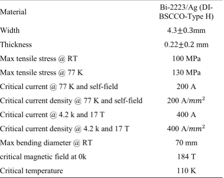
It should be noted that, the HTS material can be reverted to its normal condition (no superconductivity exhibition), if any of the three mentioned restrictions is exceeded. Therefore, the complete specifications of the applied HTS material layer which are given in Table 2, [21, 22] seem to be essential. It should be noted that, the operating temperature of the specified HTS material is at 77K which is known as the liquid nitrogen temperature.
TABLE 2. Specifications of the HTS material layer
Material BSCCO-Type H) Bi-2223/Ag
(DI-Width 4.3 0.3mm
Thickness 0.22 0.2 mm
Max tensile stress @ RT 100 MPa Max tensile stress @ 77 K 130 MPa Critical current @ 77 K and self-field 200 A Critical current density @ 77 K and self-field 200 A/ Critical current @ 4.2 k and 17 T 400 A Critical current density @ 4.2 k and 17 T 400 A/ Max bending diameter @ RT 70 mm critical magnetic field at 0k 184 T Critical temperature 110 K
The superconductors always exclude the magnetic fields, until their critical magnetic field is exceeded by the specified magnetic field. The critical field is defined at 0k and is equal to zero at critical temperature. Thus, the enhancement of the temperature leads to decrement of the critical magnetic field. The relation of the critical magnetic field at any arbitrary temperature below the critical temperature can be expressed as follows [23]:
(16)
where 0! and " are the critical magnetic field at 0k and critical temperature of the applied superconductor, respectively; which were already given in Table 2. Parameter T, represents the arbitrary temperature at which, the critical magnetic field is obtained.
4. 3. Critical Current Determination The critical current of the HTS layer is always considered as a determinative factor for a proper resistance adjustment of the slotted solid rotor in both starting and normal running condition of the motor. The measured critical current in Table 2, is obtained by using a standard four point configuration at liquid nitrogen [24]. It should be noted that, the voltage criterion is approximated to be 1 µV/cm.
The external perpendicular magnetic field dependence of the critical current has been evaluated at different temperatures, ranging from 4.2 K to 90 K [25], as shown in Figure 7.
As a result, a large amount of critical current prevents the quenching of HTS material during the starting time. On the other side, by considering a small amount of critical current, the recovery of the HTS material from quenching will never occur in normal running operation. Critical current of HTS layer was 200 A at 77 k and self-field.
Figure 7. Critical current in presence of external field at different temperatures [24]
5. SIMULATION ESULTS AND DISCUSSIONS
All the simulation was done by the simulation software Ansoft Maxwell 10. Figure 8 has depicted the speed versus time charecterstic in order to illustrate the capabilty of the HTS coated induction motor. As it can be clearly seen in Figure 8, the induction motor can amazingly reach to synchronous speed under the load torque of 5 Nm and also rotor moment of inertia, Jr, whereas, the un-coated slotted motor works with approximate slip of 3% in the same situation. As previously mentioned, in such circumstances the motor can easily reach to synchronous speed because of two important reasons including low resistance of HTS deposited rotor near the synchronous speed and also the existence of the electromagnetic torque in this speed.
Figure 9 also shows that under load torque of 5 Nm and five times of rotor inertia, the proposed motor reaches to synchronous speed after longer period of time compared to the previous situation. In this term, the slotted solid rotor runs at the slip of 6%.
Finally, in order to achieve a better approval for the capability of the new proposed method, another simulation is conducted. The results of the mentioned simulation, shown in Figure 10 demonstrate that, for
Figure 8. Comparison between speed-time responses of un-coated slotted solid and HTS un-coated slotted rotor motor for 5 Nm load torque and rotor moment of inertia
( )
0 1 2c c
c T B B
T
≈ −
Figure 9. Comparison between speed-time responses of un-coated slotted solid and HTS un-coated slotted rotor motor for 5 Nm load torque and 5*Jr
Figure 10. Comparison between speed-time responses of un-coated slotted solid and HTS un-coated slotted rotor motor for 6 Nm load torque and rotor moment of inertia
inertia of the rotor and under constant 6 Nm load torque, HTS slotted solid-rotor motor works at low slip of 2.3 % whereas, the usual slotted one will oscillate with a high slip of 16%.
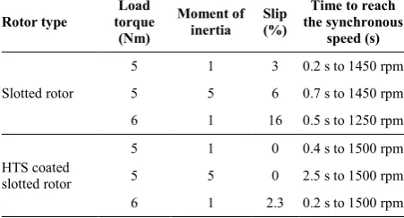
The approximate performance improvement values of different rotor structures with various load torques and moment of inertia are given in Table 3.
As a result of the simulations, it is concluded that, coating the slotted solid rotor with HTS materials causes
TABLE 3. Performance improvement of induction motor with different types of rotor
Rotor type torque Load (Nm)
Moment of inertia Slip (%)
Time to reach the synchronous
speed (s)
Slotted rotor
5 1 3 0.2 s to 1450 rpm 5 5 6 0.7 s to 1450 rpm 6 1 16 0.5 s to 1250 rpm
HTS coated slotted rotor
5 1 0 0.4 s to 1500 rpm 5 5 0 2.5 s to 1500 rpm 6 1 2.3 0.2 s to 1500 rpm
an increment in starting torque, which is approximated to be 42 and 74% than smooth type rotor and slotted one respectively. For the case-study motor, the torque near synchronous speed these improvement were 75 and 33% respectively.
6. CONCLUSION
In this paper, finite element method was implemented to analyze a new structure of induction motor with HTS-coated axially slotted solid rotor. For simulation a real case study is selected. It was confirmed, the speed of the HTS coated motors maintained synchronous speed up to 5 Nm constant load torque. The torque value is not achieved more than 1.7 times of the common slotted solid rotor motor. These promising properties were obtained by using of the resistance variation of the HTS material which was used as coating of slots of the solid rotor. It was concluded that the HTS coated slotted solid motor showed better performance than that of the non-coated one.
7. REFERENCES
1. Hassanpour Isfahani, A., and Vaez-Zadeh, S., “Line start permanent magnet synchronous motors: Challenges and opportunities”, Energy, Vol. 34, No. 11, (2009), 1755–1763. 2. Marcic, T., Stumberger, G., Stumberger, B., Hadziselimovic,
M., and Virtic P., “Determining Parameters of a Line-Start Interior Permanent Magnet Synchronous Motor Model by the Differential Evolution”, IEEE Transactions on Magnetics, Vol. 44, No. 11, (2008), 4385–4388.
3. Yektaniroumand, T., Azari, M. N., and Gholami, M., “Optimal Rotor Fault Detection in Induction Motor Using Particle-Swarm Optimization Optimized Neural Network”, International Journal of Engineering - Transactions B: Applications, Vol. 31, No. 11, (2018), 1876–1882.
4. Aho, T., “Electromagnetic Design of a Solid Steel Rotor Motor for Demanding Environments”, Doctoral dissertation, University of Technology, Lappeenranta, Finland, 2007. 5. Sim, J., Park, M., Lim, H., Cha, G., Ji, J., and Lee, J., “Test of
an induction motor with HTS wire at end ring and bars”, IEEE Transactions on Appiled Superconductivity, Vol. 13, No. 2, (2003), 2231–2234.
6. Nakamura, T., Miyake, H., Ogama, Y., Morita, G., Muta, I., and Hoshino, T., “Fabrication and Characteristics of HTS Induction Motor by the Use of Bi-2223/Ag Squirrel-Cage Rotor”, IEEE Transactions on Applied Superconductivity, Vol. 16, No. 2, (2006), 1469–1472.
7. Song, T., Ninomiya, A., and Ishigohka, T., “Experimental Study on Induction Motor With Superconducting Secondary Conductors”, IEEE Transactions on Applied Superconductivity, Vol. 17, No. 2, (2007), 1611–1614. 8. Sekiguchi, D., Nakamura, T., Misawa, S., Kitano, H., Matsuo,
9. Nakamura, T., Itoh, Y., Yoshikawa, M., Nishimura, T., Ogasa, T., Amemiya, N., Ohashi, Y., Fukui, S., and Furuse, M., “Tremendous Enhancement of Torque Density in HTS Induction/Synchronous Machine for Transportation Equipments”, IEEE Transactions on Applied Superconductivity, Vol. 25, No. 3, (2015), Article No. 5202304. 10. Aho, T., Sihvo, V., Nerg, J., and Pyrhonen, J., “Rotor Materials
for Medium-Speed Solid-Rotor Induction Motors”, In IEEE International Electric Machines & Drives Conference, IEEE, (2007), 525–530.
11. Sharma, N. D., Anbarasu, R., Nataraj, J., Dangore, A., and Bhattacharjee, B., “Experimental investigations on high speed solid and composite rotor induction motor”, In Proceedings of International Conference on Power Electronics, Drives and Energy Systems for Industrial Growth, Vol. 2, (1996), 913–919. 12. Pyrhonen, J., Nerg, J., Kurronen, P., and Lauber, U.,
“High-Speed High-Output Solid-Rotor Induction-Motor Technology for Gas Compression”, IEEE Transactions on Industrial Electronics, Vol. 57, No. 1, (2010), 272–280.
13. Ho, S. L., Niu, S., and Fu, W. N., “A Novel Solid-Rotor Induction Motor With Skewed Slits in Radial and Axial Directions and Its Performance Analysis Using Finite Element Method”, IEEE Transactions on Applied Superconductivity, Vol. 20, No. 3, (2010), 1089–1092.
14. Niaz Azari, M., and Mirsalim, M., “Performance Analysis of a Line-start Permanent Magnet Motor with Slots on Solid Rotor Using Finite-element Method”, Electric Power Components and Systems, Vol. 41, No. 12, (2013), 1159–1172.
15. Sim, J., Lee, K., Cha, G., and Lee, J., “Development of a HTS Squirrel Cage Induction Motor With HTS Rotor Bars”, IEEE Transactions on Appiled Superconductivity, Vol. 14, No. 2, (2004), 916–919.
16. Niaz Azari, M., and Mirsalim, M., “Line-start permanent-magnet motor synchronisation capability improvement using slotted solid rotor”, IET Electric Power Applications, Vol. 7, No. 6, (2007), 462–469.
17. Canova, A. and Vusini, B., “Design of axial eddy-current couplers”, IEEE Transactions on Industry Applications, Vol. 39, No. 3, (2003), 725–733.
18. Nibbio, N., Stavrev, S., and Dutoit, B., “Finite element method simulation of AC loss in HTS tapes with B-dependent E-J power law”, IEEE Transactions on Appiled Superconductivity, Vol. 11, No. 1, (2001), 2631–2634.
19. Stavrev, S., Grilli, F., Dutoit, B., Nibbio, N., Vinot, E., Klutsch, I., Meunier, G., Tixador, P., Yang, Y., and Martinez, E., “Comparison of numerical methods for modeling of superconductors”, IEEE Transactions on Magnetics, Vol. 38, No. 2, (2002), 849–852.
20. Fukui, S., Ogawa, J., Sato, T., Tsukamoto, O., Kashima, N., and Nagaya, S., “Study of 10 MW-Class Wind Turbine Synchronous Generators With HTS Field Windings”, IEEE Transactions on Applied Superconductivity, Vol. 21, No. 3, (2011), 1151–1154.
21. Kalsi, S., Applications of high temperature superconductors to electric power equipment, John Wiley & Sons, Hoboken, New Jersey, (2011).
22. Choi, S., Kiyoshi, T., Matsumoto, S., Itoh, K., Hase, T., Zaitsu, K., Hamada, M., and Sugano, M., “The Characteristics of Bi-2223/Ag Conductor for High Field Application”, IEEE Transactions on Applied Superconductivity, Vol. 18, No. 2, (2008), 1159–1162.
23. Kachhava, C., Solid State Physics, Solid State Device And Electronics, New Age International, (2003).
24. van der Laan, D. C., Van eck, H., Haken, B., Schwartz, J., and Ten Kate, H., “Temperature and magnetic field dependence of the critical current of Bi/sub 2/Sr/sub 2/Ca/sub 2/Cu/sub 3/O/sub x/ tape conductors”, IEEE Transactions on Appiled Superconductivity, Vol. 11, No. 1, (2001), 3345–3348. 25. Yusefi, A., and Javadpour, J., “Effect of Sintering Conditions on
Microstructure and the Superconducting Properties of YBa2Cu3O7 x”, International Journal of Engineering - Transactions B: Applications, Vol. 16, No. 4, (2003), 355–360.
Performance Improvement of a Slotted Solid Rotor Induction Motor with High
Temperature Superconder Coating
M. Niaz Azari
Department of Electrical Engineering, University of Science and Technology of Mazandaran, Behshahr, Iran
P A P E R I N F O
Paper history:
Received 21 Febraruary 2019 Received in revised form 4 April 2019 Accepted 05 April 2019
Keywords:
Bi-2223/Ag Super Conductor Critical Current
Slotted Solid Rotor Starting Torque HTS .
!" # $% & ' ( ') #! *+ , $% . $% ./ -, .
') 0+ , * 12 ') , $% . - 12 ' $% ( #! *+ ' ') , * * 5 6 . 78 , . $% 9 : ;# 42 8 74 ') 8 , !34- . ' $% ( #! : ;# 75 8 33 8 4
#A4+ .
B /!$ '2 B 7
. C
* ) % D .
doi: 10.5829/ije.2019.32.05b.11
![Figure 3. a) Fabricated slotted solid rotor b) Exprimental Set-up [16]](https://thumb-us.123doks.com/thumbv2/123dok_us/19597.2002066/5.595.94.246.491.610/figure-fabricated-slotted-solid-rotor-b-exprimental-set.webp)