Design of a Fuzzy Controller Chip with New Structure,
Supporting Rational-Powered Membership Functions
A. Naderii ٭, H. Ghasemzadehii, A. Pourazarii and M. Aliasgharyii
Microelectronic Research Labratory of Urmia University
i * Corresponding Author, A. Naderi is with the Department of Electronic Engineering, urmia University, Urmia, Iran (e-mail: [email protected]).
ii H. Ghasemzadeh, A. Pourazar and M. Aliasghary are with the Department of Electronic Engineering, urmia University, Urmia, Iran (e-mail: [email protected], [email protected], [email protected] ).
ABSTRACT
In this paper, a new structure possessing the advantages of low-power consumption, less hardware and high-speed is proposed for fuzzy controller. The maximum output delay for general fuzzy logic controllers (FLC) is about 86 ns corresponding to 11.63 MFLIPS (fuzzy logic inference per second) while this amount of the delay in the designed fuzzy controller becomes 52ns that corresponds to 19.23 MFLIPS. This mixed analog/digital realization of the circuit makes the design programmable and extendable. The proposed controller supports Rational-Power Membership Functions with a resolution of 0.03125. Simulation results of the controller using HSPICE simulator level 49 in 0.35um in CMOS process technology (BSIM3v3) show an average power consumption of 4.38mW, and an RMS error of 1.26%. This controller can be used in many applications in which there is a need for a controller chip by correct programming with system experts. Meanwhile the whole area of the chip is 0.0775mm2.
KEYWORDS
Fuzzy controller, Rational-powered membership function, CMOS, Low power.
1. INTRODUCTION
Nowadays, fuzzy logic controllers are used in industry widely and there are many ICs in CMOS process which are based on fuzzy logic. Inputs of fuzzy controllers consist of member membership functions with different configurations. For practical applications, the inputs are indeed normalized by these functions and go through fuzzy controllers as variables. In recent years, structures used in FLCs has not changed and usually it has been used from a general structure to control technical systems, while by specialization of control in special applications it can be improved in the performance parameters.
In [1], the Rational-Powered Membership Functions (RPMF) are discussed and optimized using Extended Kalman Filter (EKF) algorithm. These functions are the general forms of triangular/trapezoidal forms and also those functions which are generated by applying Linguistic Hedges (LH). Fig. 1 shows typical shapes of these functions. The triangular membership function has two straight lines, but the rational-powered membership functions are composed of two curves. According to Fig.
Figure 1: Rational-powered membership functions
1 and (1), the ith RPMF requires five parameters to be
determined: modal point (ci), upper half width (bi+) and its
power (ai
+), lower half width (
bi
-) and its power (
ai -). The
special case is when ai+=aj-=1; in this case the curves are
reduced to straight lines and the membership functions are triangular. Mathematically, the ith rational-powered
membership function of the jthinput is modeled as:
ij
ij
(1 ) if c
( ) (1 ) if c
0 otherwise
ij
ij
a
j ij
ij j ij
ij a
j ij
ij j j ij ij
ij
x c
b x c
b
x c
f x x c b
b
−
+
− −
+ +
−
⎧ + − ≤ ≤
⎪ ⎪
⎪ −
⎪
=⎨ − ≤ ≤ +
⎪ ⎪ ⎪ ⎪⎩
(1)
powers which are used in Linguistic Hedges Fuzzy Logic Controller (LHFLC) are generated by this structure for both upper and lower half width powers (ai+ = aj- = a)
with common values of: “a = 0.25, 0.5, 0.75, 1.25, 1.5,
1.75, 2 and 4” corresponding to hedges: “slightly, less, minus, plus, more, much more, very, and absolutely (very very)”, respectively. In addition, [3] proposed another architecture which can generate RPMFs using two main blocks from the power 0.125 to 4 with the resolution of 0.125 and by using 15 programming codes. The Main problem of these designs besides their complicate structure and more hardware is their limitation in generating desired powers. In our structure these problems are resolved and consequently powers from 0 to 4 are accessible with a higher accuracy and a resolution of 0.03125, only by 8 programming codes.
2. STRUCTURE OF FUZZY LOGIC CONTROLLERS
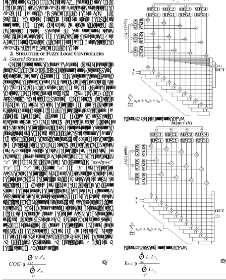
A. General Structure
General structure of fuzzy FLC used in recent articles is shown in Fig. 2 [3], [5]. In this structure, it is supposed that there are two inputs and one output. First input of fuzzifire consist of four membership functions with labels of low, medium, high, very high and second input consist of three memberships that labeled low, medium, high. Supporting of rational powered membership functions depends on type of the controller and its objectives. Although using this block in controllers is voluntary, by flexible normalized inputs and ability of supporting various types of membership functions with different shapes, the controller will have better results. Outputs of fuzzifires are connected to minimize operators two by two and the minimum of weights is selected. Number of rules is a multiplication of membership functions; hence there are 4×3 rules. Rules of the controller are considered as heart of a fuzzy system. These rules can be constant like
“c” or can be in linear form of inputs like “ax+by+c”
(“x” and “y” are inputs, “a” and “b” are constant).
Type of the controller depends upon the rules. If they are constant, hence controller will be zero-order type or singleton and if they are linear combinations of inputs plus a constant, the controller is known to be a first type or First-Order, obviously this type can be converted to the singleton; hence first-order is selected to have this ability. At the end of each fuzzy system there is a defuzzification block to defuzzify fuzzy contents. Type of defuzzifire selected in this paper is COG (center of gravity). It is a typical defuzzifire in fuzzy controllers, because it is simple in computation phase and is described easily according to (2). As shown in Fig. 2, we need 7 fuzzifire, 12 minimize operators, 12 multipliers, 1 divider, 2 collectors and 12 fuzzy rules.
1
1
n i y i i
n y i i
y C O G
µ µ =
=
=
∑
∑
(2)
B. The proposed Structure
The main change in the general structure is related to the defuzzfication block. This change is first described, and then will be used in the structure. The COG used in the current mode circuits of the fuzzy logic controller can be written as:
Figure 2: General structure of FLC
Figure 3: Proposed structure of FLC
1
1
i y i
y i n
y i
CO G n
i
I I I
I
µ
µ =
=
=
∑
∑
According to (2) it is needed to use three functions, adder, division and multiplication. We proposed a method that requires 2 functions, because division can be eliminated by considering the following two conditions.
1. Summation of weights is one, because of Membership functions sub normality.
2. Using multiplier in calculation of final value of weights instead of “minimizing” operator.
To clarify this, a simple example is explained.
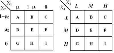
Consider a fuzzy controller with two inputs and one output, and each input consists of three membership functions with labels of “Low”, “Medium” and “High”
according to Fig. 4. Thus, we will have 32 rules. If the controller with three inputs of “xa” and “xb” is
considered, we will have weights according to Fig. 5. By calculation of the output using (2) and Fig. 5, we will have:
1 2 1 2 1 2 1 2
1 2 1 2 1 2 1 2
(1 ) (1 )(1 ) (1 )
(1 ) (1 )(1 ) (1 )
A B D E
COG µ µ µ µ µ µ µ µ
µ µ µ µ µ µ µ µ
− + − − + + −
=
− + − − + + −
(4)
Denominator of (4) is always unity; in other words by using the above conditions we can eliminate division from the difuzzifier part. Consequently (3) is changed to (5):
1
i y i n
y COG
i
I
I I
µ=
=
∑
(5)According to above statements the general structure in Fig. 2 can be simplified to the one shown in Fig. 3.
The advantage of the new structure is that the speed of a fuzzy controller is evaluated by speed of the defuzzifier block [6]. On the other hand, the divider circuit has a negative effect in the defuzzifier block; hence by eliminating the divider, the speed will increase as will be shown later in the simulation section.
Figure 4: Input membership functions
Figure 5: Rule based of the FLC
3. CIRCUIT DESIGNING OF FLC
In this part, required circuits for designing controller are analyzed. As shown in Fig. 3, they are:
1-A fuzzifire circuit with ability of generation of S, Z with triangle and trapezoid membership functions.
2-A genrator circuit of rational power consisting of squarer and square root circuits.
3-A two input-one output multiplier circuit. 4-Programmable circuits for rules.
A. Fuzzifier Circuit
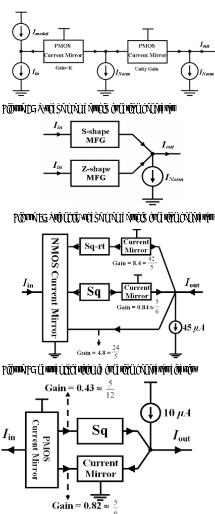
The generator of Z-shape membership function is shown in Fig. 5. Relationship between input-output current in circuit is given in (6), in which Inorm is a
constant current with the value of 10µA that normalized to one and Imodal characterizes the downfall point of
Z-shape. When Iin is bigger than IModal, the current mirror 1
that has variable gain (K) activates and subtracts K(IModal
-Iin) from INorm. This current then is applied to the current
mirror 2 which is the output current. Current mirror 1 does 2 operations: 1-identifying downward edge of Z-shape membership function, 2-giving the ability of changing slope of Z-shape membership function to the circuit with variable gain k. In fact, IModal and gain K are
programmable by user.
(
)
out Modal in Norm
I
=
K I
−
I
−
I
(6) To generate S-Shape membership function, we first use Z-shape circuit, then subtract it from INorm.For triangle, we connect S and Z to one node, and then subtract INorm from their sum. Obviously, trapezoid
membership function can be generated as discussed above.
Figure 7: S-shape membership function generator
Figure 8: Triangle -shape membership function generator
Figure 9: natural logarithmic function generator circuit
Figure 10: exponential function generator circuit
B. Rational power membership function generator circuit
Design of this circuit is done by circuits of exponential and logarithmic functions [7]. In fact, it should be designed a circuit in CMOS process to simulate the membership functions given in Fig. 1. For this purpose, triangle membership functions are applied as inputs to the circuit to receive math power from 0 to 4, as if power is less than 1; the membership function has convex parts and if it is more than 1, membership function has concave parts. Besides, for achieving high resolution we use a new
design. Suppose we name triangle membership function as “x” and math power as “a”, now by using logarithm
and exponential properties, we have: xa=exp(a ln x).
Major problem in this method is that there is not a proper circuit to implement them in CMOS process. The proposed method is to use approximation of these functions. Approximations that are obtained for math functions with MATLAB are:
|
ln x| ≈ -0.84 x2 + 4.8 x - 8.4 x+ 4.5(7)
e-x ≈ 0.19 x2 - 0.82 x + 1 ≈ (0.43x)2-0.82x+1 (8)
According to (7) and (8) for implementing these approximations 2 main circuits are used: squarer and square-rooter circuits which will be discussed below. Equations (7) and (8) are implemented in Fig. 9 and 10, respectively.
C. Squarer circuit
Fig. 11-c shows the current-mode squarer circuit based on the "dual translinear loop" [9]. Consider a loop of MOS transistor M1 to M4 (translinear loop), summing the
gate-source voltages around the loop gives:
4 3 2
1 GS GS GS
GS V V V
V + = + (9)
Assuming that MOS transistors M1 to M4 are biased in
the saturation region and all transistors are well matched and have long channel length, rewrite (9) as:
4 3 2
1 I I I
I + = + (10)
and KCL at nodes A and B as:
in out
3
I
I
I
=
+
(11)in out
4
I
I
I
=
−
(12) Considering I1=I2=IB and substituting (11) and (12) into(10) and squaring both sides twice, we have:
2 in 2 out 2 out out B 2
B 16I I 4I 4I 4I
I
16 − + = − (13)
The output current Iout becomes:
B B
2 in
out I
I 4 I
I = +
(14)
D. Square rooter circuit
Fig. 11-b shows the current-mode square rooter circuit [8]. This circuit is based on the "up-down topology translinear loop". Applying KVL for translinear loop
composed of NMOS transistors M1–M4 results in:
4 GS 2 GS 3 GS 1
GS V V V
V + = + (15)
a) b) c) Figure 11: a) Multiplier circuit b) Square rooter circuit c) Squarer circuit
2 ) V V ( L W ox C n 2 1
IDS = µ GS− t
(16) So (15) can be rewritten as:
4 2 3
1 I I I
I + = +
(17) Applying KCL in the output node gives:
2 I I I I
I2+ 4 = out + X + Y
(18) Finally, the input and output currents of NMOS current mirror satisfy the following equation:
2 Y X 4 Y
X I I I I I
I + + = + + (19)
This leads I2 = I4. Squaring (17) and using (18) and the
result of (19) give the desired relationship between the inputs and the output:
Y X out I I
I =
(20)
E. Implementation of constant coefficients
For implementing approximations in exponential and logarithmic functions, we need a circuit to implement constants coefficients. Since circuits are designed in current mode, with current mirrors that their gains are equal to their desired constants, it can be simply done.
F. Multiplier Circuit
The basic principle of the operation of the proposed multiplier is based on the following equation:
XY Y
X Y
X ) ( ) 4
( + 2− − 2= (21)
The analog multiplier circuit is shown in Fig. 11-a [9]. It is based on the squaring circuit of the Fig. 11-c and two dual translinear loops. First loop (M1 to M4) provides a (X+Y) input function to squarer function (X+Y) 2, the
second loop (M5 to M8) provides a X-Y input function to squarer function (X-Y) 2.
B B Y X O I I I I
I = + +
4 )
( 2
1 (22)
B B Y X O I I I I
I = − +
4 )
( 2
2 (23)
2
1 O
O
out I I
I = − (24)
Substituting (22) and (23) into (24) results in:
B Y X out I I I
I = (25)
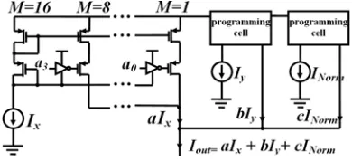
G. Programmable consequence rules
As we said, rules are functions of inputs. For a Takagi-Sugeno (TS) controller type one (first order), they are identified by the following phrase in the current-mode: IF Ix is Ax AND Iy is By THEN Iout = aIx + bIy + c
Since these rules should be programmed by system user according to its application, a structure is exhibited in Fig. 12 that can be programmed for different applications by ao-a3 switches. The inputs are in the current mode, thus
this structure is simply implemented by current mirrors with adjustable gains.
4. SIMULATION RESULTS
The block diagram in Fig. 3 has been simulated by HSpice. For the purpose of comparison, designed controller with ideal type, we compare simulation results of HSpice with fuzzy logic toolbox in MATLAB for 2 random inputs. Ideal output surface obtained by MATLAB is shown in Fig. 14 and output surface of HSpice is shown in Fig. 13 leading to 1.17% RMS error. By simulation in other edges RMS errors are obtained 1.27%, 1.38% and 1.21%. Thus, average error will be 1.26%.
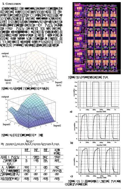
5. CONCLUSION
In this article, a new structure for fuzzy controllers has been proposed with an advantage of high speed and low power consumption. In Fig. 16 a pulse has been applied to each of the general and proposed structures. There was a 5pf load capacitance in the output. The delay time is 86ns for the first controller (it means 11.63 MFLIPS) as it is 52ns (19.23 MFLIPS) for second one (the proposed controller) that illustrates a remarkable optimization in comparison with other works. In table 1 this work is compared with others. This controller is designed in CMOS process and simulated with by HSpice and can be programmed by system expert in different applications.
Figure 13: Simulated control surface by Hspice
Figure 14: Ideal control surface by Matlab
TABLE 1
COMPARISION BETWEEN THIS WORK AND REPORTED WORKS
[3] [4] [5] This work
Speed (MFLIPS) - 15.87 5.26 19.23 Power cons.
(mW)
5 10.5 8.4 4.38
RMS error (%) 1.32 - 2.7 1.26 RPMF resolution 0.125 0 0 0.03125 Power supply (V) 3.3 3.3 3.3 3.3 Technology (um) 0.35 0.35 0.35 0.35
Figure 15: Layout of the proposed FLC
Figure 16: a) input pulse b) Proposed FLC response c) General FLC response
a)
b)
6. REFERENCES
[1] M. Mottaghi Kashtiban, A. Khoei, and Kh. Hadidi; “Optimization of Rational-Powered Membership Functions Using Extended Kalman Filter,” Journal of Fuzzy Sets and Systems (FSS), Elsevier, 159(23), 2007.
[2] C. Y.Chen, Y. T. Hsieh and B. D. Liu; “Circuit implementation of linguistic-hedge fuzzy logic cotroller in current-mode” IEEE Transaction on Fuzzy Systems, Vol. 11, pp.624-646, 2003. [3] M. Mottaghi Kashtiban, A. Khoei, and Kh. Hadidi; “A
Current-mode, First-Order Takagi-Sugeno-Kang FLC, Supporting Rational-Powered Membership Functions” IEICE TRANS. ELECTRON., Vol. E90-C, No.6 2007.
[4] R. Amirkhanzadeh, A. Khoei, Kh. Hadidi, “A mixed-signal current-mode fuzzy logic controller”, Int. Journal of Electronics and Communications, pp. 177-184, 2005.
[5] C. Dualibe, P. Jespers, and M. Verleysen; “A 5.26 MFLIPS programmable Analogue Fuzzy Logic Controller in a Standard CMOS 2.4µ Technology”, ISCAS, pp. 377-380, May 2000.
[6] Y.Chen, Y.Huang, D.Liu; “Current-mode defuzzifier circuit to realise the centroid strategy“, IEE Proc.-Circuits Devices Syst., vol. 144, No. 5, Octobr 1997.
[7] A. Naderi, A. Khoei, Kh. Hadidi, "High resolution RPMF using logarithmic and exponential approximation in CMOS technology," 16th International Conf. on Electrical Engineering, (ICEE) Tehran, Iran, 248 – 254, 2008.
[8] A. j. Lopez-martin and A. Carlosena; “Current-Mode Multiplier/Divider Circuits Based on the MOS Translinear Principle,” Analog Integrated Circuits and Signal Processing, pp. 265-278, 2001.