International Journal of Industrial Electronics, Control and Optimization .
© 2019 IECO
….
Vol. 2, No. 3, pp. 221-232, July (2019)Secondary Voltage Control in a Hybrid Microgrid
Yousefreza Jafarian
1,†, Amin Karimi
2, and Hassan Bevrani
31,2,3
Smart/Micro Grids Research Center, University of Kurdistan, Sanandaj, Iran
Compared to individual DC or AC microgrids, Hybrid Microgrids (HMGs) are more efficient and inexpensive due to the elimination of multiple DC-AC-DC conversions. In HMGs, where AC loads are supplied by a DC link, load demand disturbance has direct negative effects on the DC link voltage. In this study, primary and secondary controllers are applied to realize suitable operation conditions and control the microgrid converters. Each converter has a primary controller to compensate for the demand power fluctuations. A secondary controller is also designed for extra demand varieties to send the proper control signals to the primary controllers. The expressed capability of the primary controllers can be obtained by designing a simple and robust secondary controller. Hence, the effects of demand fluctuations are eliminated and the system is stabilized. The overall state space model of the system is conducted for stability analysis. To demonstrate the proposed controller efficiency, a prototype HMG is modeled and simulated. The stability analysis reveals that the system is stable when the secondary controller tracks the error signal of the DC link. Simulation results show that the proposed method could efficiently manage the AC side voltage under load fluctuations.
Article Info
Keywords:
Boost chopper; DC link voltage; Inverter; Rectifier; State space modeling.
Article History:
Received 2018-09-18 Accepted 2019-01-20
I.
I
NTRODUCTIONIn recent years, scientists have focused on using renewable sources due to the depletion of fossil fuels and the environmental pollution. In addition, demand for electric power as a clean and efficient type of energy has significantly increased [1–3]. As the consumption of the electric power goes up, the robust management of the electrical distribution system becomes more essential for increasing the stability and efficiency of the grid. Among various systems and techniques, microgrid (MG) is a new and efficient system for the management of the widespread grid. Indeed, this system consists of a block of smart grid in which distributed energy sources (DESs) are widely used to supply required electric power [4–7]. These small-scale systems have many advantages such as reducing environmental pollutions, decreasing electric energy cost, increasing the stability of power systems, and improving the quality of electric power [8–10].
MGs can operate in two operating modes: autonomous and
grid-connected operation modes. The ability to switch between these two operating modes considerably improves the stability and reliability for consumers and power system operators. Generally, MGs are classified in three categories: alternative current (AC), direct current (DC), and hybrid AC-DC [11–13]. While DC MGs can be linked to DC output sources (e.g., PVs and energy storage systems) and support DC electronic loads with less conversion and loss, they do not deal with some challenges in AC MGs such as synchronization, frequency control, and reactive power management [14–17].
Hybrid microgrids (HMGs) have been subject to extensive research in the literature recently [18,19]. HMGs consist of both AC and DC networks with various topologies [1,15,17,20,21] while the advantages of both systems are preserved. MGs are connected to electrical grid via point of common coupling (PCC) by static switches (SS).
In order to secure operation, different control loops are used, and they are classified into four levels: local, secondary, emergency/central and global control. Local control is a decentralized control with the lowest control level in MG. Voltage and current control loops for small generators or controllable loads are known as good samples for this type. If a
†Corresponding Author: [email protected], [email protected] Tel: +98-9112100208, Kurdistan University, Iran.
*
Department of Electrical and Computer Engineering, University of Kurdistan, Sanandaj, Iran.
A
B
S
T
R
A
C
disturbance happens out of the operational range of the local control loop, a secondary control loop is applied to adjust several micro-sources or controllable loads. Thus, the system operational indexes are kept within a reasonable range. The central control loop is used to connect/disconnect an MG with other MGs or electrical grids.
Global control is responsible for policy making and interchanging economic power between MG and other MGs or electrical grids [4]. In most recent studies on HMGs [21–23], DC loads and DC electric power sources with energy storage systems are in DC side while AC loads and AC electric power sources are in AC side. Two AC and DC grids are connected to each other via a main bidirectional converter. Previous studies have focused on appropriate control methods for the main converter of MG. However, it is difficult to separate both DC and AC loads and sources and it needs to spend an extra cost.
DC and AC load demands are connected to the electric power sources via a DC link [18,24]. The main disadvantage of the above-mentioned tasks is the lack of a proper controller on the DC voltages link. Due to the changes in the production and consumption pattern, the DC link voltage also varies. In the above references, rectification is done by power diodes without having control over the DC link.
In several recent works [25–28], researchers have represented the MGs state space to express the control method with stability and sensitivity analysis. Generally, the stability analysis is
necessary for the expression of any control method in the MGs because each control method contributes to system stability or improves the performance of the system. Indeed, the stability analysis on the MGs can introduce a clear understanding of the performance of the controller. Hence, the present work focused on the HMG state space modeling.
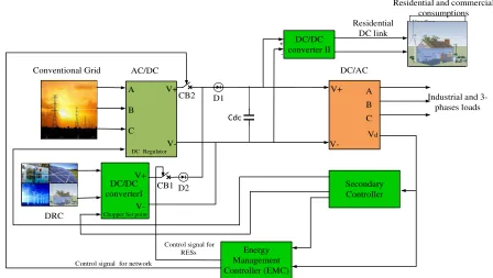
This paper investigates an HMG to provide appropriate operating conditions for the system via local and secondary control loops. The applied topology is shown in Fig. 1. The output of the distributed energy resources is collected in a Distributed Resource Center (DRC), and then the output of DRC is available for consumers in DC form. As shown in Fig. 1, consumers in the power grid are divided into two main categories: urban consumers (residential and commercial) and industrial consumers. According to recent studies, the majority of residential and commercial operate in DC form. In order to reduce unnecessary power conversions, urban electric grid and industrial centers which often use three-phase power are developed in DC and AC forms, respectively. Each of the power converters has its own proper local control loop. In addition, the secondary control loop is used to protect and maintain variables of the system under different operations. In order to interchange economic power, the emergency/central control loop is employed. It is responsible to maintain grid/microgrid stability and secure economic power transmission.
A
B
C
V+
V-D2 Secondary
Controller Conventional Grid
DRC
AC/DC
DC Regulator
Chopper Set point
DC/DC converterІ
V+
V-DC/AC
Industrial and 3- phases loads
Vd
Energy Management Controller (EMC) CB1
CB2
Control signal for network
DC/DC converter ІІ
+
-Residential and commercial consumptions Residential
DC link
A B
C
V+
Control signal for RESs
Cdc
D1
Fig. 1. Hybrid AC-DC microgrid topology
Since AC consumers are fed by a DC link in this type of topologies, any change in energy consumption influences the DC link voltage directly, and hence the voltage of the consumer side will change uncontrollably.
International Journal of Industrial Electronics, Control and Optimization
demand fluctuations
modeling
resources (DERs) are collected in the
link directly and the output of
The HMG shown in Fig. 2 consists of four controllers: AC/DC converter controller,
secondary controller, and
As mentioned, the three
Isolated Gate Bipolar Transistors (IGBT
converter. In several studies, just diodes have been used AC/DC converter
output voltage been used to control
regulator is one of the main controllers for ensuring a load
International Journal of Industrial Electronics, Control and Optimization
demand fluctuations
II.
S
YSTEM CONFIGURATIONGrid configuration is of paramount importance in system modeling. In this paper, the
resources (DERs) are collected in the DRC are DC.
link directly and the output of
The HMG shown in Fig. 2 consists of four controllers: AC/DC converter controller,
secondary controller, and
A. AC/DC converter controller
As mentioned, the three
Isolated Gate Bipolar Transistors (IGBT
converter. In several studies, just diodes have been used AC/DC converter
output voltage [18,24] been used to control
regulator is one of the main controllers for ensuring a load
Vdc
International Journal of Industrial Electronics, Control and Optimization
demand fluctuations on the voltage of the AC demand side.
YSTEM CONFIGURATION
Grid configuration is of paramount importance in system . In this paper, the outputs of the
resources (DERs) are collected in
DRC are DC. An AC/DC converter is connected to the DC link directly and the output of the
The HMG shown in Fig. 2 consists of four controllers: AC/DC converter controller, B)
secondary controller, and D) an inverter controller.
AC/DC converter controller
As mentioned, the three-phase conventional grid is rectified by Isolated Gate Bipolar Transistors (IGBT
converter. In several studies, just diodes have been used AC/DC converters, and consequently
[18,24]. In this paper, tw
been used to control the DC link voltage. The DC voltage regulator is one of the main controllers for ensuring a load
dc R PI2 Vdc-ref I dq-ref-VS
+-International Journal of Industrial Electronics, Control and Optimization
n the voltage of the AC demand side.
YSTEM CONFIGURATION AND MODELING
Grid configuration is of paramount importance in system outputs of the distributed energy resources (DERs) are collected in a DRC. The output voltages of AC/DC converter is connected to the DC the DRC is connected to the DC
Fig.
The HMG shown in Fig. 2 consists of four controllers: ) a boost chopper controller,
inverter controller.
AC/DC converter controller
phase conventional grid is rectified by Isolated Gate Bipolar Transistors (IGBTs) via an AC/DC converter. In several studies, just diodes have been used
equently, there is no control on the . In this paper, two main controllers have
DC link voltage. The DC voltage regulator is one of the main controllers for ensuring a load
R1 L1 Current Controller PWM ref-1 Mdq-1 V d q -1 I d q -1 abc dq abc dq (a)
International Journal of Industrial Electronics, Control and Optimization
n the voltage of the AC demand side.
AND MODELING
Grid configuration is of paramount importance in system distributed energy DRC. The output voltages of AC/DC converter is connected to the DC DRC is connected to the DC
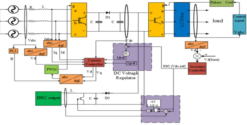
Fig. 2. Performed case study with their controllers
The HMG shown in Fig. 2 consists of four controllers: A) boost chopper controller, C inverter controller.
phase conventional grid is rectified by ) via an AC/DC converter. In several studies, just diodes have been used as
there is no control on the o main controllers have DC link voltage. The DC voltage regulator is one of the main controllers for ensuring a load
Cdc PWM Vdc 6 Rectifier θ
International Journal of Industrial Electronics, Control and Optimization
Grid configuration is of paramount importance in system distributed energy DRC. The output voltages of AC/DC converter is connected to the DC DRC is connected to the DC
link by a boost chopper. Then, three connected at the end of DC link by a three
Each converter locally controls its output based on the given set point. The proposed secondary controller
determine the set point of converter
controllers
. Performed case study with their controllers
) an C) a
phase conventional grid is rectified by
there is no control on the o main controllers have
following
grid and AC/DC converter with its controller. As sh
a three-phase power source is converted to DC voltage by using IGBTs, and
switching according to its set point. two units: a)
the DC voltage regulator block, to its set point,
controller.
Vdc PI
VS
Vdc
Vdc-ref (t)
-+
International Journal of Industrial Electronics, Control and Optimization
link by a boost chopper. Then, three connected at the end of DC link by a three
Each converter locally controls its output based on the given set point. The proposed secondary controller
determine the set point of
converter, and boost chopper. The performed case study and their controllers are shown in Fig. 2.
. Performed case study with their controllers
following the DC link voltage. Fig. 3 depicts the conventional grid and AC/DC converter with its controller. As sh
phase power source is converted to DC voltage by using IGBTs, and the DC regulator produces
switching according to its set point. two units: a) a DC voltage regulator, and b)
DC voltage regulator block,
to its set point, and then the error signal passes through the PI controller. R1 L1 PI2 Current Controller Idq-ref-1 V dq -1 I d q -1 abcdq abc (b)
dc-ref (t-∆t)
Vdc (base)
+ +
International Journal of Industrial Electronics, Control and Optimization .
© 2019 IECO
link by a boost chopper. Then, three connected at the end of DC link by a three
Each converter locally controls its output based on the given set point. The proposed secondary controller
determine the set point of the two main convert
and boost chopper. The performed case study and their are shown in Fig. 2.
DC link voltage. Fig. 3 depicts the conventional grid and AC/DC converter with its controller. As sh
phase power source is converted to DC voltage by using DC regulator produces
switching according to its set point. The DC voltage regulator, and b)
DC voltage regulator block, the DC link voltage is compared then the error signal passes through the PI
Current Controller PWM Mdq-1 6 Rectifier dq θ M Secondary Controller
© 2019 IECO
link by a boost chopper. Then, three-phase consumers are connected at the end of DC link by a three-phase DC/AC inverter. Each converter locally controls its output based on the given set point. The proposed secondary controller was
two main convert
and boost chopper. The performed case study and their
DC link voltage. Fig. 3 depicts the conventional grid and AC/DC converter with its controller. As shown in Fig. 2,
phase power source is converted to DC voltage by using DC regulator produces a pattern of IGBT
The DC regulator includes DC voltage regulator, and b) a current regu
DC link voltage is compared then the error signal passes through the PI
Cdc
Vdc
Rectifier
Vd-2(t) +
-Vd-ref Secondary Controller
© 2019 IECO
….
223phase consumers are phase DC/AC inverter. Each converter locally controls its output based on the given was designed to two main converters, AC/DC and boost chopper. The performed case study and their
DC link voltage. Fig. 3 depicts the conventional own in Fig. 2, phase power source is converted to DC voltage by using
pattern of IGBT DC regulator includes
+ - PI1-d ++
L1
×
L1
+ +
×
+
-/
/
ω
Iq-1
Id-1
Iq-ref-1
Id-ref-1
Vsd
Vsq
1/2Vdc
Md-1
Mq-1
-+ -1
PI1-q
-1
(c)
Fig. 3. Block diagram of (a) the conventional rectifier with a constant value DC-link voltage regulator circuit, and (b) the modified rectifier with a dynamic DC-link voltage regulator circuit, and (c) the current controller scheme.
The output signal of the DC voltage regulator is a current reference for the current regulator. The structure of the current controller in rectifier is the same as the current controller in the inverter. The direction of the current is assumed positive when the current is sent from DC to AC side. However, the direction of the current in rectifiers is the opposite of that in the inverters [26,29]. Also, the output of the current regulator produces a reference
signal , and it would be converted to three-phase. The IGBT
switching is done by Pulse Width Modulation (PWM).
B. Boost chopper controller
Chopper is a DC/DC converter with variable output voltage capability which can be applied in buck, boost and buck-boost configurations. The chopper used in this paper is a boost one which converts 200V output voltage level of DRC into 850 V DC link. The boost chopper circuit is displayed in Fig. 4.
Fig. 4. Block diagram of (a) the conventional boost chopper with constant output value (constant duty ratio) circuit, and (b) the modified boost chopper with variable output (variable duty ratio).
As shown in Fig 4.(a), the duty ratio of IGBT will be constant due to specified input and output voltage. But, in Fig 4. (b) the boost chopper output voltage will be variable with AC side load demand. In normal conditions, the DC link voltage value is 850 V. The increment (reduction) of consumption in the AC side may lead to a reduction (increment) in the load voltage. Hence, AC side voltage is compared with its reference, and the output of the secondary controller (is a DC link reference) is sent to the boost chopper for determining the IGBT duty ratio. The output voltage of boost chopper is calculated by:
input output
V
V =
1-K (1)
The input voltage and DC link voltage are 200V and 850V, respectively. In addition, K as the duty ratio would be 76.5%. Having the time-varying DC link voltage isthe basic principle in our research. Hence, for a variable output voltage, variable K is required. Using Eq. (1), the following equation is achieved.
setpoint input variable
setpoint
V -V
K =
V (2)
where Kvariableis the IGBT duty ratio and Vsetpoint is equal to
output
V . The output voltage of the boost chopper is determined
by the secondary controller. Vsetpoint is the output signal of the
International Journal of Industrial Electronics, Control and Optimization .
© 2019 IECO
….
225C. Secondary controller
The power balancing and DC link voltage dynamics are described below. The network and output of DRC are the electric power sources in this work.
2
2 dc dc
IN V SI C dV
P P
dt = − (3)
where PIN is the injection power from sources to system and
V SI
P is the sending power to three-phase consumers by the inverter. The sending power by the inverter is equal to the power demand and power losses in the AC side as given in (4).
VSI LINE LOAD
P =P +P (4)
In distributed networks, power losses can be neglected when
1 LINE
LINE X
R ≥ .
V SI LOAD
P ≈P (5)
As mentioned, the injection power to the system is composed of the electrical network by the rectifier and DRC output by the boost chopper.
IN rectifier DRC
P =P +P (6)
In dq frame, the power injection from the rectifier can be shown in the following form.
3 ( )
2
rectifier d d q q
P = V I +V I (7)
3 (2 )
rectifier d q q d
Q = −V I +V I (8)
Assuming Vq =0 for obtaining appropriate control strategies, we
can consider Vq =0; therefore, (7) and (8) can be expressed by
(9) and (10). As a result, the active power is controlled by Id and
the reactive power withIq. On the other hand, Id and Iqare
controlled by Idq_ref1 as shown in Figures 2 and 3(b). Hence,
with DC link voltage control the Idq_ref1 signal is created and Id
and Iqwill then be controlled. In the other word, the active and
reactive power of rectifiers can be controlled by control of the DC link voltage.
3 ( ) 2 GRID d d
P = V I (9)
3 ( )
2
GRID d q
Q = −V I (10)
The injected power from the DRC to the system can be expressed by (11). The output active power from boost chopper is controlled by the DC link voltage.
( )
DRC dc out chopper
P = V I − (11)
According to the above description, by controlling DC link voltage, the active power from the rectifier and boost chopper is controlled.
In HMGs with constant DC regulator, the DC link voltage does not change with changes in load demand. However, the AC side consumer voltage is changed because the DC link could not supply the power demand. In this study, the DC link has a dynamical DC voltage regulator, and a simple and robust algorithm is developed to damp the changes in the consumer
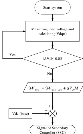
voltage due to the changes in load demand. The flowchart of the proposed algorithm is shown in Fig. 5.
Fig. 5 displays the secondary controller algorithm. After running, the voltage of the system is measured, and Vd is obtained via park transformer, and ∆Vd shown in the flowchart is calculated as follows.
1
d d
V V
∆ = − (12)
If ∆Vd is less than 0.05 pu, DC link voltage will remain constant.
But, if ∆Vd is higher than 0.05 pu, the secondary controller will change the set point value. For example, the load voltage is reduced when the power consumption increases.
In this case, to compensate for the load voltage variation, DC link voltage must increase and vice versa. The DC link voltage percentage is calculated as follows.
( ) ( )
%Vdc t =%Vdc t− ∆t + ∆V Md (13)
where %Vdc(t− ∆t) is the percentage of load voltage at time step
(t − ∆t), and ∆V Md is the perturbation parameter. M is a
constant coefficient to reduce load voltage deviation. As already mentioned, load voltage is inversely proportional to power consumption, and this condition is illustrated in Eq. (12). If the load voltage is increased, the Vd value will exceed 1 pu, and the result of Eq. (12) will be negative. This negative signal will magnify with the impact factor (M) and will be added to the DC
link voltage at time step of
(
t
−
∆
t
)
. The DC link voltage will bedecreased because the obtained signal is negative. The Signal of Secondary Controller (SSC) obtained by Eq. (13) is multiplied by base DC link voltage. The SSC determines the set point of controllers for the DC regulator and boost chopper. As a result, the DC link voltage is dynamically compensated for when the load demand is changed.
Yes
|∆Vd|≤ 0.05 Start system
Measuring load voltage and calculating Vdq(t)
Vdc (base)
No
Signal of Secondary Controller (SSC)
( ) ( )
%Vdc t =%Vdc t−∆t + ∆V Md
+ +
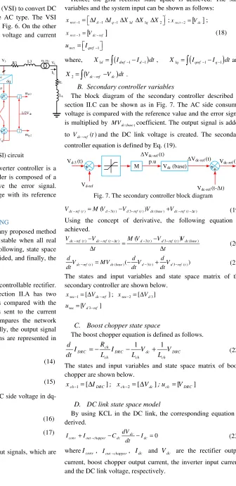
D.DC/AC converter controller
Here, we used a Voltage Source Converter (VSI) to convert DC to AC voltage because most consumers are AC type. The VSI configuration and its controller are shown in Fig. 6. On the other hand, an LC filter is used to eliminate the voltage and current ripples.
V2
V3 V
L
IL
+ - PI3-d +
-L2
×
L2
+
×
PI3-q
+
-/
/
ω
Iq-2
Id-2
Iq-ref-2
Id-ref-2
Vd3
Vq3
1/2Vdc
md-2
mq-2
abc dq
Rf Lf R3 L3
abc dq +
_ Vdc
Cdc
LL
Cf
n1:n2
+
++
RL
Fig. 6. Voltage Source Inverter (VSI) circuit
As shown in Fig. 6, the output of the inverter controller is a PWM reference signal. The inverter controller is composed of a comparator and a PI controller to remove the error signal. Comparator block compares the load voltage with its reference and produces an error signal.
III.
S
TATE SPACE MODELINGSystem stability analysis is necessary for any proposed method of control in MGs. Generally, a system is stable when all real values of eigenvalues are negative. In the following, state space equations of the HMG components are provided, and finally, the state space equation is achieved.
A. Rectifier state space
Three-phase gird voltage is rectified by a controllable rectifier. The controllable rectifier introduced in Section II.A has two control loops. First, the DC link voltage is compared with the reference value and the DC error signal is sent to the current controller. Later, the current controller compares the network current with their reference values, and finally, the output signal is sent to the PWM. The following equations are represented in dq-frame:
1
1 0 1 1 2
1 1 1
1 1
( d ) q d sd d
d R
I I I V V
dt − =ω − −L − +L −L − (14)
1
1 0 1 1 2
1 1 1
1 1
( q ) d q sq q
d R
I I I V V
dt − = −ω − −L − +L −L − (15)
The relation between DC link voltage and AC side voltage in dq-frame can be expressed as below.
2 dc2 1
d d
V
V − = m −
(16)
2 dc2 1
q q
V
V − m −
=
(17)
wheremd−1and mq−1 are the controller output signals, which are
sent to the PWM unit.
Hence, the grid rectifier state apace is achieved. The state variables and the system input can be shown as follows:
'
1 1 1 1 1 2
rect d q d q
x − = ∆ I − ∆I − ∆X ∆X ∆X ;xrect−2=
[
Vdc]
;[
]
3
rect dc ref
x − =V − (18)
1
rect qref
u =I −
where, X1d =
∫
(
Idref−1−Id−1)
dt, X1q=∫
(
Iqref−1−Iq−1)
dtand(
)
2 dc ref dc
X =
∫
V − −V dt .B. Secondary controller variables
The block diagram of the secondary controller described in section II.C can be shown as in Fig. 7. The AC side consumer voltage is compared with the reference value and the error signal is multiplied by MVdc base( )coefficient. The output signal is added
to Vdc ref− ( )t and the DC link voltage is created. The secondary
controller equation is defined by Eq. (19).
+ - ++
Vd-3 (t)
Vd-ref
M
Vdc-ref (t-∆t)
∆Vdc-ref (t)
p.u Vdc-ref (t)
Vdc (base)
∆Vdc-ref (t)
Fig. 7. The secondary controller block diagram
( ) ( 3( ) 3 ( )) ( ) ( )
dc ref t d t d ref t dc base dc ref t t
V − =M V − −V − V +V − −∆ (19)
Using the concept of derivative, the following equation is achieved.
( ) ( ) ( 3( ) 3 ( )) ( )
dc ref t dc ref t t d t d ref t dc base
V V M V V V
t t
− − − − ∆ − − −
=
∆ ∆ (20)
( ) ( )( 3( ) 3 ( ))
dc ref t dc base d t d ref t
d d d
V MV V V
dt − = −dt − +dt − (21)
The states and input variables and state space matrix of the secondary controller are shown below.
sec 1 [ dc ref]
x − = ∆V − ; xsec 2− = ∆[ Vd3]
sec [ d3ref] u =V −
C. Boost chopper state space
The boost chopper equation is defined as follows.
1 1
ch
DRC DRC dc DRC
ch ch ch
R d
I I V V
dt = −L −L +L (22)
The states and input variables and state space matrix of boost chopper are shown below.
1 [ ]
ch DRC
x − = ∆I ; xch−2= ∆[ Vdc]; uch =[VDRC]
D. DC link state space model
By using KCL in the DC link, the corresponding equation is derived.
0 dc
conv out chapper dc dc dV
I I C I
dt −
+ − − = (23)
whereIconv, Iout chapper− , Idc and Vdc are the rectifier output
International Journal of Industrial Electronics, Control and Optimization .
© 2019 IECO
….
227In an ideal converter, the input and output power is equal. Hence, the following equations are defined.
in out
P =P (24)
3 ( )
2
dc dc d d q q
V I = V I +V I (25)
As the result, the rectifier, inverter and chopper current equations are expressed as follows.
1 1 1 1
3 ( )
4
conv d d q q
I = I −m +I −m (26)
2 2 2 2
3 ( )
4
dc d d q q
I = I −m +I − m (27)
DRC out chopper DRC
dc V I I V − = (28)
The above equations are nonlinear, and the linearized dynamic model of the boost chopper is expressed as follows.
2
DRC nom DRC nom
out chopper DRC DRC
dc nom dc nom
DRC nom DRC nom dc dc
V I
I I V
V V V I V V − − − − − − − ∆ = ∆ + ∆ − ∆ (29)
E. VSI state space model
DC voltage is converted to three-phase consumers by a VSI. According to Fig. 6 for a VSI, the following equations are expressed.
2 0 2 2 2 3
1 1
( ) f
d q d d d
f f f
d R
I I I V V
dt ∆ − =ω − −L − +L − −L − (30)
2 0 2 2 2 3
1 1
( ) f
q d q q q
f f f
d R
I I I V V
dt ∆ − = −ω − −L − +L − −L − (31)
The load current and voltage equations are as follows:
2
2 1 1
0 3
2 2 2 2 2
( ) 1 1
( ) ( )
d L
q L d L d d L
d I R N N
I I V V
dt ω L L N L N
−
− − − −
∆
= − + − (32)
2
2 1 1
0 3
2 2 2 2 2
( ) 1 1
( ) ( )
q L
d L q L q q L
d I R N N
I I V V
dt ω L L N L N
−
− − − −
∆
=− − + − (33)
2
3 0 3 2
1
1 1
( d ) q d ( ) d L
f f
d N
V V I I
dt ∆ − =ω − +C − −C N − (34)
2
3 0 3 2
1
1 1
( q ) d q ( )q L
f f
N d
V V I I
dt ∆ − = −ω − +C − −C N − (35)
Using a KVL in the load side for the load voltage, the following equations are obtained.
2 1 1 2 2 2 0 3 2 2 ( ( ) ( )
( ) L
d L
q L d L d
N N
R R
d I N N
I I V
dt ω QL QL
− − − − + ∆ = − + (36) 2 1 1 2 2 2 0 3 2 2 ( ( ) ( )
( ) L
q L
d L q L q
N N
R R
d I N N
I I V
dt ω QL QL
− − − − + ∆ = − − + (46)
where, 1 2
2 2
1 LL(N )
Q
L N
= + . The state and inputs variables are
shown below.
'
2 2 3 3 3 3
inv d q d q d L q L d q
x = ∆ I − ∆I − ∆V − ∆V − ∆I − ∆I − ∆X ∆X
2 2
inv d ref q ref
u =I − − I − −
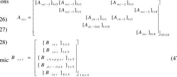
D.Overall system state space model
For small signal stability analysis of the system, the overall state space matrices are required. According to the system configuration and their relative state space equations, the overall state matrix can be achieved as
1 5 5 3 5 1 2 5 1
1 1 1 2 1 8
1 1 1 2 1 1
1 1 6
8 8 1 6 1 6
[ ] [ ] [ ]
[ ] [ ]
[ ] [ ]
[ ]
[ ]
re c re c re c
se c se c
sy s ch c h
d c lin k
in v
A A A
A A
A A A
A A − × − × − × − × − × − × − × − × × × = 5 5 1 5 1 5 1 5
8 5 1 6 5
[ ]
[ ]
[ ]
[ ]
[ ]
r e c
s e c
s y s c h o p p e r
d c l i n k
i n v
B B B B B B × × × − × × × = (47)
IV.
F
REQUENCY RESPONSE AND STABILITY ANALYSISThe HMG eigenvalues are shown in Fig. 8. As shown in this figure, all real parts of eigenvalues are located in the left-hand side of the imaginary axis in the presence of a secondary controller.
Root locus and Bode plots are applied for stability analysis using the following transfer function.
1
d s
dc dc ref I G V V − − = − (48)
where Vdc−Vdc ref− is the DC error signal.
Fig. 8. The HMGs eigenvalues
The root locus and Bode plots are shown in Figs. 9(a) and 9(b), respectively.
-80 -70 -60 -50 -40 -30 -20 -10 0
(a)
(b)
Fig. 9. Small signal rectifier error signal: (a) root locus, (b) Bode plot
As shown in the Bode plot, the closed loop of a specific transfer function without a secondary controller is unstable when the load of the system increases to 1.3 pu, but the system within the secondary controller is stable. The gain margin in the stable system is 21.4 (dB) at frequency 21.4 (rad/sec) and the phase margin is 18.1 (deg) at frequency 4.9 (rad/sec). The root locus plot shows that the system is always stable when the DC gain of the transfer function is less than the critical DC gain (shown in
root locus plot and equals to 8.7 10× 4). According to the
maximum load disturbance and the DC link voltage deviation, the DC gain of the transfer function is much less than the critical DC gain. As a result, the system is stable.
V.
S
IMULATION RESULTSThe proposed algorithm is implemented on the given case study system described in the previous section. The DC link voltage in normal conditions (base load) is 850 V. AC/DC converter rectifies the conventional grid from 400 V AC to 850 V DC, and the boost chopper increases the output of DRC from 200 V DC to 850 V DC. Three-phase consumers are connected to the system by a three-phase inverter. The inverter changes the DC link voltage to 380 V AC at 60 Hz while the base local load demand is
60 kW, and two scenarios regarding increasing and decreasing the load are studied. Table 1 presents the system parameters that are given in APPENDIX A.
A. Without secondary controller
In this case, the load voltage is varied by the load changes if the hybrid system lacks a secondary controller. The maximum acceptable range for load voltage variations is ± 5% pu. For small load fluctuations, the system can maintain the AC side load voltage within this range. But, Fig. 10 clearly shows that the load voltage decreases to 0.81 pu between 0.8-1.3s duration when the consumption power increases to up to 30%. As shown, this reduction for the system voltage is not acceptable from an operation system point of view. Also, Fig. 10(b) shows the DC link voltage under load variations. As mentioned in the previous section, the DC link voltage is fixed at 850 V without any changes. Likewise, when the power consumption decreases to 70% of the base load, the load voltage increases to 1.25 pu without any changes in the DC link voltage. Fig. 11 clearly confirms this fact.
(a)
(b)
Fig. 10. Load voltage under disturbance without a secondary controller. a) AC side voltage, b) DC link voltage
Root Locus
Real Axis (seconds-1)
Im
a
g
in
a
ry
A
x
is
(
s
e
c
o
n
d
s
-1)
-150 -100 -50 0 50
-800 -600 -400 -200 0 200 400 600 8000.17
0.24
0.36
0.6
0.025 0.05 0.08 0.12 0.17 0.24 0.36 0.6
200 400 600 800
200
400
600
800 0.025 0.05 0.08 0.12
System: untitled1 Gain: 8.73e+04 Pole: -0.0177 + 728i Damping: 2.44e-05 Overshoot (%): 100 Frequency (rad/s): 728
10-1 100 101 102 103 104
-270 -180 -90 0
P
h
a
s
e
(
d
e
g
)
Frequency responce of transfer function TF=I
d1/(Vdc-Vdcref)
Frequency (rad/s) -150
-100 -50 0 50
System: With secondary controller Gain Margin (dB): 21.4 At frequency (rad/s): 20.4 Closed loop stable? Yes
System: Without secondary controller Gain Margin (dB): 98.8 At frequency (rad/s): 727 Closed loop stable? No
M
a
g
n
it
u
d
e
(
d
B
)
With secondary controller Without secondary controller
0.7 0.8 0.9 1 1.1 1.2 1.3 1.4
Time(sec) (a) -1
-0.5 0 0.5 1
0.75 0.8 0.85
Time(sec) (b) -1
-0.5 0 0.5 1
1.25 1.3 1.35
Time(sec) (c) -1
International Journal of Industrial Electronics, Control and Optimization .
© 2019 IECO
….
229Fig. 11. Load voltage under decreased load demand
B. With secondary controller
In this section, load variations in the presence of a secondary controller are investigated. The results show that the secondary controller influences the power system stability. Fig. 12(a) plots load voltage when the power consumption is decreased down to 70% (42 kW) in 1.3-1.70s time duration.
(a)
(b)
Fig. 12. Load voltage under disturbance with a secondary controller. a) AC consumer voltage, b) DC link voltage
Without a secondary controller, the load voltage increases up to 1.25 pu, but the load voltage returns to the initial condition after 20 ms without any deviations when the secondary controller is presented. Returning to the initial situation when there are not any disturbances in the system is one of the main challenges for every controller. Indeed, the controller should be able to return to the initial condition. Fig. 12(a) shows that the load voltage quickly returns to the previous situation after the end of disturbance. The main reason of this change is the variations occurred at the DC link voltage. As shown in Fig. 12(b), the DC link voltage will be changed due to the fluctuations at the set point of two main controllers (grid rectifier and boost chopper) whereas the set point value is determined by the SSC.
The initial value of the DC link voltage is 850 V and it is constant before any disturbances. At 1.3s, the power consumption decreases up to 70% of the initial value and SSC changes the output of the AC/DC converter and boost chopper quickly. In addition, the DC link voltage is decreased to 690 V as shown in Fig. 14 at 1.55 s (25 ms after eliminating the disturbance). Therefore, the three-phase load voltage comes back to the initial value quickly by decreasing the DC link voltage. The variations of the load current are shown in Fig. 13.
Fig. 13. Load current under the decrease in load demand
(a)
(b)
Fig. 14. Load voltage and current under 30% increase in load demand, respectively.
As shown in Fig. 14, the consumer voltage comes back to the
initial value in less than 20 ms after disturbance (an increase by 30% power demand). In fact, the DC link set point is changed by the SSC. On the other hand, after the elimination of disturbance,the DC link voltage comes back to the initial values. Hence, the consumer voltage returns to the initial values. Fig. 15 plots the variations of the DC link voltage over time. After disturbance, the
DC link voltage is increased from 850 V to 1020 V to supply the load demand without any decreases in load voltage.
Fig. 15. The DC link voltage when load demand is increased
VI.
C
ONCLUSIONIn order to enhance the use of renewable energy resources in electrical systems, an effective control plan must be provided in all operating conditions. In fact, hybrid AC-DC MGs can be expressed as a future ideal electrical MG. In this paper, a DC link is used to connect an electric power producer such as a conventional power system and DGs whose outputs are collected in DRC. Conventional power grids can be converted to DC by an AC/DC converter, and the voltage level of DRC can be changed by a boost chopper. They are connected with DC link and connect a phase consumer to the DC link by a three-phase inverter. In current research, a new control algorithm is proposed for damping load variation effects. By setting the set point of controllers, the proposed controller could produce dynamical DC link voltage. Accordingly, the load changing in power system can be controlled widely. The SSC determines the set point of AC/DC converter and boost chopper. The matrices of the system state space are calculated, and the stability analysis is done. All of the system eigenvalues are on the left-hand side of the imaginary axis when a secondary controller is applied. It was shown that the system became unstable without the secondary controller. Also, the system stability was investigated by the root locus diagram. By implementing the proposed controller, it was observed that the load voltage had a small variation in a wide range of load variations. According to the results, the proposed controller is fast, simple, and robust against load disturbances.
A
PPENDIX.A
SYSTEM PARAMETERS Table 1. The system parameters
Rectifier parameters Value Inverter parameters Value
7.3 5
7.5 9
43.1 33
42 30
25.8 2 mΩ
0.175 10 µH
0.12 Ω 350 µF
0.04 H : 1
Chopper parameters Value 60 Hz
0.765 1.1 Ω
2 mH 0.16 H
46 µF Secondary parameter Value
International Journal of Industrial Electronics, Control and Optimization .
© 2019 IECO
….
231R
EFERENCES[1] Bevrani H, Ise T. Microgrid dynamics and control. John
Wiley & Sons; 2017.
[2] Lidula NWA, Rajapakse AD. Microgrids research: A review of experimental microgrids and test systems. Renew Sustain
Energy Rev 2011;15:186–202.
[3] Soshinskaya M, Crijns-Graus WHJ, Guerrero JM, Vasquez JC. Microgrids: Experiences, barriers and success factors. Renew Sustain Energy Rev 2014;40:659–72.
[4] Fathi M, Bevrani H. Statistical cooperative power dispatching in interconnected microgrids. IEEE Trans
Sustain Energy 2013;4:586–93.
[5] Dursun E, Kilic O. Comparative evaluation of different power management strategies of a stand-alone PV/Wind/PEMFC hybrid power system. Int J Electr Power
Energy Syst 2012;34:81–9.
[6] Carmeli MS, Castelli-Dezza F, Mauri M, Marchegiani G, Rosati D. Control strategies and configurations of hybrid distributed generation systems. Renew Energy 2012;41:294– 305.
[7] Eghtedarpour N, Farjah E. Control strategy for distributed integration of photovoltaic and energy storage systems in DC micro-grids. Renew Energy 2012;45:96–110.
[8] Puttgen HB, Macgregor PR, Lambert FC. Distributed generation: Semantic hype or the dawn of a new era? IEEE
Power Energy Mag 2003;99:22–9.
[9] Carr JA, Balda JC, Mantooth HA. A survey of systems to integrate distributed energy resources and energy storage on the utility grid. Energy 2030 Conf. 2008. ENERGY 2008. IEEE, IEEE; 2008, p. 1–7.
[10] Gellings CW. The smart grid: enabling energy efficiency
and demand response. The Fairmont Press, Inc.; 2009.
[11] Planas E, Gil-de-Muro A, Andreu J, Kortabarria I, de Alegría IM. General aspects, hierarchical controls and droop methods in microgrids: A review. Renew Sustain Energy
Rev 2013;17:147–59.
[12] Hossain E, Kabalci E, Bayindir R, Perez R. Microgrid testbeds around the world: State of art. Energy Convers
Manag 2014;86:132–53.
[13] Eghtedarpour N, Farjah E. Power control and management in a hybrid AC/DC microgrid. IEEE Trans Smart Grid
2014;5:1494–505.
[14] Planas E, Andreu J, Gárate JI, de Alegría IM, Ibarra E. AC and DC technology in microgrids: A review. Renew Sustain
Energy Rev 2015;43:726–49.
[15] Unamuno E, Barrena JA. Hybrid ac/dc microgrids—Part I: Review and classification of topologies. Renew Sustain
Energy Rev 2015;52:1251–9.
[16] Hammerstrom DJ. AC versus DC distribution systems did we get it right? Power Eng. Soc. Gen. Meet. 2007. IEEE,
IEEE; 2007, p. 1–5.
[17] Unamuno E, Barrena JA. Hybrid ac/dc microgrids—Part II: Review and classification of control strategies. Renew
Sustain Energy Rev 2015;52:1123–34.
[18] Paska J, Biczel P, Kłos M. Hybrid power systems–An effective way of utilising primary energy sources. Renew
Energy 2009;34:2414–21.
[19] Mohamed A, Elshaer M, Mohammed O. Bi-directional AC-DC/DC-AC converter for power sharing of hybrid AC/DC
systems. Power Energy Soc. Gen. Meet. 2011 IEEE, IEEE;
2011, p. 1–8.
[20] Wang P, Liu X, Jin C, Loh P, Choo F. A hybrid AC/DC micro-grid architecture, operation and control. Power
Energy Soc. Gen. Meet. 2011 IEEE, IEEE; 2011, p. 1–8. [21] Liu X, Wang P, Loh PC. A hybrid AC/DC micro-grid.
IPEC, 2010 Conf. Proc., IEEE; 2010, p. 746–51.
[22] Liu X, Wang P, Loh PC. A hybrid AC/DC microgrid and its
coordination control. IEEE Trans Smart Grid 2011;2:278– 86.
[23] Xia Y, Peng Y, Yang P, Yu M, Wei W. Distributed coordination control for multiple bidirectional power converters in a hybrid AC/DC microgrid. IEEE Trans Power Electron 2017;32:4949–59.
[24] Karabiber A, Keles C, Kaygusuz A, Alagoz BB. An approach for the integration of renewable distributed generation in hybrid DC/AC microgrids. Renew Energy
2013;52:251–9.
[25] Ma Y, Cao W, Yang L, Wang FF, Tolbert LM. Virtual Synchronous Generator Control of Full Converter Wind Turbines With Short-Term Energy Storage. IEEE Trans Ind
Electron 2017;64:8821–31.
[26] Bottrell N, Prodanovic M, Green TC. Dynamic stability of a microgrid with an active load. IEEE Trans Power Electron
2013;28:5107–19.
[27] Radwan AAA, Mohamed YA-RI. Linear active stabilization of converter-dominated DC microgrids. IEEE Trans Smart
Grid 2012;3:203–16.
[28] Yazdani A, Dash PP. A control methodology and characterization of dynamics for a photovoltaic (PV) system interfaced with a distribution network. IEEE Trans Power
Deliv 2009;24:1538–51.
research area c
o
research interest are power control.
Kumamoto University (Japan), Queensland University of Technology (Australia), Kyushu Institute of Technolog
Lille (France), and Technical University of Berlin (Germany). He is the author of
more than 300 journal/conference papers. interests include
system stability,
intelligent/robust control applications in power electric industry.
research areas are control, generation optimization.
research interest are power control.
Kumamoto University (Japan), Queensland University of Technology (Australia), Kyushu Institute of Technolog
Lille (France), and Technical University of Berlin (Germany). He is the author of six
more than 300 journal/conference papers. interests include
system stability,
ntelligent/robust control applications in power electric industry.
Yousefreza Jafarian Jelodar
M.Sc. degree in Power System Engineering from Shahid Bahonar University
Iran in 2011. He is currently
of Power Systems Control in Kurdistan University, Sanandaj, Iran. His main interest are power electronic
eneration maintenance
Amin Karimi
Electrical Engineering from Educational Research Complex of Isfahan, Iran, in 2005 and his M.Sc. degree in Analog Electronic Engineering from Razi University, Kermanshah, Iran in 2009. He is currently Ph.D. Student of Power Systems Control in Kurdistan University, Iran. His main areas of research interest are power electronic,
Hassan Bevrani
Electrical Engineering from Osaka University in 2004. Currently, h
the Program Leader of Micro/Smart Grids Research Center (SMGRC) at the University of Kurdistan.
has cooperated
Kumamoto University (Japan), Queensland University of Technology (Australia), Kyushu Institute of Technolog
Lille (France), and Technical University of Berlin (Germany). He six international books, 15 book chapters, and more than 300 journal/conference papers.
interests include smart grid operation and control, p system stability, microgrid dynamics and control, and
ntelligent/robust control applications in power electric
Yousefreza Jafarian Jelodar
ree in Power System Engineering from Shahid Bahonar University
Iran in 2011. He is currently
Systems Control in Kurdistan University, Sanandaj, Iran. His main interest
lectronics, hybrid m aintenance scheduling and
Amin Karimi received his
Electrical Engineering from Educational Research Complex of Isfahan, Iran, in 2005
M.Sc. degree in Analog Electronic Engineering from Razi University, Kermanshah, Iran in 2009. He is currently
Student of Power Systems Control in niversity, Iran. His main areas of lectronic, virtual inertia, and
Hassan Bevrani received his
ngineering from Osaka University in 2004. Currently, he is a full professor and Program Leader of Micro/Smart Grids Research Center (SMGRC) at the University of Kurdistan. Over the years, he cooperated with Osaka University, Kumamoto University (Japan), Queensland University of Technology (Australia), Kyushu Institute of Technolog
Lille (France), and Technical University of Berlin (Germany). He international books, 15 book chapters, and more than 300 journal/conference papers. His current research
mart grid operation and control, p icrogrid dynamics and control, and ntelligent/robust control applications in power electric
Yousefreza Jafarian Jelodar received his ree in Power System Engineering from Shahid Bahonar University of Kerman, Iran in 2011. He is currently a Ph.D. student Systems Control in Kurdistan University, Sanandaj, Iran. His main interest microgrid, robust cheduling and power system
his B.E. degree in Electrical Engineering from Educational Research Complex of Isfahan, Iran, in 2005
M.Sc. degree in Analog Electronic Engineering from Razi University, Kermanshah, Iran in 2009. He is currently a Student of Power Systems Control in niversity, Iran. His main areas of nertia, and robust
his Ph.D. degree in ngineering from Osaka University e is a full professor and Program Leader of Micro/Smart Grids Research Center (SMGRC) at the Over the years, he with Osaka University, Kumamoto University (Japan), Queensland University of Technology (Australia), Kyushu Institute of Technology, Centrale Lille (France), and Technical University of Berlin (Germany). He international books, 15 book chapters, and His current research mart grid operation and control, power icrogrid dynamics and control, and ntelligent/robust control applications in power electric his ree in Power System Engineering , Ph.D. student Systems Control in Kurdistan University, Sanandaj, Iran. His main interest obust ystem
B.E. degree in Electrical Engineering from Educational Research Complex of Isfahan, Iran, in 2005 M.Sc. degree in Analog Electronic Engineering from Razi University, a Student of Power Systems Control in niversity, Iran. His main areas of obust