Iranian Journal of Electrical & Electronic Engineering, Vol. 14, No. 3, September 2018 259
Analytical Modeling of Magnetic Field Distribution in Inner
Rotor Brushless Magnet Segmented Surface Inset Permanent
Magnet Machines
A. Jabbari*(C.A.)
Abstract: Brushless permanent magnet surface inset machines are interested in industrial applications due to their high efficiency and power density. Magnet segmentation is a common technique in order to mitigate cogging torque and electromagnetic torque components in these machines. An accurate computation of magnetic vector potential is necessary in order to compute cogging torque, electromagnetic torque, back electromotive force and self/mutual inductance. A 2D analytical method for magnetic vector potential calculation in inner rotor brushless segmented surface inset permanent magnet machines is proposed in this paper. The analytical method is based on the resolution of Laplace and Poisson equations as well as Maxwell equation in a quasi- Cartesian polar coordinate by using sub-domain method. One of the main contributions of the paper is to derive an expression for the magnetic vector potential in the segmented PM region by using hyperbolic functions. The developed method is applied on the performance computation of two prototype surface inset magnet segmented motors with open circuit and on load conditions. The results of these models are validated through FEM method.
Keywords: 2D Analytical Modeling, Segmented Permanent Magnet, Surface Inset DC Machine, Sub-Domain Method, Hyperbolic Functions.
1 Introduction1
rushless permanent magnet motors are interested in industrial applications due to their high efficiency and power density [1-3]. Magnet segmentation is an effective and simple technique for cogging torque reduction in high power permanent-magnet brushless machines. An accurate prediction of air-gap magnetic field distribution is necessary in order to calculate machine performance.
Several researches has been carried out to compute the effect of magnet segmentation on machine performance. An analytical approach is used to predict cogging torque harmonics [4]. The key idea was to set the distribution
Iranian Journal of Electrical & Electronic Engineering, 2018. Paper first received 06 November 2017 and accepted 08 February 2018.
* The author is with the Department of Mechanical Engineering, Faculty of Engineering, Arak University, Arak, 38156-8-8849, Iran. E-mail: [email protected].
Corresponding Author: A. Jabbari.
of the air-gap flux density by segmenting the magnet pole into several elementary magnet blocks.
An experimental examination and three-dimensional numerical analysis by the finite element method is applied to investigate the cogging torque force in a magnet segmented permanent magnet linear synchronous motor [5].
An analytical method was proposed to evaluate the effect of both circumferential and axial segmentations on losses’ reduction in various conditions, concerning the skin effect in a magnet segmented synchronous machine [6]. Finite-element calculation confirms the results of the analysis.
Finite-element analysis (FEA) is used to optimize segmented magnet size in permanent magnet synchronous motor using a multiobjective optimization framework [7].
The effect of eddy current loss reduction by magnet segmentation in synchronous motors with concentrated windings was studied in [8] by using 3-D 3-D finite element analysis with Fourier transformation.
A method for the calculation of eddy current losses in
B
Iranian Journal of Electrical & Electronic Engineering, Vol. 14, No. 3, September 2018 260
the permanent magnets, which takes into account the reaction of induced eddy currents was proposed in [9]. The developed quasi–3-D analytical method considers the effects of axial and circumferential segmentation of magnets.
In [10], the 1D airgap magnetic fields of multiple multilayer 2D finite element simulations are combined to a 2D airgap magnetic field using static simulations. The introduced multilayer-2D - 2D coupled model is used to study the effect of segmentation on the eddy-current loss in the permanent magnets of an axial-flux PM machine simulating different segmentation grades. The axial segmentation of the PMs is employed to cut off the eddy-current axial paths in axial flux permanent magnet motor [11]. A nodal method based network-field coupled multislice time-stepping finite element method (TS-FEM) is proposed to analyze the steady-state and dynamic characteristics of the high-speed PM machine. Segmentation of magnets was proposed to reduce magnet eddy current loss, and finally a new structure based on segmentation was proposed to optimize the eddy current loss [12].
A newly developed high torque density interior permanent magnet motor with a flux concentration configuration design for electric racing cars considering magnet segmentation was proposed in [13].
Magnet segmentation is proposed to meet the overheating challenge [14].
A closed-form 3D analytical model developed for the estimation of eddy current losses in a magnet segmented interior permanent magnet synchronous machine [15]. A two-dimensional (2D) analytical subdomain model is proposed based on virtual PM blocks in magnet segmented PMSM [16].
A closed-form 2D analytical model developed for the estimation of eddy current loss in segmented magnet interior permanent magnet machines [17]. The proposed model can be directly used to evaluate the eddy current magnet loss for magnet segmentation in the circumferential direction.
An investigation of magnet segmentation and its susceptibility to demagnetization in an in-wheel motor for an electric vehicle was carried out in [18]. The analyzed motor is a high torque density, low speed, surface-mounted permanent magnet (SMPM) modular motor with fractional slot concentrated winding (FSCW) and an outer rotor.
Verified simulation models both in 2D and 3D are used to compare a radial flux machine (IPM) with a transverse flux machine (TFM) for a traction application [19]. It also shows the practical handling of loss modelling in 2D and 3D respectively, including a stacking factor for the core lamination and magnet segmentation.
An analytical approach for studying rotor losses in permanent magnet surface mounted synchronous machines considering magnet segmentation was proposed in [20].
A switched flux permanent magnet (SFPM) machine with radially segmented permanent magnets (PMs) is presented in [21]. The thickness of each segment is optimized to maximize the torque performance and reduce the total magnet material volume.
A new structure based on segmentation was proposed to optimize the eddy current loss in [22].
Sub-domain model [23-27] is reported to model electrical machines and are useful in first step of performance evaluation and design optimization stage. The sub-domain model is more accurate than the other analytical models [23].
To the author’s knowledge, a few analytical models are presented to calculate magnetic vector potential in surface inset permanent magnet motors [23-27]. No references in the literature addressing the issue of an analytical model for surface inset magnet segmented machines considering magnet segmentation were found. The focus of this paper is to develop an analytical model based on resolution of Laplace and Poisson equations in surface inset permanent magnet machines by using the sub-domain method considering magnet segmentation and slotting effects. It is shown that the developed model can effectively estimate magnetic vector potential, magnetic flux density, cogging torque and electromagnetic torque. This model is applied on the performance calculation of two prototypes, i.e., a 4 segmented 4P-18S PM surface inset brushless DC motor and a 2 segmented 6P-18S surface inset brushless DC motor. It’s shown that the results of analytical model are in close agreement with the results of FEM. The problem definition and assumptions are presented in Section 2. Analytical expressions of magnetic vector potential in each sub-domain are developed in Section 3. Performance calculation and model validation is described in Section 4.
2 Problem Definition
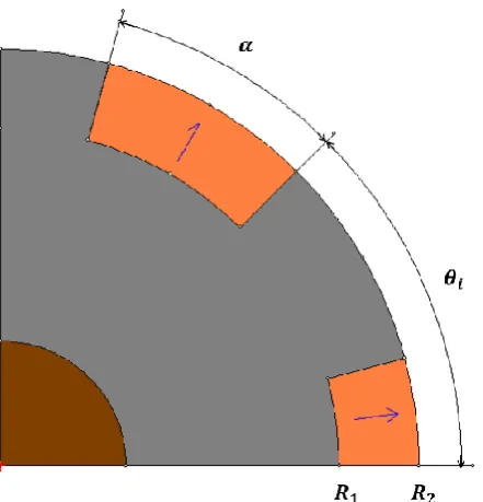
The geometrical representation of the investigated permanent magnet motor with magnet segmented outer rotor layout is shown in Fig. 1. The machine model is divided into three sub-domains including the armature slots region (domain l) which has G1 slots, the air-gap
region (domain I) and the permanent magnet region (domain i) which has G2 magnets. The machine
parameters including the rotor slot inner radius, R1, the
rotor outer radius, R2 , the stator surface radius, R3 , the
stator yoke radius, R4.
The angular position of the j-th armature slot and k-th stator permanent magnet are defined as (1) and (2), respectively.
1 1
2
with 1 2
l
l
l G
G
(1)
2 2
2
with 1 2
i
i
i G
G
(2)
Iranian Journal of Electrical & Electronic Engineering, Vol. 14, No. 3, September 2018 261
Fig. 1 The schematic representation of an inner rotor segmented surface inset PM machine.
3 Magnetic Vector Potential Calculation
General solution of Laplace or Poisson equation in each sub-domain is developed in this section. The Laplace equation can be described in polar form as
2 2
1 2
2 2 2
1 2
1 1
0 for R r R
A A A
r r
r r
(3)
Replacing r by R1e-t, one obtains
1 2 2 2 2 2 1 2 ln 0 0 for R t A A R t (4)
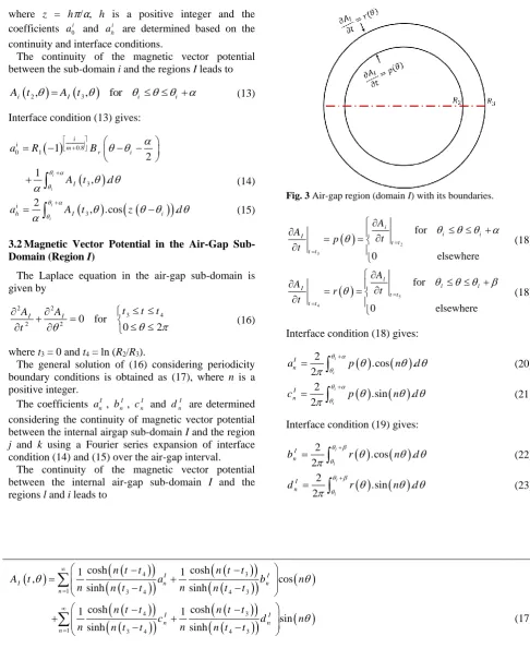
3.1 Magnetic Vector Potential in the Rotor Permanent Magnet Sub-Domain (Region i)
The Poisson equation in the stator permanent magnet sub-domain is given by
2 2 0 2 2 1 2 1 for t
i i ri
k
i i
e
A A M
M R t
t t t
(5)
Fig. 2 Two segmented permanent magnet region (domain i) with its boundaries.
where t1 = 0 and t2 = ln (R1/R2).
The radial and tangential components of radial magnetization for segmented surface inset permanent magnet design can be expressed as
0.81 0
1 with 1, 2, ,
i r m ri
B
M i G
(6)
0 i
M (7)
where m is the number of magnet segmentations. Neumann boundary conditions at the bottom and both sides of the permanent magnet slot are obtained as
0.81 1 i i t i m r A
q t R e B
(8)
0.81 1 i i t i m r A
q t R e B
(9) 1 0 i t t A t (10)
The general solution of (5) is given by
0.8 0 1 1 11 2 1
, ( ) 1
2
cosh 1
. .cos
cosh
i
i t m
i r i
i i t zt
h h i
h
A t a R e t B
z t t
a X R e e z
z
z t t
(11)Iranian Journal of Electrical & Electronic Engineering, Vol. 14, No. 3, September 2018 262
0.8 2 2 4 1if 1, 3, 5, 1
0 if 2, 4, 6,
i i m r h B h
X z z
h (12)
where z = hπ/α, h is a positive integer and the coefficients 0
i
a and i h
a are determined based on the continuity and interface conditions.
The continuity of the magnetic vector potential between the sub-domain i and the regions I leads to
2,
3,
fori I i i
A t A t (13)
Interface condition (13) gives:
0.8 0 1 3 1 2 1 , . i i i i m r i Ia R B
A t d
(14)
3
2
, .cos .
i i i
h I i
a A t z d
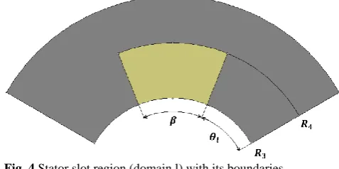
(15)3.2 Magnetic Vector Potential in the Air-Gap Sub-Domain (Region I)
The Laplace equation in the air-gap sub-domain is given by
2 2
3 4
2 2 0 for
0 2
I I t t t
A A
t
(16)
where t3 = 0 and t4 = ln (R2/R3).
The general solution of (16) considering periodicity boundary conditions is obtained as (17), where n is a positive integer.
The coefficients I n
a , I
n
b , I
n
c and I n
d are determined considering the continuity of magnetic vector potential between the internal airgap sub-domain I and the region
j and k using a Fourier series expansion of interface condition (14) and (15) over the air-gap interval. The continuity of the magnetic vector potential between the internal air-gap sub-domain I and the regions l and i leads to
Fig. 3 Air-gap region (domain I) with its boundaries.
23 for 0 elsewhere i i i I t t t t A A t p t (18)
54 for 0 elsewhere l l l I t t t t A A t r t (18)
Interface condition (18) gives:
2 .cos . 2 i i I na p n d
(20)
2 .sin . 2 i i I nc p n d
(21)Interface condition (19) gives:
2 .cos . 2 l l I nb r n d
(22)
2 .sin . 2 l l I nd r n d
(23)
4 31 3 4 4 3
4 3
1 3 4 4 3
cosh cosh 1 1 , cos sinh sinh cosh cosh 1 1 sin sinh sinh I I
I n n
n
I I
n n
n
n t t n t t
A t a b n
n n t t n n t t
n t t n t t
c d n
n n t t n n t t
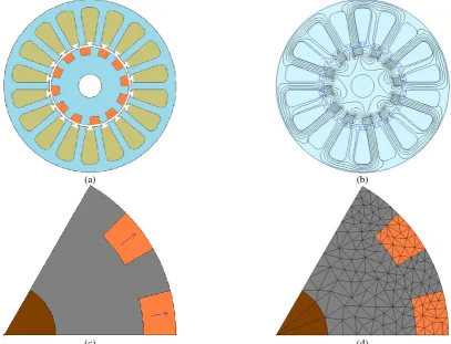
(17)Iranian Journal of Electrical & Electronic Engineering, Vol. 14, No. 3, September 2018 263 3.3 Magnetic Vector Potential in the Stator Slot
Sub-Domain (Region l)
The Poisson equation in the armature slot sub-domain is given by
2 2
5 6
0
2 2 for
l l
l l
t t t
A A
J
t
(24)
where t5 = 0 and t6 = ln (R3/R4).
Neumann boundary conditions at the bottom and at each side of the slot are obtained as
0 and 0
l l l l A A
(25)
6
0
l t tA
t
(26)The general solution of (24) using the separation of variables method is given by (27), where h is a positive integer and the coefficients 0
l
a and l h
a are determined based on the continuity and interface conditions. The continuity of the magnetic vector potential between the sub-domain j and the region I leads to
5,
4,
forl I l l
A t A t (28) Interface condition (28) gives:
6 2 6
0 0 4 1 1 2 2 1 , . l l
t t t
I
i
I
a J e t e
A t d
(29)
4
2
, .cos .
l l I
h I l
h
a A t d
(30)Fig. 4 Stator slot region (domain l) with its boundaries.
4 Performance Calculation and Model Evaluation
In this section, the proposed analytical model is used to study performance characteristics of two prototype motors, i.e., 4P-18S and 6P-18S, in magneto-static and transient modes. The results of analytical method are then verified by the results of finite element method. The motors parameters are given in Table 1. The schematic representation model of two investigated surface inset PM motors and their corresponding magnetic flux distribution obtained by FEA are shown in Fig. 5 and Fig. 6, respectively. The electromagnetic torque is obtained using the Maxwell stress tensor and expressed as
2 0 0 , . , . se r e e
L
T
BI t BI t d (31)where BIr is radial flux density in I region, BI𝜃 is
tangential flux density in I region, LSis the axial length
of the motor and te is calculated by
2 2 3 ln / 2 e e e R t RR R R
(32)
6 6 6 2 0 0 1 5 6 cosh 1 1 , .cos 2 2 cosht t t
l j
l i h l
h
h
t t
h
A t a J e t e a
h t t
(27)Table 1 Parameters of the investigated brushless motors.
Symbol Quantity 4P-18S Motor S=4 6P-18S Motor S=2
R1 Inner radius of the rotor PM 30.2mm 30.2mm
R2 Outer radius of the rotor PM 37.2mm 37.2mm
R3 Inner radius of the stator slot 38.9mm 38.9mm
R4 Outer radius of the stator slot 74.75mm 74.75mm
θi Angular position of the first PM 23 30
θl Angular position of the first slot 22 22
α PM width angle 16 15
β Slot width angle 18 18
p Pole pairs-number 2 3
βr Remanence of the PMs 0.5T 0.5T
Ls Axial length 80mm 80mm
Iranian Journal of Electrical & Electronic Engineering, Vol. 14, No. 3, September 2018 264
(a) (b)
(c) (d)
Fig. 5 Four segmented surface inset PM motor: a) The schematic representation, b) magnetic flux distribution, c) magnet segmented rotor and d) rotor mesh density.
(a) (b)
(c) (d)
Fig. 6 Two segmented surface inset PM motor: a) The schematic representation, b) magnetic flux distribution, c) magnet segmented rotor, d) rotor mesh density.
Iranian Journal of Electrical & Electronic Engineering, Vol. 14, No. 3, September 2018 265
(a) (b)
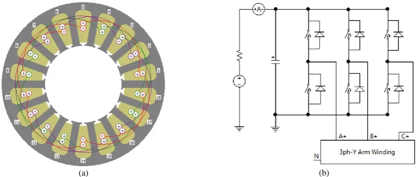
Fig. 7 Stator winding and drive circuit: a) three phase winding, b) full bridge drive circuit.
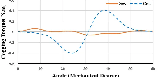
2D finite element method is applied on performance calculation of the two prototype motors, i.e., 4P-18S and 6P-18S motors. An open circuit analytical and numerical comparison of radial flux density distribution in mid-airgap diameter of 4P-18S and 6P-18S motors are shown in Fig. 8(a) and (b), respectively. A comparison of on load analytical and numerical results of tangential flux density in the investigated motors are shown in Fig. 9(a), and (b). As shown in Fig. 10(a) and (b), cogging torque waveforms are compered using analytical and numerical models. The results of analytical and numerical computation of radial and tangential components of flux density under rated load condition are shown in Fig. 11 and 12, respectively. At this condition, a comparison of electromagnetic torque and back EMF waveforms in the studied motors are compared analytically and numerically as shown in Fig. 13 and 14, respectively. The effect of magnet segmentation on cogging torque in 4P-18S motor is shown in Fig. 15.
The open circuit and on load radial components of the flux density distribution in the middle of the air gap (at r = 38 mm) are shown in Fig. 8 and Fig. 10, respectively. The effect of magnet segmentation on the radial component waveform of the flux density is clear. The effect of slot opening on the flux density waveform 2 segmented and 4 segmented topologies is very clear. However, in case of two segmented motor, the flux density waveforms distortions at the locations of the rotor slots diminished. The analytical results are in an excellent agreement with results of fine element method. It can be seen that the presented analytical model can compute the cogging torque, back-emf and electromagnetic torque with an excellent precision for
segmented surface inset topologies. Fig. 13 shows the electromagnetic torque waveforms in terms of rotor position in the surface inset topologies. At each rotor position, the current values in the different slots updated to have a sinusoidal current waveform.
5 Conclusion
An exact analytical model for performance prediction in surface inset permanent magnet machines considering slotting effects and magnet segmentation has been developed in this paper. Fourier analysis method based on sub-domain method is applied to derive analytical expressions for calculation of magnetic vector potential, magnetic flux density, cogging torque and electromagnetic torque in surface inset permanent magnet machines. This model is applied for performance computation of two prototype motors and the results of proposed model are verified by using FEM method.
Appendix
The Laplace equation can be described in quasi-Cartesian coordinate system as
1
2 2
2
2 2
1 2
ln 0
0 for
R t
A A
R
t
(33)
The general solution of (33) is obtained as (34), where n
is a positive integer.
The coefficients an, bn, cn and dn are determined
considering the continuity of magnetic vector potential between two adjacent subdomains.
1
1
2 1
0
1 2 2 1
2 1
1 2 2 1
cosh cosh
1 1
, cos
sinh sinh
cosh cosh
1 1
sin
sinh sinh
n n
n
n n
n
n t t n t t
A t a a b n
n n t t n n t t
n t t n t t
c d n
n n t t n n t t
(34)
Iranian Journal of Electrical & Electronic Engineering, Vol. 14, No. 3, September 2018 266
(a) (b)
Fig. 8 No load analytical and numerical comparison of radial flux density distribution in a) 4P-18S motor and b) 6P-18S motor.
(a) (b)
Fig. 9 No load analytical and numerical comparison of tangential flux density distribution in a) 4P-18S motor and b) 6P-18S motor.
(a) (b)
Fig. 10 Open circuit analytical and numerical comparison of cogging torque for a) 4P-18S motor and b) 6P-18S motor.
(a) (b)
Fig. 11 On load analytical and numerical comparison of radial flux density for a) 4P-18S motor and b) 6P-18S motor.
Iranian Journal of Electrical & Electronic Engineering, Vol. 14, No. 3, September 2018 267
(a) (b)
Fig. 12 On load analytical and numerical comparison of tangential flux density for a) 4P-18S motor and b) 6P-18S motor.
(a) (b)
Fig. 13 On load analytical and numerical comparison of electromagnetic torque for a) 4P-18S motor and b) 6P-18S motor.
(a) (b)
Fig. 14 On load analytical and numerical comparison of back - EMF for a) 4P-18S motor and b) 6P-18S motor.
Fig. 15 Cogging torque comparison between 4P-18S conventional (Con.) and segmented (Seg.) motors.
Iranian Journal of Electrical & Electronic Engineering, Vol. 14, No. 3, September 2018 268 References
[1] A. Jabbari, M. Shakeri and S. A. Nabavi Niaki, “Pole shape optimization of permanent magnet synchronous motors using the reduced basis technique,” Iranian Journal of Electrical and Electronic Engineering, Vol. 6, No. 1, pp. 48–55, 2010.
[2] A. Jabbari, M. Shakeri and A. S. Gholamian, “Rotor pole shape optimization of permanent magnet brushless DC motors using the reduced basis technique,” Advances in Electrical and Computer Engineering, Vol. 9, No. 2, pp. 75–81, 2009.
[3] K. Abbaszadeh, F. Rezaee Alam and S. A. Saied, “Cogging torque optimization in surface-mounted permanent-magnet motors by using design of experiment,” Energy Conversion and Management, Vol. 52, No. 10, 2011.
[4] R. Lateb, N. Takorabet and F. Meibody-Tabar, “Effect of magnet segmentation on the cogging torque in surface-mounted permanent-magnet motors,” IEEE Transactions on Magnetics, Vol. 42, No. 3, pp. 442–445, 2006.
[5] Y. J. Kim, S. S. Hwang and Y. S. Jeong, “Cogging force reduction of a stationary discontinuous armature PM-LSM by magnet segmentation,” IEEE
Transactions on Magnetics, Vol. 45, No. 6,
pp. 2750–2753, 2009.
[6] W. Y. Huang, A. Bettayeb, R. Kaczmarek and J. C. Vannier, “Optimization of magnet segmentation for reduction of eddy-current losses in permanent magnet synchronous machine,” IEEE Transactions on Energy Conversion, Vol. 25, No. 2, pp. 381–387, 2010.
[7] M. Ashabani and Y. A. R. I. Mohamed, “Multiobjective shape optimization of segmented pole permanent-magnet synchronous machines with improved torque characteristics,” IEEE Transactions on Magnetics, Vol. 47, No. 4, pp. 795–804, 2011.
[8] K. Yamazaki and Y. Fukushima, “Effect of eddy-current loss reduction by magnet segmentation in synchronous motors with concentrated windings,”
IEEE Transactions on Industry Applications,
Vol. 47, No. 2, pp. 779–788, 2011.
[9] M. Mirzaei, A. Binder, B. Funieru and M. Susic, “Analytical calculations of induced eddy currents losses in the magnets of surface mounted PM machines with consideration of circumferential and axial segmentation effects,” IEEE Transactions on Magnetics, Vol. 48, No. 12, pp. 4831–4841, 2012.
[10]H. Vansompel, P. Sergeant and L. Dupré, “Effect of segmentation on eddy-current loss in permanent-magnets of axial-flux PM machines using a multilayer-2D—2D coupled model,” in XXth International Conference on Electrical Machines
(ICEM), pp. 228–232, Sep. 2012.
[11]S. Niu, S. L. Ho, W. N. Fu and J. Zhu, “Eddy current reduction in high-speed machines and eddy current loss analysis with multislice time-stepping finite-element method,” IEEE Transactions on Magnetics, Vol. 48, No. 2, pp. 1007–1010, 2012.
[12]A. N. Marashi, K. Abbaszadeh, and F. R. Alam, “Analysis and reduction of magnet eddy current losses in surface mounted permanent magnet machines,” in 22nd Iranian Conference on Electrical
Engineering (ICEE), pp. 782–786, May 2014.
[13]M. Popescu, I. Foley, D. A. Staton and J. E. Goss, “Multi-physics analysis of a high torque density motor for electric racing cars,” in Energy Conversion Congress and Exposition (ECCE),
pp. 6537–6544, Sep. 2015.
[14]S. Spas, G. Dajaku and D. Gerling, “Eddy Current Loss Reduction in PM Traction Machines Using Two-Tooth Winding,” in Vehicle Power and
Propulsion Conference (VPPC), pp. 1–6, Oct. 2015.
[15]M. Paradkar and J. Böcker, “3D analytical model for estimation of eddy currentlosses in the magnets of IPM machine considering the reaction field of the induced eddy currents,” in Energy Conversion
Congress and Exposition (ECCE), pp. 2862–2869,
Sep. 2015.
[16]T. L. Tiang, D. Ishak, C. P. Lim and M. Kamarol, “A novel analytical method using virtual PM blocks to optimize magnet segmentations in surface-mounted PM synchronous machines,” in 18th International Conference on Electrical Machines and Systems (ICEMS), pp. 1278–1283, Oct. 2015.
[17]M. Paradkar and J. Bocker, “2D analytical model for estimation of eddy current loss in the magnets of IPM machines considering the reaction field of the induced eddy currents,” in International Electric
Machines & Drives Conference (IEMDC),
pp. 1096–1102, May 2015.
[18]S. Yang, N. J. Baker, B. C. Mecrow, D. Smith, G. Atkinson, C. Hilton, D .K. Perovic, I. Kakavas, G. Sooriyakumar and P. Harvey, “Magnet losses and demagnetisation in a permanent magnet in-wheel electric vehicle traction motor”, in International Electric Machines & Drives Conference (IEMDC),
pp. 1831–1837, May 2015.
Iranian Journal of Electrical & Electronic Engineering, Vol. 14, No. 3, September 2018 269
[19]S. T. Lundmark and P. R. Fard, “Magnet and core loss in a radial flux and a transverse flux PM traction motor,” in 10th International Conference on Ecological Vehicles and Renewable Energies
(EVER), pp. 1–9,March 2015.
[20]N. Chiodetto, N. Bianchi and L. Alberti, “Improved analytical estimation of rotor losses in high-speed PM synchronous machines,” in XXII International
Conference on Electrical Machines (ICEM),
pp. 1788–1794,Sep. 2016.
[21]M. M. J. Al-Ani and M. L. Jupp, “Switched flux permanent magnet machine with segmented magnets”, in 8th IET International Conference on Power Electronics, Machines and Drives (PEMD 2016), Glasgow, pp. 1–5, 2016.
[22]A. N. Marashi and K. Kanzi, “Thermal analysis of BLDC motor with propose new arrangement for permanent magnets to magnet eddy current loss reduction,” in 24th Iranian Conference on Electrical
Engineering (ICEE), pp. 1769–1774, May 2016.
[23]A. Jabbari, “2D Analytical Modeling of Magnetic Vector Potential in Surface Mounted and Surface Inset Permanent Magnet Machines,” Iranian Journal of Electrical and Electronic Engineering, Vol. 13, No. 4, pp. 362–373, Dec. 2017.
[24]F. M. Sargos and A. Rezzoug, “Analytical calculation of airgap magnetic field produced by inset permanent magnet rotor machine,”
J. Physics III, Vol. 1, pp. 103–110, 1990.
[25]Z. Q. Zhu, D. Howe and Z. P. Xia, “Prediction of open-circuit airgap field distribution in brushless machines having an inset permanent magnet rotor topology,” IEEE transactions on magnetics, Vol. 30, No. 1, pp. 98–107, Jan 1994.
[26]A. Rahideh and T. Korakianitis, “Analytical magnetic field distribution of slotless brushless machines with inset permanent magnets,” IEEE
Transactions on Magnetics, Vol. 47, No. 6,
pp. 1763–74, Jun 2011.
[27]T. Lubin, S. Mezani and A. Rezzoug, “Two-dimensional analytical calculation of magnetic field and electromagnetic torque for surface-inset permanent-magnet motors,” IEEE Transactions on
Magnetics, Vol. 48, No. 6, pp. 2080–2091,
Jun. 2012.
A. Jabbari is an Assistant Professor in Mechanical Engineering Department at Arak University, Arak, Iran. He obtained a B.Sc. degree in Mechanical Engineering from Iran University of Science and Technology (IUST) in 2002. He received his M.Sc. and Ph.D. degrees both in Mechanical Engineering from Mazandran University in 2004 and 2009, respectively. His research interests include renewable energy, electric machines, mechatronic systems and metal forming.
© 2018 by the authors. Licensee IUST, Tehran, Iran. This article is an open
access article distributed under the terms and conditions of the Creative
Commons Attribution-NonCommercial 4.0 International (CC BY-NC 4.0)
license (https://creativecommons.org/licenses/by-nc/4.0/).