i
tif c n
e C
i o
c n
S f
l e
a r
n e
o n
i c
t e
a 2
nr 0
et 1
1
n I
ISC 2011
Proceeding of the International Conference on Advanced Science,
Engineering and Information Technology 2011
Hotel Equatorial Bangi-Putrajaya, Malaysia, 14 - 15 January 2011
ISBN 978-983-42366-4-9
ISC 2011
International Conference on Advanced Science, Engineering and Information Technology
ICASEIT 2011
Cutting Edge Sciences for Future Sustainability
Hotel Equatorial Bangi-Putrajaya, Malaysia, 14 - 15 January 2011
SR IE AUNVI IT
NI
ES E
D K
O B
IN N
R AG
JA A
L S
A A
E N
P M
N A
A L
U A T Y
A S
S A I
REP
N I
NOI TAI COSSA STNEDUTS NA ISENOD Organized by Indonesian Students Association Universiti Kebangsaan Malaysia Proceeding of the
Effect of Rain Attenuations on Free Space Optic
Transmission in Kuala Lumpur
Fatin Hamimi Mustafa#, Abu Sahmah M Supaat*, Nachimani Charde##
# ,*
Photonic Technology Center
Faculty of Electrical Engineering, Universiti Teknologi Malaysia, Skudai, 81310 Johor
Tel.:+6012-7895870#, E-mail: [email protected]#
##
Faculty of Electrical Engineering, Nottingham University Malaysia Campus, Semenyih, 43500 Selangor E-mail: [email protected]
Abstract— This research paper describes the effects of rain attenuation on the free space optical (FSO) transmission system. The entire research was conducted in the heart of Kuala Lumpur city- year 2001, as the city was using such systems (LAN-to-LAN & WLAN-to-WLAN) widely to connect the metropolitan areas for data transmission. The preliminary experiments were done using PAVLight product modeled PL-1G/1Tx/GigE which leaded to maximum reach of 700m distance with 810nm wavelength and also laser power of 14dBm. The data for rain intensities were obtained from measuring unit at UTM Jalan Semarak, Kuala Lumpur following the ITU protocols such as ITU-R P.1814 and ITU-R P.1817. The transmission and reception were achieved by using Continuous Wave (CW) Laser signals as transmitting signals and APD photo detector to receive it on the other end. The experiments were fully carried out for two conditions (heavy-rain and lighter rain or drizzle) with multiple repetitions. At last, the collected data were compiled and compared with other researcher’s results. It was found to be the same as how the other researchers have obtained before for various cities worldwide. The results were found to be very satisfactory. It obeyed the theoretical aspects as higher the rain, higher the attenuations then. These results the degradation on the received signals. As a guide for future implementation of FSO systems for various atmospheric conditions in the metropolitan areas of Kuala Lumpur; we believed that this preliminary works may help.
Keywords— free space optical transmission system; rain attenuation; rain intensity; atmospheric conditions.
I. INTRODUCTION
Free-space optical system (FSO) refers to the transmission of modulated visible or infrared, IR beams
through the atmosphere to achieve
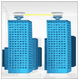
broadband communications. The theory of FSO is exactly the same as that of the fiber optical transmission system. The difference is that the energy beam is collimated and sent through clear air or space from the source to the destination, rather than guided through an optical fiber. An FSO system for the outdoor environment is workable over distances of several kilometers as far as it has clear line of sight (LOS) of atmosphere between the source and the destination [1]. Fig. 1 shows the FSO transmission link for outdoor environment using Line-of-Sight mechanism which creates links between transmitter and receiver. Although FSO systems seemed to be good solution for some broadband networking systems, it has the limitations. More significant factors are, it adaptable
to the rain, dust, snow, fog, or smog and extras. Often can block the transmission path and shut down the network due to atmospheric changes as mentioned above.
We have chosen the heart of Kuala Lumpur city as the testing location as to perform the analysis on real urban environment.
Fig.1 FSO transmission link for outdoor environment in LOS conditions between transmitter and receiver
II. RECOMMENDATION ITU-R P.1814 AND P.1817
Link margin or link budget is important issues in Free Space Optical system because it involves total loss of powers, expected received powers and transmitted powers [2]. The link margin (dBm) is given as by [6];
Mlink = Pe – Sr – Ageo – Aatmo –Asyst (1)
Where, Mlink is link margin (dB), Sr is sensitivity, Ageo is
link geometrical attenuation, Aatmois atmospheric attenuation
due to weather conditions such as rain, haze, fog and snow
and Asys represents all other system dependent losses
including misalignment of the beam direction and receiver optical losses due to beam wander.
The geometric attenuations (or geometric loss) refer to losses that occurred due to the divergence of the optical beam between transmitter and receiver [7]. For Free Space Optics propagation, the beam diverges by some amount over the path from transmitter to receiver. Geometrical attenuation equation is as [6].
( )
=
capture d geo
S S dB
A 10log10 (2)
Where, Scapture is the receiver capture surface (m2), Sd is
the surface area of transmit beam at range d, which is
approximated by [6];
(
)
24
θ
π
×= d
Sd (3)
Where, d is distance in km while θ is beam divergence in mrad.
The rain attenuation can be defined using the following
equation [6];
(4)
Where γrain is rain attenuation (dB/km), R is rain intensity
(mm/hr), k and α is rain coefficient.
The parameters ‘k’ and ‘α’ depend on the rain characteristics or can be determined from measurements. Table I shows k and α parameters values used for the estimation of the specific attenuation due to rain [6] while Table II shows the International Visibility Codes for Weather Conditions and Precipitation for rain conditions [4].
TABLE I
PARAMETERS USED FOR THE ESTIMATION OF THE SPECIFIC ATTENUATION DUE TO RAIN
Location K α
Japan 1.58 0.63
France 1.076 0.67
TABLE II
INTERNATIONAL VISIBILITY CODES FOR WEATHER CONDITIONS AND PRECIPITATION FOR RAIN CONDITIONS
Weather Condition
Precipitation Amount
(mm/hr)
Visibility
Light Fog Cloudburst &
Heavy Rain
100 770m – 1km
Thin Fog Heavy Rain 25 2km
Haze Medium Rain 12.5 2.8km – 4km
Light Haze Light Rain 2.5 5.9km – 10km
Clear Drizzle 0.25 18.1km – 20km
III.DATA COLLECTIONS
Malaysia has an equatorial climate, giving it a warm and wet weather due to its proximity to the equator that influence the rainfall at different intervals of the year [8] [9]. The rain intensity or rainfall rate data are the way to obtain the rain attenuations (from (4)) to be used in link margin equation (1). The measurement for rain intensity was done at UTM Jalan Semarak, Kuala Lumpur in 2001 as it shares the same telecommunication ID as compared with KLCC. Table III shows the rain intensity data for Kuala Lumpur and calculated the rain attenuations and also its precipitations. The rain attenuations are calculated (from (4)) with values of k and α are based on Japan location because of considering in Asian region. The Fig. 2 shows the graph of rain attenuations (dB) versus rain intensity (mm/hr) for 700m distance link from collected data of rain intensities and rain attenuations calculations.
TABLE III
RAIN INTENSITY DATA FOR KUALA LUMPUR REGION, CALCULATED RAIN ATTENUATIONS AND ITS PRECIPITATIONS
Rain Intensity (mm/hr)
Rain Attenuations for 700m distance (dB)
Precipitation
Maximum 174.49 -28.581 Heavy Rain &
Cloudburst
Minimum 1.040 -1.133 Drizzle
Rain Attenuations (dB) Vs. Rain Intensity (mm/hr) for 700m Distance 0.0000 5.0000 10.0000 15.0000 20.0000 25.0000 30.0000 35.0000 2 .4 4 1 0 .2 9 1 1 .4 7 1 3 .0 2 1 3 .9 0 1 5 .6 5 1 7 .0 7 1 8 .7 6 1 9 .7 9 2 1 .8 7 2 3 .2 9 2 6 .3 3 2 8 .5 5 3 0 .9 1 3 2 .3 7 3 4 .4 5 3 6 .9 6 3 9 .5 8 4 2 .0 8 4 5 .7 0 4 8 .7 3 5 1 .3 7 5 6 .5 0 6 0 .8 4 6 7 .4 1 7 6 .6 5 1 0 0 .6
Rain Intensity (mm/hr)
R a in A tt e n u a ti o n ( d B)
Fig. 2 The rain attenuations (dB) versus rain intensity (mm/hr) for 700m distance link
IV.OPTSIM SOFTWARE PREDICTION MEASUREMENT
A. Technical Specifications
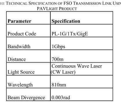
All the parameters or technical specifications are defined by standard parameters of FSO product in the market. In this project, we use the FSO transmitter and receiver from PAVLight product for optical signals transmission. Gigabit is a free space optical system designed to enable high speed communication of voice, data and video over distances up to 700m between link heads which have a clear line of sight between them. PAV Data has the worlds’ largest installed system of FSO technology, with much of it being designed and deployed by their consultants. Today PAV's FSO products are providing 1000's of connectivity solutions to both the carrier and the enterprise market across the globe [10]. PAV's comprehensive product range scales from 1.54Mbps through to 1Gbps, across distances up to 4 kilometers connecting at the speed of light.
Table IV shows the technical specification of FSO transmission link using PAVLight product [10]. However, based on the link margin equation (from (1) to (4)), there are some parameters not specified in PAVLight product, that of the values of received surface area and system loss. The selected typical value of received surface area is 180mm2 [11] while for system loss, the typical value is 6dB [12] which fulfills theoretical relationships (equation (1) to (3)).
TABLE IV
THE TECHNICAL SPECIFICATION OF FSO TRANSMISSION LINK USING PAVLIGHT PRODUCT
Parameter Specification
Product Code PL-1G/1Tx/GigE
Bandwidth 1Gbps
Distance 700m
Light Source
Continuous Wave Laser (CW Laser)
Wavelength 810nm
Beam Divergence 0.003rad
Transmit Power 14dBm
System Loss -6dB
Sensitivity -13dBm
Photodetector APD
Modulation Type Mach-Zehnder
Receive Area 0.0018m2
B. System Design
The FSO transmission link design consists of transmitter, atmosphere channel and receiver [13]. The transmitter of the FSO system is made with bit random sequence or PBRS, electrical signal generator, Continuous Wave Laser as optical source, external modulator and optical power normalize; before the signals have entered to atmosphere (channel) and then received at receiver.
Atmosphere (channel) is a transmission medium of FSO system where unpredictable weather condition such as haze and rain that cause of attenuation occurs. The present of noise also may occur in this channel that can degrade the signal performance. At receiver, it has optical receiver consists Avalanche Photodiode (APD), amplifier to amplify the weak signal and filter to remove the unwanted signal or to select the desired range of frequencies. Fig. 3 shows the FSO system transmission design using OPTsim software.
Fig. 3 The FSO system transmission design using OPTsim software
V. RESULTS AND ANALYSIS
spectrum analysis to compare the deviation between both conditions.
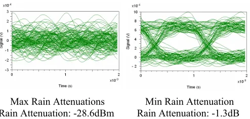
Fig. 4 shows the comparison of eye diagram between rain conditions for FSO transmission on maximum rain attenuations (heavy rain with cloudburst) and minimum rain attenuations (drizzle) for 700m distance in FSO transmission system. Eye diagram for drizzle conditions has wider eye opening compared to heavy rain conditions because of the attenuation for heavy rain is higher than drizzle conditions, -28.6dB compared to -1.3dB as mentioned earlier .
The weakness of received signal of heavy rain compared to drizzle is determined by looking the noise margin, sensitivity, timing jitter and amplitudes between both eyes diagrams [14]. The noise margin and sensitivity as compared to timing error in eye diagram for drizzle conditions is larger than for heavy rain conditions. The timing jitter of eye diagram for drizzle conditions also shows sharper than heavy rain conditions. From the eye diagram, the maximum amplitude of received signal by transmission for drizzle conditions is about 0.8mV and at the extent, the maximum amplitude for heavy rain conditions is about 0.15mV. It shows the degradation on performance of signal for transmission FSO for heavy rain conditions compared to drizzle conditions due to higher rain attenuation value for heavy rain conditions in Kuala Lumpur city.
Max Rain Attenuations Min Rain Attenuation
Rain Attenuation: -28.6dBm Rain Attenuation: -1.3dBFig. 4 Comparison of eye diagram between rain condition for FSO transmission on maximum rain attenuations (heavy rain with cloudburst) and minimum rain attenuations (drizzle) for 700m distance in FSO transmission system
The eye diagram of heavy rain conditions shows that the receive signals at receiver were distorted. It gives significant changes on the numerical values by looking at BER values. For heavy rain with cloudburst conditions, the value of BER
is 10-1 while for drizzle conditions; the BER value is 10-13.
The spectrum of frequencies of transmitted signals are observed on Fig. 5 and it shows the optical power (dBm) versus wavelength (m) of spectrum analysis for FSO transmission for maximum rain attenuations (heavy rain conditions) and meanwhile Fig. 6 shows the optical power (dBm) versus wavelength (m) of spectrum analysis for FSO transmission for minimum rain attenuations (drizzle conditions). By considering the link margin equation (from (1) to (4)), the link margin calculated for heavy rain with cloudburst conditions is -66.44dBm or 0.227nWatt, as proved in the Fig. 5. At the same time, the link margin calculated for
drizzle conditions is -39.14dBm or 121.89nWatt, as shown in
the Fig. 6.
Fig. 5 Optical Spectrum for Maximum Rain Attenuations (Heavy Rain with Cloudburst Conditions)
Fig.6 Optical Spectrum for Minimum Rain Attenuations (Drizzle Conditions)
VI.CONCLUSIONS
The performance of FSO system has been analyzed for two conditions (Heavy-Rain and Lighter Rain or Drizzle) at the heart of Kuala Lumpur in 2001. It concludes as follow:
1) Heavy rain with cloudburst had influenced the
signal strength and produced higher rain
attenuations.
2) Lighter rain is also influenced the signal strength
but produced lower rain attenuations.
3) The attenuations values for heavy rain conditions at
the heart of Kuala Lumpur city were -28.6dB.
4) The attenuations values for lighter rain conditions
at the heart of Kuala Lumpur city were -1.3dB.
5) FSO transmission at the heart of Kuala Lumpur city
in heavy rain with cloudburst conditions was
noticed to be BER 10-1.
6) FSO transmission at the heart of Kuala Lumpur city
7) FSO transmission at the heart of Kuala Lumpur city in heavy rain conditions was -66.44dBm.
8) FSO transmission at the heart of Kuala Lumpur city
in lighter rain conditions was -39.14dBm.
ACKNOWLEDGMENT
I (Fatin Hamimi Mustafa) take this opportunity to thank my supervisor, Associate Prof Abu Sahmah Mohd Supa’at for his continuous support, patience, and also unlimited ideas during the experiments. A special thank is also delivered to Ministry of Science, Technology and Innovation (MOSTI) for financial support and also to the others who helped me directly or indirectly during the analysis and also compilation of this report.
REFERENCES
[1] Roberto Ramirez, Sevia M Idrus, Ziran Sun, Optical Wireless
Communications: IR for Wireless Connectivity, 1st edition, Broken Sound Parkway NW: CRC Press, 2008.
[2] Heinz Willebrand, Baksheesh S. Ghuman, Free Space Optics;
Enabling Optical Connectivity in Today’s Network, 1st edition, Indiana, USA: Sams Publishing, 2002.
[3] Bouchet, H. Sizun, C. Boisrobert, F. Fornel, P. Favennec, Free Space
Optics - Propagation and Communication, 1st edition, Newport Beach, CA: ISTE, 2007.
[4] Propagation data required for the design of terrestrial free-space optical links, ITU-R Recommendation P.1817, 2007.
[5] Ahmed M. Mahdy and Jitender S. Deogun, “Optimizing Free Space
Optics for City-Wide Wireless Networks,” in Proceedings of the Sixth International Conference on Networking (ICN'07), 2007.
[6] Prediction methods required for the design of terrestrial free-space optical links, ITU-R Recommendation P.1814, 2007.
[7] A.K Rahman, M.S Anuar, S.A Aljunid and M.N Junita, “Study of rain
attenuation consequence in free space optic transmission,” in IEEE 6th National Conference on Telecommunication Technologies and Malaysia Conference on Photonics. 2008, pp. 26-29.
[8] (2010) Malaysian Meteorological Department Website. [Online].
Available: http://www.met.gov.my/
[9] Husagic Alma and Wajdi Al-Khateeb, “Effect of Weather Conditions
on Quality of Free Space Optic Links (with focus on Malaysia),” in IEEE, International Conference on Computer and Communication Engineering, 2008, pp. 1206-1210.
[10] (2010) PWComms for FSO PAVLight product [Online]. Available:
www.pavdata.com/en/products/
[11] G. Hansel, E. Kube, J.Becker, J. Haase and P. Schwarz, “Simulation
in the Design Process of Free Space Optical Transmission System,” in Proc. 6th Workshop Optics in Computing Technology, Paderborn,
Germany, 2003, pp. 45-53.
[12] Scott Bloom, Eric Korevaar, John Schuster and Heinz Willebrand,
“Understanding the Performace of Free Space Optics,” Jurnal of
Optical Networking, Vol 2, No 6, June 2003.
[13] G. Shaulov, J. Patel, B. Whitlock, P. Mena and R. Scarmozino.
“Simulated-Assisted Design of Free Space Optical Transmission Systems,” RSoft Design Group, Ossining. NY, pp. 1-5.
[14] Bernard Sklar, Digital Communications: Fundamental and
Applications, 2nd Edition, Upper Saddle River, New Jersey: Prentice Hall, 2001.
[15] (2005) fSona Communication Corporation. Defining a Common
Standard for Evaluating and Comparing Free-Space Optical Products. [Online]. Available: www.fsona.com/
[16] M. Al Nabousi, M. Sizun and de Fornell F, ”Propagation of Optical