Please cite this article as: F. Khakpour, G. Ardeshir, Use of a Novel Concept of Potential Pixel Energy for Object Tracking. International Journal of Engineering (IJE) Transactions A: Basics, Vol. 27, No. 7, (2014): 1023-1032
International Journal of Engineering
J o u r n a l H o m e p a g e : w w w . i j e . i r
Use of a Novel Concept of Potential Pixel Energy for Object Tracking
F. Khakpour, G. Ardeshir *
Faculty of Electrical & Computer Engineering, Babol Noushirvani University of Technology. Babol, Iran
P A P E R I N F O
Paper history:
Received 23 January 2013
Received in revised form 03 August 2013 Accepted 22 August 2014
Keywords:
Kernel-based Object Tracking, Mapping Potential Pixels Matrix
Union Image Blob
A B S T R A C T
In this paper, we propose a new method for kernel-based object tracking. Definition of union image blob and mapping it to a new representation which we named as potential pixels matrix are the main part of tracking algorithm. The union image blob is constructed by expanding the previous object region based on the histogram feature. The potential pixels matrix of union blob is used to obtain an algebraic equation for tracking the location of the kernel. We demonstrate that tracking accuracy is independent of the previous object region and it takes effect only from the expanded area of the union blob. To eliminate the background information, we propose a new method which is performed in two stages. At first, the effect of background of expanding part is reduced using a threshold distance. Then, the expanding part is divided into two parts. Tracking equations and a similarity criterion are used for each part to detect the background and target regions. We demonstrate thatthe background removing of proposed method has better performance than the mean shift tracking. Also, for better cancellation of background, the segmentation of object is used. We demonstrate the capability of the proposed method for several image sequences.
doi:10.5829/idosi.ije.2014.27.07a.03
1. INTRODUCTION1
Tracking based on regional information which is also called the kernel method, is one of the most common methods of tracking. Among the various methods in this category of tracking, the mean shift method is more taken into consideration. This is because of the simplicity in implementation and suitable speed for real-time tracking. In mean shift tracking, object information across a region is used for finding target from frame to frame. The original mean shift tracker uses a weighted histogram in rectangular or elliptic region for representing the target [1]. Maximizing the weighted histogram similarity iteratively led to the best locating match in the current frame. Some efforts have improved the performance of original mean shift by considering additional information such as spatial information, multiple features and predictive component [2-6]. Although the traditional mean shift tracking method is simple and has a good performance, but because of
1*Corresponding Author's Email: [email protected] (G.Ardeshir)
fixed kernel bandwidth with radial symmetric kernel of mean shift, it suffers from some problems such as changes in objects size or shape and the influence of background information on the target region. Fixed kernel bandwidth in classical mean shift may cause tracking failure when the object scale is changing in size during tracking. An intuitive approach of solving the scale changing is to implement the mean shift tracking with three different kernel bandwidths and choosing the size that gives the highest similarity to the target model [7]. This method has computational complexity and may not estimate object size well, because the effect of object size on scale adaptation is relatively weak and it depends only on the histogram similarity. In another approach, difference of Gaussian means shift kernel in scale space are used to solve the scale selection problem [8]. This method provides good tracking results but needs heavy computation and is not suitable for real-time. Also, different bandwidth and Gaussian kernel methods are not able to adapt to the orientation or the shape of the object. For reducing the computational complexity and orientation problems, some authors
proposed adding scale and orientation dimensions to the search space of mean shift iterations and considering object’s changes in position, scale and orientation dimensions simultaneously [9-11]. In another approach, the corner points in different periods of time are used to solve the scale problems [12]. The original mean shift tracking employs geometric shape like an ellipse or a rectangle and symmetric kernel to model the target. The target model may include the background information because the kernel shape does not always fit the object. When the background colors are similar to the target, the tracking may fail after a few frames. Many studies have attempted to solve this problem by introducing an adaptive asymmetric kernel which is constructed by a mask of detected object [6, 7, 13].
Although, significant efforts have been made to improve the tracking performance in the last decade, but all mean shift trackers have an intrinsic weakness because of iterative nature of the tracking algorithm. This weakness is related to the initial region of tracking and can be seen in other iterative methods such as contour [14-16]. At the first iteration, the candidate model is not consistent with the target region and contains the background information. For removing the background information a weighting kernel which emphasis on pixels near the center and attenuate the pixels of boundary is used in mean shift tracking. When objects are spatially adjacent or moving quickly the background information can influence the center of candidate model and it may cause tracking failure. Also, during the iteration process kernel may pass from region where contains the background similar to the object color and so can cause error in the tracking result. Furthermore, moving the kernel to reach to the best match of target model cannot detect the object changes.
Of course, the limitations of weighted kernel were taken into account in later work [17]. To solve this problem, use of background weighted histogram (BWH) was proposed in order to reduce the interference of background in target localization. In this method, the author tried to apply the weighted background coefficients in relation of tracking to reduce the probability of prominent background features in target model and target candidate model. Unfortunately, the method of BWH is not correct and it has been shown in recent work [18, 19]. In this method which is called the Corrected Background-Weighted Histogram (CBWH) algorithm, the weighted histogram is employed to reduce the prominent background features only in the target model but not in the target candidate model. In other words, even in CBWH method, the target and background are considered as a data set and the algorithm is not able to detect them separately. So, in this approach also, the emphasis is on reducing the effect of pixels that may be similar to the background. This means that the CBWH is appropriate to reduce the interference between the background and target if there
is not a considerable overlap between them.
In this paper, we proposed a new kernel-based method that uses the previous object region and histogram feature for constructing the union image blob. Mapping the union image blob to a new representation which we named it as potential pixels matrix is the core of the proposed method. The potential matrix has information about color and position of pixels. We demonstrated that this potential matrix and previous object information can be used for finding the algebraic equation of kernel location in the next frame. The union blob is achieved by the union of the estimated object in the current frame and the previous object region. Since the previous object is known, the tracking accuracy is dependent on the estimated portion of the object in the current frame. The estimated area of the union blob includes parts of the object and it may also include areas of the background. The effect of background which is in the estimated area of the union blob is eliminated in two stages. Firstly, the pixels that are most likely to belong to the background of estimated area of the union blob are removed by a distance measure. Then, the corrected area of union blob is checked for the object and background regions using tracking equations and similarity criterion. We show the background removing of proposed method has better performance than the mean shift tracking.
2.EXTRACTING UNION IMAGE BLOB
As shown in Figure 1, the union image blob can be constructed by union pixels of previous and target binary mask objects. Because the target area is unknown, an initial estimation of the target region for constructing the union blob is needed. The initial estimation of the target region can be obtained using morphological reconstruction on two images which are called mask and marker. The mask and marker regions of morphological operations are made using the binary mask of previous object and its histogram features. So, in the following, at first, the binary mask of previous region and its histogram are defined. Then, we use them to obtain mask and marker regions. The binary mask of previous frame which contains object mask with n1 pixels,
{
, P}
,i =1,2,.. . , n1,i P
i y
x is defined as:
{
}
ïî ï í ì
=
Î =
Otherwise 0 ) , ( _mask
, ) , ( if 1 ) , ( _mask
j j
P i P i j j j
j
y x P
y x y x y
x
P (1)
where (xj,yj) is the jth pixel position in R2 (image) space. The image histogram feature corresponding to the binary mask region of Equation (1) with color u, (u=1,…, m) can be defined as:
[
( )]
,u 1,2,...,m 11
= -=
å
=
n
i i
u F X u
where δ is the kroneker delta function and F(Xi) denotes the bin corresponding to the pixel at location Xi. The mask region of morphological operations must include all areas like object. Thus, all pixels in the current frame that includes the histogram of Equation (2) are considered as the mask region:
î í
ì = Î
Otherwise 0 q ) , I( if 1 ) ,
(xj yj xj yj u
M
(3)
If the marker region be a part of object region, then the morphological operation based on mask area of Equation (3) can lead to object area in the current frame. On the other hand, it is assumed for the tracking that a part of object in the current frame is in the previous area. This means that the marker region can be defined as the common region of previous object and object area in the current frame. As shown in Figure 1, the binary mask of common region based on the binary mask region of Equation (1) and (3) is:
( ) ( ) ( ) ( ) î í ì = ¹ ¹ = Otherwise 0 , 0 , , 0 , _mask if 1 , y x com y x M y x P y x com (4)
Now, the initial estimation of the target region can be obtained by morphological reconstruction of the common region (marker) of Equation (4) under the image mask of Equation (3). As shown in Figure 2, the morphological result can be affected by background pixels that are similar to the object. The process for removing the background information is described in section 3.3. After modification of the target region, the binary mask of initial estimation of the target region with m1 pixels,
{
,}
,i =1,2,.. . , m1T i T i y
x , can be defined as:
{
}
ïî ï í ì = Î = Otherwise 0 ) , ( _mask , ) , ( if 1 ) , ( _mask j j T i T i j j j j y x T y x y x y x T (5)and subsequently, the union image blob can be obtained as: ( ) ( ) î í ì = ¢ ¹ + = ¢ otherwise 0 , 0 ) , _mask( ) , _mask( if 1 , y x M y x T y x P y x M (6)
where P_mask and T_mask are defined by Equations (1) and (5). Now, we demonstrate that the object in the current frame (target) can be extracted from union image blob of Equation (6) and previous object mask of Equation (1).
(a) (b) (c)
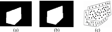
Figure 1. Constructing union image blob: (a) previous object blob, (b) target object bloband (c) union image blob, A1: previous object region (x), A2: target region (+) and A3: region belongs to both of them (·).
(d) (c) (b) (a)
Figure 2. Initial estimation of the target region: (a) previous object region, (b) candidate model, (c) common regionand(d) the morphological reconstruction of the common region.
3. THE PROPOSED METHOD FOR TRACKING THE TARGET
As shown in Figure 1, the union image blob contains information about the previous object, the target and the displacement vector of the object. Using this blob and previous object, we can obtain the displacement vector of target and subsequently formulating the target location. For achieving the target location, we proposed mapping the union blob to a new space. This mapping is used to simplify the mathematical expression that describes the relationship between the pixels of the previous object and union blob.
3. 1. Mapping Union Blob The objective of mapping is to simplify the mathematical relation for achieving the target location. The union image blob matrix of Equation (6) contains the locations of previous and target pixels. This matrix can be mapped as below which we named it potential pixels matrix.
ïî ï í ì = ¢ = = = ¢ = + = = = 0 ) , ( if 0 , 0 1 ) , ( if 1 -s , sj i , 1 . ) , ( , , , , , , j i M w a j i M w a w a j i W j i j i j i j i j i j i (7)
By this mapping, each pixel has an individual potential proportional to its position in the image blob space (in analogy with the potential of mass in the gravity of earth). The potential matrix of union blob contains the position of the previous and target pixels in the form of complex numbers. The notation of image by potential matrix is beneficial, because each pixel can be considered as a vector in image space and then, vector operations such as comparing, adding and subtracting on pixels can be applied.
3. 2. Tracking Equations Finding the displacement vector of object is the main issue of kernel-based tracking. So, we demonstrate that the displacement vector can be obtained using previous object and union blob in potential matrix space.
previous object and its corresponding pixels in target can be written as:
P ) , ( ) , ( P ) , 1 ( ) , 1 ( P ) , ( ) , ( 1 1 1 2 2 2 1 1 1 2 2 2 1 1 1 2 2 2 + + + = + + + + = + + = n l m k W n l m k W l k W l k W l k W l k W M M (8)
whereW1(i, j) and W2(i, j) are the pixel potential in the i, j position of the previous and target objects,respectively. Figure 4 shows that the union image blob in W
(potential pixels) space can be divided into two equal
q sets. Obviously, each q set contains half number of union blob pixels. Simillar toEquation (8), we can write the relation for these q sets as:
ï ï ï î ïï ï í ì + + + = + + + + = + + = ï ï î ï ï í ì + + + = + + + + = + + = P ) , ( ) , ( P ) , 1 ( ) , 1 ( P ) , ( ) , ( P ) , ( ) , ( P ) , 1 ( ) , 1 ( P ) , ( ) , ( 1 1 1 2 2 2 1 1 1 2 2 2 1 1 1 2 2 2 1 1 1 1 1 1 1 2 1 2 2 1 1 1 1 1 2 2 2 1 1 1 1 1 2 2 2 1 q q q q q q q q q q n h m g W n h m g W h g W h g W h g W h g W n l m k W n l m k W l k W l k W l k W l k W M M M (9)
whereWe1(i,j)and We2(i,j)are pixel potential in the i and
j position of the eth pixel set in the previous and target objects, respectively. By adding both sides of Equation (9), the result can be written as:
P K ) ( ) ( 1 1 , , 1
1 1 1
1 1 , , 2 2 , , 1
2 1 1
2 2 , , 1 1 2 2 +
=
å åå
å åå
= = =
= = = ijr
q r m i n j r j i r j i q r m i n j r j
i w a w
a r r
r r
(10)
where mf1, nf1 and mf2, nf2 are the fth set pixels coordinate of previous and target objects, respectively. As mentioned, the union blob is divided into two equal
q sets of pixels and then, K, the last term in Equation (10), is the half of union blob pixels. So, K can be obtained as:
åå
= = = m i n j j i a K 1 1 , 2 1 (11)where ai,j has been defined in Equation (7). With adding
) ( 1 1 , , 1
1 1 1
1 1 , , 1 1 r j i q r m i n j r j i w a r r
å åå
= = = to both sides of Equation (10), we
can write: KP -] ) ( ) ( [ ) ( 2 1 1 , , 1
1 1 1
1 1 , , 2 2 , , 1
2 1 1
2 2 , , 1 1 , , 1
1 1 1
1 1 , , 1 1 2 2 1 1 r j i q r m i n j r j i r j i q r m i n j r j i r j i q r m i n j r j i w a w a w a r r r r r r
å åå
å åå
å åå
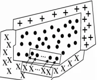
= = = = = = = = = + = ´ (12)Figure 3. Union image blob in potential matrix space
Figure 4.The temporal difference pixels in W (potential pixels) space divided into two equal q sets of pixels
The sum of the bracket terms is exactly the sum of all pixels potential in the union blob and then, the Equation (12) can be written as:
KP ) ( 2 , 1 1 , 1 1 , , 1
1 1 1
1 1 , , 1 1 -=
´
å åå
åå
= = = = = j i m i n j j i r j i q r m i n j r j
i w a w
a r r
(13)
where ai,j and w (i, j) are defined by Equation (7) and m
and n state the image blob with m´nsize. Now, from Equation (13) the displacement vector P can be obtained as: ) ( 2 K 1 1 1 , , 1
1 1 1
1 1 , , , 1 1 , 1 1 K w a w a P r j i q r m i n j r j i j i m i n j j i r r
å åå
åå
= = == =
´
-= (14)
As mentioned, the number of pixels of W1, W2 and K (Equation (11)) is the half number of union blob pixels. Therefore, the last term in the right hand side of Equation (14) can be considered as the center of previous object which we denote it by W1
m and then, we
can write: K w a W r j i q r m i n j r j i m r r )
( 1, ,1
1
1 1 1
1 1 , , 1 1 1
å åå
= = = = (15)So, the displacement vector P of Equation (14) can be obtained as: 1 m , 1 1 , 2 K 1
a w W
P m i j
i n
j j
i - ´
=
åå
= =
Again, by adding 2, , 2 1
2 1 1
2 2 , ,
2 2
( ijr
q
r m
i n
j r j
i w
a
r r
å åå
= = = ) in both sides
of Equation (10) we obtain:
KP
) (
2 ,
1 1 , 2
2 , , 1
2 1 1
2 2 , , 2 2
+ =
´
å åå
åå
= =
= = = ij
m
i n
j j i r
j i q
r m
i n
j r j
i w a w
a
r r
(17)
By dividing Equation (17) to K and introducing W2 m for
the center of target, and using Equation (16) for
substituting ij
m
i n
j j i w
a ,
1 1
,
K 1
åå
= = by 2 W
1
m+P , the
Equation (17) can be written as:
P
1 2= +
m
m W
W (18)
Equations (11), (16) and (18) are the desired equations for tracking. The center of previous objectn W1
m, can be
calculated from previous object mask. K is the half number of pixels of the union blob and it is given by Equation (11). The coefficientai,jin Equation (11) is
defined by Equation (7). Using W1
m and K, the
displacement vector P can be obtained by Equation (16). Now, the center of target,W2
m, can be computed by
substituting W1
mand P in Equation (18). The target
region can be achieved by moving the kernel window centered at W1
mto window which centered at W2m.
It should be mentioned, because of the scale and shape changes, the initial region of target can not describe the target correctly. For including the enlargement or shrinkage of the target, we can increase (+10%) the size of the initial window. Then, the target region can be achieved using the histogram feature of Equation (2) in the window of target as:
(
)
(
)
î í ì
Î
Î Î
otherwise
,
q ) , I( if arg ,
i i
u i i i
i
background y
x
y x et
t y x
(19)
The final target region can be achieved by choosing the largest 8 connected pixels at this expanded window.
3. 3. Background Removing For reducing the influence of background in mean shift tracking, a weighted kernel has been used. The function of weighted kernel is to give more weight to pixels near the color centeriod, and less weight to pixels near the border of window. The weighted kernel could not successfully reduce the background information in two cases. First, if the candidate model at first iteration has a significant amount of background information. Second, during the iteration process, the kernel passes from region which contains the background similar to the object color. Figure 5 shows the influence of background in the candidate region due to the adjacent object with similar color to the target. As shown, the weighted kernel of mean shift is not successful when the influence of background in the candidate region is
considerable. The tracking result can be unacceptable, especially if the background influences the center of candidate model.
Figure 6 shows the candidate model at first iterationwhich has no background information, but the border of object contains similar background region. The color centeriod position of this candidate model causes that in the next operation it passes from region which contains the background similar to the object color. As seen, the result of original mean shift is weak and also the asymmetric kernel method has a small error. In contrast to mean shift tracking, the accuracy of tracking Equations (16) and (18) depends on the precision of previous object and union blob pixels location. The previous object is known from previous step and then the tracking accuracy directly depends on the precision of union blob location.As shown in Figure 1, the union blob is composed of the previous object and that part of target region which has nothing in common with previous object. We named this part as non-common part of target region. Therefore, the tracking accuracy of the proposed method just depends on the non-common region. The non-common region can only be the object region, or it can be included in the object and the background.To eliminate the influence of the background on the non-common region, we propose to select two largest connected pixels of the non-common part of union blob. Then, the effect of the background is eliminated in two steps. At first, the background information of each region is decreased using distance threshold relative to the center of weighted pixels of target region. Then, a similarity criterion is used to identify whether each of these two regions are background or object.
(a) (b) (c) (d)
Figure 5.Original and asymmetric kernel mean shift tracking results when background information influenced the center of candidate model: (a) previous object region, (b) candidate model, (c) original mean shift methodand (d) asymmetric kernel method.
(a) (b) (c) (d)
As described, the accuracy of tracking depends on non-common part and the background information on the previous object region has no effect directly on the tracking formula. This is one advantage of the proposed algorithm in comparison to the mean shift method. Also, the non-common part of target region can devise other disadvantage of mean shift algorithm. Due to constancy of the kernel in mean shift method, it cannot handle non-rigid changes in the object shape. But, in the proposed method, the non-common part of union blob contains the object changes. As seen in Equation (16), applying the union blob for computing P, permits the algorithm to consider the object changes.
As mentioned in section 2, the target region is achieved by the morphological reconstruction of the common region (marker) of Equation (4) under the mask region of Equation (3). Figure 7 shows the morphological result when the background pixels lie near the boundaries of the kernel and are similar to object. As seen, the target region and subsequently the non-common part of target region include these background pixels which are connected to the actual target region.
For attenuating the effect of boundary background, we assume that the pixels near to the previous object center (candidate model) more probably belong to the target and the pixels far from it could be the influence of background.
Suppose (wmx, wmy) denotes the coordinates of
previous object center and dmax presents the largest
distance of previous object pixels from this center. Then, the center of weighted pixels of non-common part is chosen as:
) , ( ) , ( 1
Wtarget=
å
ki j wi jK (20)
(a) (b) (c) (d) (e)
(f) (g) (h) (i) (j)
Figure 7.The proposed method tracking results when background influences the edge of target: (a) previous object region, (b) candidate model, (c) common region, (d) estimation of target by the morphological reconstruction of the common region, (e) non-common region of target, (f) modified non-common region by using Equations (20) and (21), (g) background region of non common part, (h) target region of non common part,(i) tracking result of asymmetric mean shift method and (j) tracking result of proposed method.
where w(i, j) is the pixel potential in the i, j position of the non-common part and K=
å
d(i,j) is used for normalizing the pixel weight in which2
2 ( )
) ( j)
d(i, = i-wmx + j-wmy , k(i, j)=dmax-d(i, j). Now,
for Wtarget =(wtrx ,wtry) the object and background of
non-common part are separated as:
ïî ï í ì
Î
< -+ -Î
otherwise )
, (
d ) ( ) ( if target ) ,
( 2 max
background y
x
w y w x y
x
i i
y tr i x tr i i
i a (21)
where α in Equation (21) is selected 0.6 experimentally. Figure 7 illustrates the reduction of background information using Equations (20) and (21). As seen in Figure 7, the proposed method has found the correct location of target, while the asymmetric kernel approach shows a small error.
Equations (20) and (21) can successfully decrease the effect of background which influence on the edge of non-common part region and is connected to it. But as shown in Figure 8, the morphological operations on the common region which has background pixels similar to the object can produce individual background region on the non-common part of target region.
For removing the individual background information, we use the similarity value as a criterion for detecting background and object. The non-common part of target region and also two largest connected pixels of this region can be considered as three individual objects. At first, the border background effect of two objects is reduced by the method mentioned above.Then, we add the previous object region to three individual objects which the result is three union blobs. The tracking Equations (11) and (16) give the values of displacement (P1, P2, P3) of these three regions.
Now, the corresponding window of three objects can be obtained by moving previous region window as:
ïî ï í ì
= +
= +
=
+ = +
=
1,2,3 i , c
, c
r r , r
max tmax i min
tmin i
max tmax i min
tmin i
i i
i i
P c P
c
P P
r
(22)
where rmin, rmax, cmin, cmax are the vertices of previous object window and ritmin, ritmax, citmin, ctmaxi are the corresponding vertices of ith target window. Pi is the
displacement of ith target window.
Applying Equation (19) on each window of Equation (22), we obtain three target regions. Then, for
j
m1 pixels of jth target, the similarity values of previous region with individual pixel of target region can be obtain as:
1,2,3 j , m ..., 2, 1, i , otherwise 0 R
0 ) P -, P -( _ P if 1 R
j 1 j
i
j y i j x i j
i
= =
=
¹ =
S
y x mask S
(a) (b) (c) (d) (e)
(f) (g) (h) (i) (j)
Figure 8. The proposed method tracking results when background influences the center of candidate model: (a) previous object region, (b) candidate model, (c) common region, (d) estimation of target by the morphological reconstruction of the common region, (e) non-common region of target, (f) modified non-common region by using Equations (20) and (21), (g) background region of non common part, (h) target region of non common part, (i) result of asymmetric mean shift methodand (j) result of proposed method.
where P_mask is the previous object mask. The similarity values for m1j pixels of jth region (j=1, 2, 3) are:
3 2, 1, j , R Rj=
å
ij =i
S
S (24)
By selecting the region with the biggest similarity value, we can remove the background information. Figure 8 shows the power of proposed method for canceling the background information which influenced the center of candidate model. As illustrated, the result of asymmetric kernel method is not acceptable.
3. 4. Object Segmenting Equations (2), (3) and (19) show that for distinct ranges of histogram distribution of the object and background, the tracking result will have more accuracy. This means that object in which all intensity values lay within a small range will allow tracking algorithm to separate objects from the background better than the object where its grey level distribution is in a large range. Therefore, the tracking performance can be improved by segmentation of the image intensities and dividing histogram into two narrow histogram groups. In practice, the segmentation process may divide the object into more than two parts. The biggest part isassumed as the main part of tracking. The other parts can be considered or set aside as:
ïî ï í
ì > ´ >
otherwise aside set
20 & 0.1 if considered is
seg
seg base seg
seg
n
n n n
n
(25)
where nbase is the number of pixels of main part of object and nseg states the number of pixels of other parts.
3. 5. Tracking Procedure The procedure based on Equations (1) to (25) can be described as follows: Step 1. Segmenting of object in the first frame (Equation (25)).
Step 2. Set initial values of first frame: mask, histogram and window of segments (Equations (1), (2), (3)). For each segment:
Step 3. Reading current frame and finding the common region (Equation (4)).
Step 4. Estimating target region (the morphological reconstruction of the common region of Equation (4) under the imageof Equation (3)).
Step 5. Getting the non-common region and separating it into two largest connected pixels.
Step 6. Using Equations (20) and (21) for modifying two largest connected pixels of non-common region. Step 7. Getting all union blobs corresponding to two non-common region and union of them (Equation (6)). Step 8. ComputingW1
m from object of Equation (1).
Then, using Equations (16) and (18) for each union blob to obtain (P,W2
m) for each target.
Step 9. Computing each target kernel and region by using Equations (19) and (22).
Step 10. Using Equations (19) and (23) for computing the similarity value. The target corresponding to the biggest value is considered as desired target region. Step 11. Finding final target region by expanding the size of the initial window (+10%)
Step 12. Repeat Step 3 to Step 11 for all segments. Step 13. Adding all segment regions for getting final target region.
4. RESULTS AND DISCUSSIONS
The performance of proposed method algorithm is tested on several video sequences. At the beginning of tracking, an object detection method must be used to achieve the object mask. The object mask region is segmented for extraction of two narrow band histogram distributions. The comparison of proposed method with the traditional mean shift and mask object methods are presented in the experiments which are shown in Figures 9–11. The results show the superiority of the proposed algorithm in comparison with other techniques. In Figures 13 and 14 we demonstrated three experiments in order to investigate the ability of proposed algorithm for tracking the single and multiple objects in crowded and cluttered environment.
(a) (b) (c) (d) (e)
Figure 9. The candidate region with considerable background andthe tracking results:(a) target model,(b) candidate region, (c) the traditional mean shift, (d) the asymmetric kernel mean shift and(e) the proposed method.
Figure 10 demonstrates another experiment of outdoor sequences in which the boundary of target contains a large amount of background information. Because of the small background region on the candidate model, the tracking results of the original mean shift and asymmetric kernel methods are similar. The results of Figure 10 show that the proposed method has a better performance than the original mean shift and asymmetric kernel methods.
In Figure 11 we present an experiment in which the objects are close to each other and have similar color features. The tracking results demonstrate the ability of proposed method comparedtothe mean-shift algorithm and are in agreement with our expectation as discussed in section 3.2.
For better comparison of the proposed method to the mean shift tracker, the results have been shown quantitatively in Figure 12. Similar to some point-wise template trackers [20, 21], we compute the confidence value. Confidence is based on the residual error associated with the difference between the target template and the optimal region in the current frame.
) )), , ( ) , ( (( ) , ( ) , (
s r
x wx y I xy Itrg x y
T y x
res=
å
-Î (26)
where I(x,y),Itrg(x,y)denotes the gray levels of
corresponding pixels of target template and tracked region and r(h,s)=h2/(h2+s2) is the Geman-McClure error norm. w(x,y) shows the weight coefficient for the pixel and for all pixels are assumed to be equal to one. Now, the normalized measure of confidence, 0£p £1,
can be given by:
) , ( 1
) , (
å
Î-=
T y x
res
y x w x p
(27)
where the error residual,xresis normalized through dividing by
å
ÎT y x
y x w ) , (
) ,
( . Figure12 shows the confidence
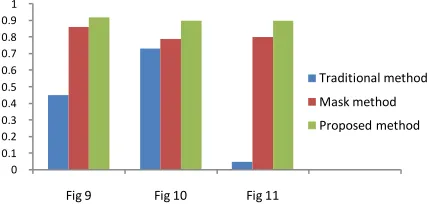
value for tracking results of Figures 9 to 11. As can be seen, if the confidence value is close to one, it means that the tracking result is more accurate. But, if the confidence value is closer to zero implies a weak tracking result
(a) (b) (c)
(d) (e)
Figure 10. Thecandidate region with a large amount of background information at the boundary of target andthe tracking results, (a) target model, (b) candidate region, (c) the traditional mean shift, (d) the asymmetric kernel mean shiftand (e) the proposed method.
(a) (b) (c) (d) (e)
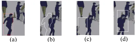
Figure 11. The candidate region with influence of background information to the center of candidate model and the tracking results:(a) target model, (b) candidate region, (c) the traditional mean shift, (d) the asymmetric kernel mean shiftand (c) the proposed method.
Figure 12.Confidence π(a) for tracking results of traditional mean shift tracker, asymmetric kernel mean shift tracker and the proposed method based on the results of Figures 9 to 11.
4. 2. Tracking Results Figures 13 and 14 demonstrate that the algorithm is successful to track the single and multiple moving objects in static and cluttered background. The single objects indoor tracking which go through translation and rotation movements are shown in Figure 13a. As shown in figure, the tracking algorithm is successful in following the target objects.The single outdoor sequences with moving waves and illumination changesare demonstrated in Figure 13b. The results of tracking show the efficiency of the proposed method. Figure14 presents the results of multiple objects tracking in complex outdoors environments with shape variation. The results of tracking show the power of algorithm for tracking the multiple objects with spatially adjacent objects in clutter environment.
0 0.1 0.2 0.3 0.4 0.5 0.6 0.7 0.8 0.9 1
Fig 9 Fig 10 Fig 11
(a)
(b)
Figure 13. Single object indoor and outdoors scenes: (a) translationand relatively rotatingindoor trackingand (b) outdoors tracking with moving waves and illumination changes.
(a)
(b)
Figure 14. Multiple objects outdoors tracking.
5. CONCLUDING REMARKS
In this paper we proposed a new method based on kernel tracking. The previous mask and the union blob are used to extract the algebraic relation of kernel movement. This is done using a novel idea that the union blob is mapped into a new representation which is called potential pixels matrix.
To overcome the problems of influence of background and object changes, we concentrated on the non-common region of union blob. The border background information of non-common region is decreased using distance threshold relative to the center of weighted pixels of this region.
The tracking relations are in algebraic form which allows us to divide the non-common region into two parts and detect the object and background regions. After cancelling the border background of non-common region for each part, the similarity value criterion is used for detecting the background and object. For each part of non-common region and union of them, the corresponding target regions are computed by applying tracking Equations. Measuring the similarity value of
each region and selecting the region with biggest similarity value is proposed for removing the background information. This method has better performance than the weighted kernel of mean shift tracking which give attention to the center of candidate model and attenuate the region near the boundary of it. For improving the tracking result, a segmentation process which divides the histogram into two narrow histogram groups is used. Furthermore, the non-common region of union blob contains the object changes and therefore the proposed method is able to consider the effect of changes in object shape. However, if the background encompasses a large area of the previous region boundaries, then the constraints for selection of non-common region may not be optimal. Research for finding the better constraints can improve the tracking result.
6.REFERENCES
1. Comaniciu, D., Ramesh, V. and Meer, P., "Real-time tracking of non-rigid objects using mean shift", in Computer Vision and Pattern Recognition,. Proceedings. IEEE. Vol. 2, (2000), 142-149.
2. Hayashi, Y. and Fujiyoshi, H., Mean-shift-based color tracking in illuminance change, in Robocup 2007: Robot soccer world cup xi., Springer, (2008), 302-311.
3. Bousetouane, F., Dib, L. and Snoussi, H., "Improved mean shift integrating texture and color features for robust real time object tracking", The Visual Computer, Vol. 29, No. 3, (2013), 155-170.
4. Wang, L., Wu, H. and Pan, C., Mean-shift object tracking with a novel back-projection calculation method, in Computer vision–
accv., Springer. (2010) 83-92.
5. Wang, J., Thiesson, B., Xu, Y. and Cohen, M., Image and video segmentation by anisotropic kernel mean shift, in Computer vision-eccv., Springer,(2004), 238-249.
6. Fan, Z., Yang, M., Wu, Y., Hua, G. and Yu, T., "Efficient optimal kernel placement for reliable visual tracking", in Computer Vision and Pattern Recognition, IEEE Computer Society Conference on, Vol. 1, (2006), 658-665.
7. Parameswaran, V., Ramesh, V. and Zoghlami, I., "Tunable kernels for tracking", in Computer Vision and Pattern Recognition, 2006 IEEE Computer Society Conference on, IEEE. Vol. 2, (2006), 2179-2186.
8. Collins, R.T., "Mean-shift blob tracking through scale space", in Computer Vision and Pattern Recognition,. Proceedings. IEEE Computer Society Conference on, IEEE. Vol. 232, (2003), 234-240
9. Yi, K.M., Ahn, H.S. and Choi, J.Y., "Orientation and scale invariant mean shift using object mask-based kernel", in Pattern Recognition. ICPR 19th International Conference on, IEEE. (2008), 1-4.
10. Quast, K. and Kaup, A., "Scale and shape adaptive mean shift object tracking in video sequences", in Proc. European Signal Processing Conference, Glasgow, Scotland. (2009), 1513-1517. 11. Yilmaz, A., "Kernel-based object tracking using asymmetric
kernels with adaptive scale and orientation selection", Machine Vision and Applications, Vol. 22, No. 2, (2011), 255-268. 12. Bi, H.-l., Yuan, B.-f. and Fu, Y., "Object tracking by mean shift
International Conference on Informatics, Cybernetics, and Computer Engineering (ICCE) Melbourne, Australia, Springer. (2012), 125-131.
13. Ning, J., Zhang, L., Zhang, D. and Wu, C., "Scale and orientation adaptive mean shift tracking", Computer Vision, IET, Vol. 6, No. 1, (2012), 52-61.
14. Bertalmio, M., Sapiro, G. and Randall, G., "Morphing active contours", Pattern Analysis and Machine Intelligence, IEEE Transactions on, Vol. 22, No. 7, (2000), 733-737.
15. Yilmaz, A., Li, X. and Shah, M., "Contour-based object tracking with occlusion handling in video acquired using mobile cameras", Pattern Analysis and Machine Intelligence, IEEE Transactions on, Vol. 26, No. 11, (2004), 1531-1536. 16. Li, W., Zhang, X., Gao, J., Hu, W., Ling, H. and Zhou, X.,
"Discriminative level set for contour tracking", in Pattern Recognition (ICPR), 20th International Conference on, IEEE. (2010), 1735-1738.
17. Comaniciu, D., Ramesh, V. and Meer, P., "Kernel-based object tracking", Pattern Analysis and Machine Intelligence, IEEE Transactions on, Vol. 25, No. 5, (2003), 564-577.
18. Ning, J., Zhang, L., Zhang, D. and Wu, C., "Robust mean-shift tracking with corrected background-weighted histogram",
Computer Vision, IET, Vol. 6, No. 1, (2012), 62-69.
19. Yang, Y., Jia, Y.X., Rong, C.Z., Zhu, Y., Wang, Y., Yue, Z.J. and Gao, Z.X., "Object tracking based on corrected background-weighted histogram mean shift and kalman filter", Advanced Materials Research, Vol. 765, (2013), 720-725.
20. Enzweiler, M., Wildes, R.P. and Herpers, R., "Unified target detection and tracking using motion coherence", in Application of Computer Vision,. WACV/MOTIONS'05 Volume 1. Seventh IEEE Workshops on, IEEE. Vol. 2, (2005), 66-71.
21. Cannons, K. and Wildes, R., Spatiotemporal oriented energy features for visual tracking, in Computer vision–accv., Springer, (2007) 532-543.
Use of a Novel Concept of Potential Pixel Energy for Object Tracking
F. Khakpour, G. Ardeshir
Faculty of Electrical & Computer Engineering, Babol Noushirvani University of Technology. Babol, Iran
P A P E R I N F O
Paper history:
Received 23January 2013
Received in revised form 03August 2013 Accepted 22August 2014
Keywords:
Kernel-based Object Tracking, Mapping Potential Pixels Matrix
Union Image Blob
هﺪﯿﮑﭼ
هدﺮﮐﻪﯾاراﻞﻧﺮﮐسﺎﺳاﺮﺑكﺮﺤﺘﻣ ءﺎﯿﺷاﯽﺑﺎﯾدرياﺮﺑﺪﯾﺪﺟشورﮏﯾﺎﻣﻪﻟﺎﻘﻣﻦﯾارد ﻢﯾا
. بﺎﺒﺣﻒﯾﺮﻌﺗ وﺮﯾﻮﺼﺗعﺎﻤﺘﺟا
ﺪﺷﺎﺑﯽﻣﯽﺑﺎﯾدرﻢﺘﯾرﻮﮕﻟاﯽﻠﺻاﺖﻤﺴﻗ،ﻢﯿﻣﺎﻧﯽﻣ ﺎﻬﻠﺴﮑﯿﭘﻞﯿﺴﻧﺎﺘﭘﺲﯾﺮﺗﺎﻣارنآﺎﻣﻪﮐﺪﯾﺪﺟﺶﯾﺎﻤﻧﮏﯾﻪﺑنآﺖﺷﺎﮕﻧ .
بﺎﺒﺣ ﻤﺘﺟا ددﺮﮔﯽﻣﻪﺘﺧﺎﺳماﺮﮔﻮﺘﺴﯿﻫﯽﮔﮋﯾوسﺎﺳاﺮﺑﯽﻠﺒﻗﯽﺷﻪﻘﻄﻨﻣشﺮﺘﺴﮔﺎﺑﺮﯾﻮﺼﺗعﺎ .
ﮏﯾندروآﺖﺳدﻪﺑياﺮﺑ
بﺎﺒﺣﻞﯿﺴﻧﺎﺘﭘﺲﯾﺮﺗﺎﻣزا،ﻞﻧﺮﮐﻞﺤﻣﯽﺑﺎﯾدرياﺮﺑيﺮﺒﺟﻪﻟدﺎﻌﻣ دﻮﺷﯽﻣهدﺎﻔﺘﺳاعﺎﻤﺘﺟا
. ﯽﺑﺎﯾدرﺖﻗدﻪﮐﻢﯿﻫدﯽﻣنﺎﺸﻧﺎﻣ
شﺮﺘﺴﮔﻪﻘﻄﻨﻣﻂﻘﻓوﺖﺳاﯽﻠﺒﻗءﯽﺷﻪﻘﻄﻨﻣزاﻞﻘﺘﺴﻣ بﺎﺒﺣزاﻪﺘﻓﺎﯾ
درادﺮﯿﺛﺎﺗنآﺮﺑعﺎﻤﺘﺟا .
ﺲﭘتﺎﻋﻼﻃاندﺮﺑﻦﯿﺑزاياﺮﺑ
دﺮﯿﮔﯽﻣمﺎﺠﻧاﻪﻠﺣﺮﻣودردﻪﮐﻢﯿﻨﮐﯽﻣدﺎﻬﻨﺸﯿﭘﺪﯾﺪﺟشورﮏﯾﺎﻣ،ﻪﻨﯿﻣز .
ﺎﺑﻪﺘﻓﺎﯾشﺮﺘﺴﮔﻪﻘﻄﻨﻣزاﻪﻨﯿﻣزﺲﭘﺮﺛا،اﺪﺘﺑارد
ﺪﺑﺎﯾﯽﻣﺶﻫﺎﮐﻪﻠﺻﺎﻓﻪﻧﺎﺘﺳآﮏﯾزاهدﺎﻔﺘﺳا
.
بﺎﺒﺣﻪﺘﻓﺎﯾشﺮﺘﺴﮔﻪﻘﻄﻨﻣ ،ﺲﭙﺳ عﺎﻤﺘﺟا
ددﺮﮔﯽﻣﺖﻤﺴﻗود .
ﯽﺑﺎﯾدرتﻻدﺎﻌﻣ
ﯽﻣفﺪﻫزاﯽﺸﺨﺑﺎﯾوﺖﺳاﻪﻨﯿﻣزﺲﭘوﺰﺟﺖﻤﺴﻗﺮﻫﻪﮐددﺮﮔﺺﺨﺸﻣﺎﺗ ﺖﺳاهﺪﺷهدﺎﻔﺘﺳاﺖﻫﺎﺒﺷرﺎﯿﻌﻣﮏﯾهاﺮﻤﻫﻪﺑ ﺪﺷﺎﺑ . ﺮﯿﯿﻐﺗﻂﺳﻮﺘﻣﯽﺑﺎﯾدرشورزاﺮﺘﻬﺑهﺪﺷﻪﺋاراشوردﺮﮑﻠﻤﻋ،ﻪﻨﯿﻣزﺲﭘﺮﺛا ندﺮﺑﻦﯿﺑزاياﺮﺑﻪﮐﻢﯾاهدادنﺎﺸﻧﺎﻣ
ﺖﺳا
.
ﺮﺑﻦﯿﻨﭽﻤﻫ ﺖﺳاهﺪﺷهدﺎﻔﺘﺳاﯽﺷيﺪﻨﺑﻢﯿﺴﻘﺗزا،ﻪﻨﯿﻣزﺲﭘﺮﺘﻬﺑفﺬﺣيا .
ﻦﯾﺪﻨﭼياﺮﺑاريدﺎﻬﻨﺸﯿﭘشورﯽﯾﺎﻧاﻮﺗﺎﻣ
ﻢﯾﺎﻫدادنﺎﺸﻧﺮﯾﻮﺼﺗﯽﻟاﻮﺗ