A NOVEL STAND-ALONE SINGLE-PHASE INDUCTION
GENERATOR USING A THREE-PHASE MACHINE AND
A SINGLE-PHASE PWM INVERTER
J. Soltani and N. R. Abjadi
Faculty of Electrical and Computer Engineering, Isfahan University of Technology Isfahan, Iran, [email protected] - [email protected]
(Received: December 24, 2002 – Accepted in Revised Form: June 25, 2003)
Abstract A new type of single-phase stand-alone induction generator using a three-phase induction
machine and a single-phase voltage-source PWM inverter is introduced. The generator scheme is capable of producing constant load frequency with a very well regulated output voltage. A small lead acid battery and a single-phase full diode-bridge rectifier are used to feed the inverter. The inverter feeds one of the stator phases. During the generator voltage build up, the inverter supplies the battery first and after a while a diode-bridge rectifier, which is fed by the generator, replaces it. The system steady state and dynamic equations are derived and are solved to obtain the performance characteristics of the generator scheme. A digital simulation study is carried out for a 2.2 KW three-phase induction machine. The simulated results obtained confirm that this generator can achieve an output power of about 0.6 pu.
Key Words Generation of Electrical Energy, Induction Motors, Modeling, Converter Control
ﻩﺪﻴﮑﭼ
ﻩﺪﻴﮑﭼ
ﻩﺪﻴﮑﭼ
ﻩﺪﻴﮑﭼ
ﺮﺗﺭﻮﻨﻳﺍ ﻚﻳ ﻭﺯﺎﻓ ﻪﺳﻦﻴﺷﺎﻣ ﻚﻳﻱﺮﻴﮔﺭﺎﻜﺑ ﺎﺑ
PWM ﻪﻟﻭﺰﻳﺍﺯﺎﻔﻜﺗ ﻲﻳﺎﻘﻟﺍﺭﻮﺗﺍﺮﻧﮊ ﻉﻮﻧﻚﻳ ،ﺯﺎﻔﻜﺗ
ﻲﻣﻲﻓﺮﻌﻣ ﺩﻮﺷ
.
ﺖﺳﺍﺖﺑﺎﺛﻥﺁﺲﻧﺎﻛﺮﻓﻭﻢﻴﻈﻨﺗﻞﺑﺎﻗﺭﻮﺗﺍﺮﻧﮊﻦﻳﺍﻲﺟﻭﺮﺧﮊﺎﺘﻟﻭ .
ﻱﺮﻃﺎﺑﻚﻳﻂﺳﻮﺗﺭﻮﺗﺍﺮﻧﮊﻦﻳﺍ
ﻳ ﻲﺟﻭﺮﺧ ﻱﺎﻬﻟﺎﻨﻴﻣﺮﺗ ﻪﺑ ﻪﻛ ﺯﺎﻔﻜﺗ ﻱﺩﻮﻳﺩ ﻞﭘ ﻩﺪﻨﻨﻛ ﻮﺴﻜﻳ ﻚﻳ ﻭ ﻚﭼﻮﻛ ﻚﺸﺧ
ﻞﺼﺘﻣ ﺭﻮﺗﺍﺮﻧﮊ ﻚ
ﻲﻣ
ﻲﻣﻚﻳﺮﺤﺗ،ﺩﺩﺮﮔ ﺩﻮﺷ
.
ﻲﻣﻪﻳﺬﻐﺗﻱﺮﻃﺎﺑﻂﺳﻮﺗﺮﺗﺭﻮﻨﻳﺍﺍﺪﺘﺑﺍ ﻮﺴﻜﻳﺎﺑﻱﺮﻃﺎﺑﻦﻳﺍﻲﻫﺎﺗﻮﻛﻥﺎﻣﺯﺯﺍﺪﻌﺑﻭﺩﻮﺷ
ﻲﻣﻦﻳﺰﮕﻳﺎﺟﻩﺪﻨﻨﻛ ﺩﺩﺮﮔ
. ﻱﺭﺎﺘﻓﺭﻱﺎﻫﻪﺼﺨﺸﻣ،ﻦﻴﺷﺎﻣﻲﻜﻴﻣﺎﻨﻳﺩﻭﻱﺭﺍﺪﻳﺎﭘﻱﺎﻬﺘﻟﺎﺣﻪﺑﻁﻮﺑﺮﻣﺕﻻﺩﺎﻌﻣﻱﻭﺭﺯﺍ
ﻲﻣﺝﺍﺮﺨﺘﺳﺍﺭﻮﺗﺍﺮﻧﮊﻢﺘﺴﻴﺳ ﺩﻮﺷ
. ﻪﻌﻟﺎﻄﻣﻚﻳﺎﺑ ﻚﭼﻮﻛﺯﺎﻓﻪﺳﻦﻴﺷﺎﻣﻚﻳﻱﺍﺮﺑﻱﺮﺗﻮﻴﭙﻣﺎﻛﻱﺯﺎﺳﻪﻴﺒﺷﻪﻳﺎﭘﺮﺑ
٢ / ٢ ﺩﻭﺪﺣ ﺭﺩﻝﺎﺼﺤﺘﺳﺍﺯﺍﻩﺪﻣﺁﺖﺳﺪﺑﺞﻳﺎﺘﻧ،ﺕﺍﻭﻮﻠﻴﻛ ٦٠
ﺩﺭﻮﻣﺍﺭﺭﻮﺗﺍﺮﻧﮊ ﻦﻳﺍﺯﺍﻦﻴﺷﺎﻣﻲﻤﺳﺍﻥﺍﻮﺗﺪﺻﺭﺩ
ﻲﻣﺭﺍﺮﻗﺪﻴﻳﺎﺗ ﺪﻫﺩ
.
1. INTRODUCTION
Single-phase induction motors can be operated as single self-regulated, self excited induction generators (SEIGs) but in general they are limited to relatively small power outputs and also have the voltage regulation weekness. For power rating above 5KW, three-phase squirrel-cage induction machines are cheaper and are more readily available hence, a recent tend has been to employ three-phase machines for single-phase (SEIG) applications [1-6].
Since last decade, the single-phase induction generators driven by prime movers such as wind and hydro-turbines, kerosene or disel engines have being considered as stand-alone sources of regulated electric power for small application requiring less
10KW where frequency regulation is not an application requirement [7].
More recently, Fukami et. al. and T.F Chan etc. all have studied the two types of single-phase SEIGs, using three-phase induction machines. The single-phase induction generator scheme reported in [5], has used a three phase induction machine Y connected to series compensation capacitors to improve the voltage regulation. Reference [6] has presented a steady-state analysis of a single-phase SEIG which employs a three-phase squirrel-cage induction machine
∆
-connected with two series and shunt capacitors. Using these capacitors, a nearly balanced operating was obtained for a certain load.suitable for commercial applications where both the regulated load-voltage or current and frequency are required. A single-phase induction generator has been presented in [7] which uses a single-phase motor and a single-phase PWM inverter. In that generator system, a lead acid battery feeding the inverter supplies real power to the generator when the load demand is greater than the power supplies by the prime mover. When the real power supplied by prime mover exceeds the load demand, the excess power charges the battery.
The above generator scheme has the following drawbacks:
a) Using a single-phase induction motor, the generator real output power therefore is limited to below the 5KW. b) A high capacity battery is required to feed the inverter hence the generator system is not economical. c) During the generator voltage biuld up, a nearly large transient current may be inrushed into the machine which cause a damage to the battery and the generator system. To come up with the above mentioned drawbacks, in this paper, a new type of single-phase stand-alone induction generator proposed which employs a three-phase star connected squirrel cage induction machine and a single-phase PWM inverter. During the generator voltage build up, a small lead acid battery is used to feed the inverter first and after while, it is replaced by a single-phase full diode-bridge rectifier. The generator supplies the rectifier itself.
2. SYSTEM DESCRIPTION
Figure 1 shows the electrical configuration of a single-phase induction generator, which uses a three-phase induction machine and a single-phase PWM inverter. As can be seen in this figure, the PWM inverter feeds the stator reference phase (
as
), here after termed the generator exciting winding. A small lead acid battery and a single-phase full diode-bridge rectifier also supply the inverter. The rectifier is connected to the stator terminals (bs
andcs
), here after termed the load terminals.Also, an inductive load with a shunt capacitor bank is connected between the stator terminals (
bs
andcs
). In addition, a conventional PI controller is also used to regulate the generator load voltage.3. SYSTEM DYNAMIC MODEL
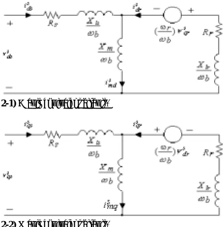
With reference to [8], the D axis and Q axis equivalent circuits of a three-phase induction machine in the stator stationary reference frame are shown in Figure 2. In this figure, all parameters are Figure 1. Electrical circuit configuration of the generator
system.
2-1) D axis equivalent circuit.
2-2) Q axis equivalent circuit.
referred to the stator and indices (s) and (r) refer to the stator and rotor quantities respectively.
The electrical parameters used in Figure 2 are defined as:
Rs
,R r
: stator and rotor resistancesX
ls,X
lr : stator and rotor leakage reactancesXm
: magnetizing reactanceω
r
: rotor angular velocityω
b : synchronous base angular velocity From Figure 2, the machine D axis, Q axis and zero sequence voltage equations are:ψ
ω
+
=
s
qs
dt
d
b
1
isqs
Rs
vsqs
ψ
ω
+
=
s
ds
dt
d
b
1
isds
Rs
vsds
(1)ψ
ω
+
=
s
os
dt
d
b
1
isos
Rs
vsos
ψ
ω
ω
−
ψ
ω
+
=
s
dr
b
r
s
qr
dt
d
b
1
isqr
R r
vsqr
ψ
ω
ω
+
ψ
ω
+
=
s
qr
b
r
s
dr
dt
d
b
1
isdr
R r
vsdr
ψ
ω
+
=
s
or
dt
d
b
1
isor
R r
vsor
(2) Also, the machine flux linkages (in volt units) are:isds
X
s
md
s
ds
=
Ψ
+
lsΨ
isqs
X
s
mq
s
qs
=
Ψ
+
lsΨ
isos
Xls
s
os
=
Ψ
(3)i sdr
X
s
md
s
dr
=
Ψ
+
lrΨ
)
4
(
i sqr
X
s
mq
s
qr
=
Ψ
+
lrΨ
i sor
X lr
s
or
=
Ψ
(4))
isdr
isds
(
Xm
s
md
=
+
Ψ
,Ψ
s
mq
=
Xm
(
isqs
+
isqr
)
(5)
One may be noted that in Equations 1-5 as well as in Figure 2, the flux linkages are expressed in terms of reactances rather than inductances. As a result the flux linkages now become flux linkages per second with the units of volts. The inductive reactances are obtained by multiplying
ω
b
times inductance [8].With reference to Figures 2 and Equations 1-5, express the load voltage
vbc
in terms ofvsqs
,vsds
,vsos
as well asias
,ibs
andics
in terms ofΨ
s
qs
,Ψ
s
ds
andΨ
s
os
, the generator performance equations are derived as:)
i
i
(
C
1
v
dt
d
cs L L+
−
=
i
L
R
L
v
i
dt
d
L LL
=
−
(6)Using the Park inverse trasformation, therefore:
]
f sqdos
[
1
2
3
2
1
1
2
3
2
1
1
0
1
]
f abcs
[
−
−
−
=
(7)Where the letter f can be either letter v (voltage) or letter i (current). Also, the superscript s denotes that the stator phase voltages or currents are transformed on to the stator stationary reference frame.
From Equatin 7, it results that
vsds
3
vbc
v
L=
=
−
vsos
vsqs
vas
=
+
(8)isos
isqs
ias
=
+
) isds ( 2 3 ) isqs ( 2 1 ics
ibs=− =− −
(9) From Equation 3
Xls smq s
qs
isqs=Ψ −Ψ ,
Xls s md s
ds
isds=Ψ −Ψ ,
Xls s os
ioos=Ψ (10)
Linking Equations 6, 9 and 10, it gives
)] X s md s ds ( 2 3 ) X smq s qs ( 2 1 i [ C 1 v dt d ls ls L L Ψ − Ψ + Ψ − Ψ + − = (11) ) X s md s ds ( 2 3 ) X s mq s qs ( 2 1 ics ibs ls ls Ψ − Ψ − Ψ − Ψ − = − = (12) Where
R
andL
are the load resistance andinductance, C is the shunt capacitor bank,
v
L andi
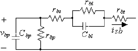
L are the load voltage and current. Note that the variables with superscript s are defined in the stator D axis and Q axis reference frame.Considering the equivalent circuit of a lead acid battery as shown in Figure 3 [7], the following equations can be derived:
r
v
isb
v
dt
d
C
bp bp bpbp
=
−
,r
v
isb
v
dt
d
C
bl bl blbl
=
−
(13)
)
r
r
(
isb
v
v
v
dc=
bp−
bl−
bs+
bt (14))]
vas
(
sign
.[
ias
isb
=
(15)Where
C
bp andv
bp are the battery capacitance and voltage respectively. The initial open circuit battery voltage isv
bpo, the self-discharging resistance isr
bp, while the capacitance and resistance simulating battery charging and discharging areC
bl andr
bl respectively.isb
is the current flowing out of the battery and output voltage isv
dc.r
bt denotes the equivalent resistance of the parallel/series battery connection. Also,sign as
(
v
)
is defined as:
<
−
>
+
=
0
vas
,
1
0
vas
,
1
)
vas
(
sign
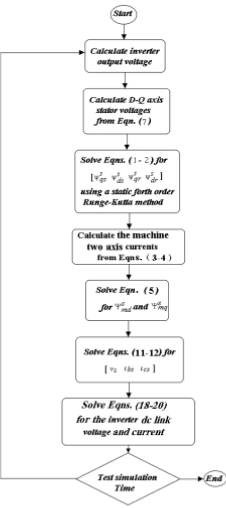
(16)Based on Equations 1-16, a C++ computer program has been developed which can be used to model the generator system of Figure 1 on a PC. The flowchart of this program is shown in Figure 4. In this program, the nonlinear differential equations are solved by a static Runge-Kutta fourth order method and variables to solve for are:
] i , v , v , v , s dr , sqr , sos , s ds , s qs [ T
x= Ψ Ψ Ψ Ψ Ψ dc bp bl L
(17) According to the configuration of Figure 1,
when the PWM inverter is switched over from the battery, and supplied from the rectifier therefore, the battery dynamic equations used in 12-14 have to be replaced by the rectifier dynamic equations given by: ) vas ( sign ]. X s os ) X smq s qs [ Cd 1 Cd id v dt d ls ls
dc + Ψ
Ψ − Ψ − = (18)
Ld
v
Ld
v
id
dt
d
=
L−
dc (19)In such situation, the varibles to solve for are:
]
id
,
i
,
v
,
s
dr
,
s
qr
,
s
os
,
s
ds
,
s
qs
[
T
x
=
Ψ
Ψ
Ψ
Ψ
Ψ
dc L(20) Where
Ld
is the rectifier filter inductance.id
andv
dc are the rectifier output current and voltage respectively.To solve the system equations, at each step ∆t of time, it is required to know the stator voltages
vsqs
,vsds
andvsos
.Starting from first iteration, assuming that:
v
)
0
(
v
)
0
(
vas
and
,
0
)
0
(
vsds
=
=
dc=
bpo (21)Therefore, from following equation
vsos
(
0
)
is also zero.Ψ
+
Ψ
ω
=
s
os
X
Rs
s
os
dt
d
1
vsos
ls b
(22)
Once
vsds
andvas
are known, then from Equation 8,vsqs
is obtained equal tov
bpo. This procedure is equally repeated for the subsequent iterations with notice to that,vas
is either+
v
dc or−
v
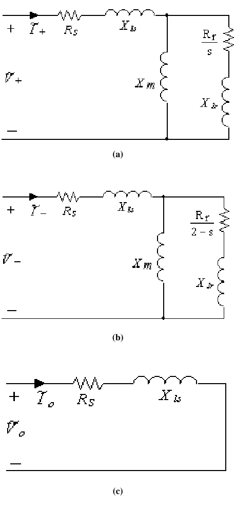
dc.4. GENERATOR STEADY-STATE MODEL
With reference to Figure 1, assume the PWM inverter is replaced for an ideal sinusoidal ac voltage source (
vas
(
t
)
) as shown in Figure 5, consider sinusoidal steady-state conditions therefore, from Figure 5:0
Y
I
~
V
~
L bs bc+ − =
I
~
I
~
cs
bs
=
−
(23)Considering the steady-state forward, backward and zero sequence equivalent models of a three-phase induction machine as shown in Figure 5, it follows that
V
~
Y
I
~
,
V
~
Y
I
~
,
V
~
Y
I
~
o o o b
f
+
−
=
−
=
=
+
I
~
o
Yo
V
~
Yb
a
V
~
Yf
a 2
I
~
bs
=
+
+
−
+
I
~
o
Yo
V
~
Yb
a 2
V
~
Yf
a
I
~
cs
=
+
+
−
+
(24)Also
V
~
o
V
~
V
~
V
~
as
=
+
+
−
+
,I
~
Yb
)
a 2
a
(
I
~
Yf
)
a
a 2
(
V
~
bc
=
−
+
+
−
−
(25)Combining Equations 24 and 25 with Equation 23, it gives = − + + − + − − − 0 0 V~as
V~ V~ V~ Y Y Y Y a a 2 a Y Y a 2 a a 2 Y 2 Y Y 1 1 1 o L o L b L f o b f (26)
V
~
Y
I
~
,
V
~
Y
I
~
,
V
~
Y
I
~
o o o b f=
−
=
−
+
=
+
(27)Where
e 3
j
2
a
=
π
(28)and
Y
f,Y
b andY
o are the forward, backward and zero sequence admitances of a three-phase induction machine at a specific negative slip ofs
,Y
L is sum of the load and shunt capacitor admitances. (V
~
+
,
V
~
−
,
V
~
o) and (~
I
+
,
~
I
−
,
~
I
o) are the three phase symetrical components of the stator voltages and currents respectively.The magnetic saturation can be modelled by the induction machine
Eg
−
Xm
curve where,Eg
is the machine airgap voltage. This curve is obtained from a synchronous test and is approximated by a piecewise linear function [5].Having known
s
andV
~
as
, Equations 26 are solved forV
~
+
,V
~
−
andV
~
o. Following to this step, the current components,~
I
+
,~
I
−
and~
I
o, are also obtained from Equation 24. In addition, the active and reactive powers (consumed by the load and generator exciting winding) can be calculated from following equations:)
I
~*
b
.
V
~
bc
Re(
P
L=
−
,Q
L=
−
Im(
V
~
bc
.
~*
I
b
)
)
I
~*
as
.
V
~
as
Re(
Pas
=
,Qas
=
Im(
V
~
as
.
~*
I
as
)
(29) (a)
(b)
(c)
5. SIMULATION RESULTS AND DISCUSSION
A digital simulation study was carried out for a 2.2KW three-phase induction machine with parameters shown in Table 1 and a
Eg
−
Xm
curve described as [5]:
<
≤ < −
≤ < −
≤ −
=
X m 19 . 32 , 0
19 . 32 X m 29 . 31 , X m 21 . 12 15 . 470
29 . 31 X m 51 . 25 , X m 31 . 3 80 . 191
51 . 25 X m , X m 92 . 1 32 . 156
Eg
(30) The simulated results of Figure 6 obtained for
Ω
=
28
.
3
R
L ,L
=
2
mH
,C
=
100
µ
F
and 03. 0
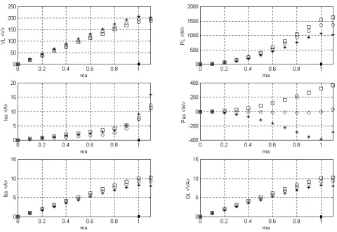
s=− . To obtain these results, a 12 volts lead acid battery is used to feed the inverter first. Then, as long as the rectifier DC voltage reaches to the level of battery voltage, the battery is disconnected and replaced for the rectifier. In addition, assuming an ideal a.c. voltage source feeding the diode bridge rectifier, the generator steady-state performance are obtained and shown in Figure 7. The results of Figure 7 demonstrate the plots of
V
L, Ibs, Ias, PL, Pas,Q
L versus the modulation index,ma
. The curves marked with (o) obtained by a load same as above and confirmthat upon the machine’s voltage and current ratings and approximately a unity power factor operation (measured at the generator load terminals included the capacitance C), approximately a real power of about 0.6 p. u. absorbed by the load while no real power is pushed into the a.c. voltage source. The plots marked with (*) and (□) obtained by
mH
2
L
=
,C
=
100
µ
F
, s=−0.03 andΩ
=
40
R
L andR
L=
22
Ω
respectively. From the second plots (marked with *), is seen that a real power of about 0.5 p. u. and 0.18 p. u. are absorbed by the load and a.c. voltage source, respectively. The third plots (marked with□) show that a real power of about 0.7 p. u. is consumed by the load, 0.55 p. u. supplied by the prime mover and the remain provided by the a.c. voltage source. From these results, it can be concluded that such a generator system could be beneficial in the remote areas where a wind or a hydro turbine can be applied and a single-phase a.c. distribution network also exists. When the load demand is greater than the power supplied by the prime mover, the single-phase a.c. line supplies the real power to the generator and when the power supplied by the turbine exceeds the load demand, the a.c. line absorbs the excess power. Because, the generator rotational and iron losses are supplied by a prime mover with constant speed therefore these losses are not taken into account in our system simulation.6. CONCLUSION
A new type of single-phase stand-alone induction generator has been introduced which employs a three-phase squirrel cage induction machine and a single-phase PWM voltage source inverter. The proposed generator scheme is a self excited self regulated generator system. The generator output frequency is always constant and is equal to the PWM inverter main frequency. In addition, the generator system has a nearly good sinusoidal output voltage and that is because of canceling out the lower order harmonics by the inverter itself as well as filtering out the higher harmonics by the three-phase machine leakage inductances. The higher amount of mechanical power injected, the higher amount of real power can be achieved. Therefore if it is necessary, a bigger three-phase machine can be employed. One may be noted that TABLE 1. Induction Machine Parameters.
Pn 2.2 kW )
(VL−L n 220
V
I n
9.1 Af
50Hz
P 4 poles R s 0.8 Ω
Rr 0.64 Ω
Ls 105.27 mH
Lr 105.27 mH
Figure 6.1. Generator voltage build up.
Figure 6.2. Dc-link voltage.
Figure 6.3. Load current waveform.
Figure 6.4. Transient waveform of the stator current.
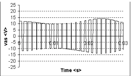
Figure 6.5. Inverter output voltage for modulation frequency factor of mf=15.
Figure 6.6. Steady-state waveform of the load voltage.
Figure 6.7. Steady-state waveform of the load instatnous power.
the generator output power has to be always tracked with the real power which is injected by the prime mover.
A 2.2KW three-phase machine has been
examined and the digital simulation results obtained show that upon the machine voltage and current ratings and approximately a unity power factor operation (measured at the generator load Figure 6.9. Battery output current. Figure 6.10. Diode bridge rectifier output current.
terminals with shunt capacitor included), a real power of about 0.6 P.U. can be achieved. Furthermore it is shown that the proposed generator system could be beneficial in the remote areas where either a hydro or a wind turbine is applicable and a single-phase distribution network is also exist. Although the paper has presented only the simulate results but this research project is continued in order to present the practical single-phase and three-single-phase test machines.
7. REFERENCES
1. Ojo, O., "The Transient and Qualitative Performance of A Self-Excited, Single-Phase Induction Generator", IEEE
Trans. On Energy Conv., Vol. 10, No. 3, (September
1995), 493-501.
2. Murthy, S. S., "A Novel Self-Regulating Single-Phase Induction Generator, Part I and II", IEEE Trans. On
Energy Conv., Vol. 8, No. 3, (September 1993), 378-388.
3. Chan, T. F., "Analysis of Single-Phase Self-Excited Induction Generator", Electric Machines And Power
Systems, Vol. 23, (1995), 149-162.
4. Rahim, Y. H. A., Alolah, A. I. And Al-Mudaiheen, R. I., "Performance of Single-Phase Induction Generator",
IEEE Trans. On Energy Conv., Vol. 8, No. 3,
(September 1993), 389-395.
5. Fukami, T., Kaburaki, Y., Kawahara, S. And Miyamoto, T., "Performance Analysis of A Regulated Self-Excited Single-Phase Induction Generator Using A Three-Phase Machine", IEEE Trans. On Energy Conv., Vol. 14,
No. 3, (September 1999), 622-627.
6. Chan, T. F.and Lai, L. L., "A Novel Single-Phase
Self-Regulated Self-Excited Induction Generator Using A Three-Phase Machine", IEEE Trans. On Energy Conv.,
Vol. 16, No. 2, (June 2001), 204-208.
7. Ojo, O., Omozusi, O., Ginart, A. and Gonoh, B., "The Operation of A Stand-Alone, Single-Phase Induction Generator Using A Single-Phase, Pulse-Width Modulated Inverter with A Battery Supply", IEEE Trans. On Energy
Conv., Vol. 14, No. 3, (September 1999), 526-531.