TECHNICAL NOTE
COMPARING OF MECHANICAL BEHAVIOR AND
MICROSTRUCTURE OF CONTINUOUS CAST AND HOT
WORKED CUZN40AL1 ALLOY
I. Ebrahimzadeh*
Department of Metallurgy and Materials, International Center for Science High Technology and Environment Sciences of Kerman
Kerman, Iran [email protected]
G. H. Akbari
Department of Metallurgy and Materials, Faculty of Engineering Shahid Bahonar University of Kerman
Kerman, Iran [email protected]
*Corresponding Author
(Received: May 24, 2007 – Accepted in Revised Form: September 13, 2007)
Abstract The performance of components produced by conventional route of a thermo mechanical process and those produced by continuous casting is interesting from different aspects of economy and technology. The performance of products in their service depends on their properties which are strongly influenced by production routes. In the present work the hardness, tensile and tensile-impact behaviors of CuZn40Al1 alloys produced by continuous casting and extrusion were investigated. Micro structural features and fracture surfaces were studied by optical and scanning electron microscopy. Results showed that wrought samples exhibited higher absorbed energy than those of continuous cast samples. Reduction of impact velocity led to a higher absorbed energy in all samples. A systematic and meaningful relationship was observed between micro structural features and mechanical properties such as hardness, yield stress and ultimate tensile strength. Fractography investigations showed that fracture occurred with dimple formation in all cases.
Keywords Continuous Caster, Cast Alloys, Wrought Alloys, CuZn40Al1 Alloys, Tensile-Impact Properties, Microstructure
ﻩﺪﻴﮑﭼ
ﻪﺘﺨﻳﺭﺪﻨﻳﺍﺮﻓﻱﺪﻴﻟﻮﺗﺕﺎﻌﻄﻗﻪﺴﻳﺎﻘﻣ ﺪﻨﻳﺍﺮﻓﻭﻪﺘﺳﻮﻴﭘﻱﺮﮔ
ﻞﮑﺷﻱﺎﻫ ﺕﺍﺰﻠﻓﻥﺩﺍﺩ
ﻪﺒﻨﺟﺯﺍ ﻱﺎﻫ ﻱﺩﺎﺼﺘﻗﺍ ﻭ
ﺖﺴﻳﮊﺭﻮﻟﺎﺘﻣﻭﻥﺎﺣﺍﺮﻃﻪﺟﻮﺗﻩﺭﺍﻮﻤﻫﻲﮑﻳﮊﻮﻟﻮﻨﮑﺗ ﺖﺳﺍﻩﺩﺮﮐﻑﻮﻄﻌﻣﺩﻮﺧﻪﺑﺍﺭﺎﻫ
. ﺭﺩﺕﺎﻌﻄﻗﻲﻳﺍﺭﺎﮐ ﺭﺎﮐﻦﻴﺣ
ﻲﻣ ﺪﻴﻟﻮﺗﺪﻨﻳﺍﺮﻓﺮﻴﺛﺎﺗﺖﺤﺗﻢﻴﻘﺘﺴﻣ ﺭﻮﻃﻪﺑﻪﮐﺩﺭﺍﺩ ﺎﻬﻧﺁ ﺕﺎﻴﺻﻮﺼﺧﻪﺑﻲﮕﺘﺴﺑ ﺪﺷﺎﺑ
. ﻪﺑﺮﺿ ﺭﺎﺘﻓﺭﻖﻴﻘﺤﺗ ﻦﻳﺍ ﺭﺩ
-ﻱﺎﻫﮊﺎﻴﻟﺁ ﻲﺘﺨﺳﻭﺶﺸﮐ،ﻲﺸﺸﮐ
CuZn40Al1
ﺭﺍﺮﻗﻲﺑﺎﻳﺯﺭﺍﺩﺭﻮﻣﻥﮊﻭﺮﺘﺴﮐﺍ ﻭﻪﺘﺳﻮﻴﭘﻱﺮﮔﻪﺘﺨﻳﺭﺵﻭﺭﻱﺪﻴﻟﻮﺗ
ﺖﺳﺍﻪﺘﻓﺮﮔ .
ﺖﺳﺍﻪﺘﻓﺮﮔﺕﺭﻮﺻﻲﻧﻭﺮﺘﮑﻟﺍﻭﻱﺭﻮﻧﭖﻮﮑﺳﻭﺮﮑﻴﻣﻪﻠﻴﺳﻮﺑﺖﺴﮑﺷﺡﻮﻄﺳﻭﻱﺭﺎﺘﺧﺎﺳﺰﻳﺭﻱﺎﻫﻲﺳﺭﺮﺑ .
ﻪﺑﺮﺿﺶﻳﺎﻣﺯﺁﺭﺩﻪﺘﺳﻮﻴﭘﻱﺮﮔﻪﺘﺨﻳﺭﻱﺎﻫﻪﻧﻮﻤﻧﻪﺑﺖﺒﺴﻧﻩﺪﺷﺭﺎﮐﻱﺎﻫﻪﻧﻮﻤﻧﺮﺗﻻﺎﺑﻱﮊﺮﻧﺍﺮﮕﻧﺎﻴﺑﺞﻳﺎﺘﻧ
-ﻲﺸﺸﮐ
ﻲﻣ ﺪﺷﺎﺑ . ﺖﺳﺍﻩﺪﻳﺩﺮﮔﻩﺪﺷﺏﺬﺟﻱﮊﺮﻧﺍﻦﺘﻓﺭﻻﺎﺑﺚﻋﺎﺑﺎﻫﻪﻧﻮﻤﻧﻡﺎﻤﺗﺭﺩﻪﺑﺮﺿﺕﺪﺷﺶﻫﺎﮐ .
ﻲﮑﻴﺗﺎﻤﺘﺴﻴﺳﻁﺎﺒﺗﺭﺍ
ﻲﮑﻴﻧﺎﮑﻣﺹﺍﻮﺧﻭﺭﺎﺘﺧﺎﺳﺰﻳﺭﻦﻴﺑ )
ﻲﺘﺨﺳﻭﻢﻴﻠﺴﺗﻡﺎﮑﺤﺘﺳﺍ،ﻲﺸﺸﮐﻡﺎﮑﺤﺘﺳﺍﺮﺜﮐﺍﺪﺣ (
ﻲﻣﻩﺪﻫﺎﺸﻣﺎﻫﻪﻧﻮﻤﻧ ﺩﺩﺮﮔ
.
ﻲﻣﻥﺎﺸﻧﺖﺴﮑﺷﺢﻄﺳﺕﺎﻌﻟﺎﻄﻣ ﻤﻳﺩﻞﻴﮑﺸﺗﺎﺑﺖﺴﮑﺷﺎﻫﻪﻧﻮﻤﻧﻪﻴﻠﮐﺭﺩﻪﮐﺪﻫﺩ
ﺖﺳﺍﻩﺩﺍﺩﻱﻭﺭﺎﻫﻞﭙ .
1. INTRODUCTION
The Continuous casting process has been employed
the past century [1-3]. In continuous casting, molten metal from a holding furnace is fed into a water cooled mold in which the solidification process occurs and solidified metal is taken out from the mold at the same time [4]. This means that in the process, melting, solidification and outgoing of the product occur simultaneously [2,5]. The casting system consists of a primary water cooled mold and a water sprayed system or water pool as a secondary cooling stage [6]. Molten metal is fed continuously into the system which is solidified by a cooling system [4]. The metallic shell should be thickened enough before it leaves the mold to withstand the hydrostatic pressure of remaining molten metal [4,5]. The solidified shell is drawn out at a constant speed by a mechanical system from the mold and it is water sprayed to complete the solidification outside of the mold [4]. Continuous cast products are relatively cheaper than those produced by thermomechanical processes [1,2], but their metallurgical properties and dimensional precisions are lower [1]. Considering the advantages of continuous cast products including lower costs [4,5], if their metallurgical and mechanical properties are acceptable, this method can replace other manufacturing processes. Therefore, understanding the process and its parameter is very useful and essential. Progress in this field has led to replacement of many continuous cast components which had been manufactured by conventional thermo mechanical routes [2,3]. Various components from copper, aluminum and steel in the form of plate, strip, rod, tube and sections are produced by this method [8].
CuZn40Al1 is a double phases high strength brass recently produced by the continuous casting process [9].This alloy has been conventional
produced by a thermo mechanical method by extrusion for a relatively long time [10,11]. The presence of alloying elements such as Al, Mn, Si and Fe increases the strength. In the present work microstructure and tensile behavior of continuous cast products of the above material have been investigated and compared with those of the same material produced by thermo mechanical processing.
2. MATERIAL AND EXPERIMENTS
2.1. Material
Continuous cast components ofCuZn40Al1 produced by Zochen Company in Mashhad and extruded components produced by Semi-finished copper product company in Kerman of the same material were used in the present work. Compositions of the materials are shown in Table 1. The compositions are slightly different but they are recognized as the same material in the market, as also having the same uses. The zinc coefficient [14] is 44.87 percent for cast material and 44.81 percent for the wrought type.
2.2. Tensile-Impact and Tensile Tests
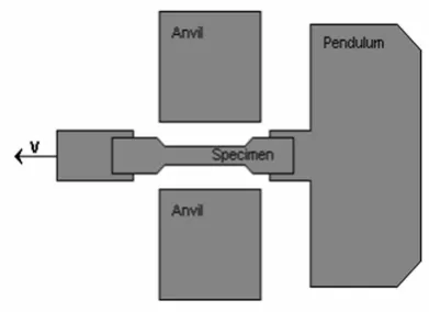
Tensile-impact specimens were prepared as shown in Figure 1. The longitudinal direction of the samples was along the casting direction and extrusion direction in these kinds of material. Each test was repeated three times. Specimen surfaces were polished by 1200 and 4000 grinding paper. The tests were done at speeds of 5×10⁻⁵, 3.11, 4.15
and 5.23 m/s. Low speed tests were performed by Instron tensile machine while high speed tests were done by Roller-Amsler PK450 tensile-impact pendulum, which could be set for different angles to attain suitable impact speeds (Figure 2).
TABLE 1. Chemical Analysis of the Materials used in the Present Investigation, in wt %.
Element Cu Zn Pb Fe Mn Ni Al Si Sn
Cast 58.1 33.868 1.4 1.71 1.45 0.171 1.35 0.091 0.496
2.3. Compression Test To investigate the elastic
behavior and measure elastic modulus of the materials, compression tests were also carried out. Specimens with 12 mm diameter and height to diameter ratio of 1.5 were used.
2.4. Hardness Measurements The hardness of
specimen was measured by an Instron Volpert instrument in Vickers unit. At least 5 measurements were done for each sample and average values were reported.
2.5. Metallographic and Microscopic
Observations
Microstructures and fracturedsurfaces of the samples were investigated by optical and scanning electron microscopes. Samples for micro structural observations were polished by grinding paper and subsequently by diamond paste 0.25 μm. They were etched in a solution of 20 ml acetic acid + 10 ml 5 % Cr2O3
solution + 5 ml of FeCl3 10 % solution + 100 ml of
distilled water [9]. Some samples were electro polished and electro etched in a solution of 20 %
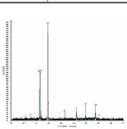
phosphoric acid. The microstructures were studied by optical microscope equipped with an image analyzer, enabling it to determine the fraction of phases and porosities. The XRD technique was employed to identify phases in both cast and wrought samples.
3. RESULTS AND DISCUSSION
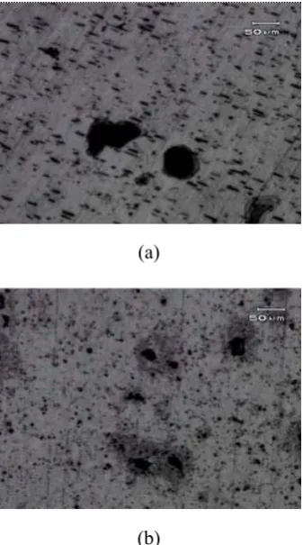
Table 2 shows the results of tensile-impact tests of both continuous cast and wrought samples. Results show marked differences between the two kinds of materials. Wrought samples absorb more energy to fracture than those of continuously cast material. Porosities and shrinkage cracks in the cast material may lead to a lower energy for fracture. Figure 3 illustrates typical porosities in the materials. The quantitative data related to porosities and their shape characteristics are presented in Table 3. Number and volume fractions of porosities in the cast material are larger than those in the wrought material. It is difficult to determine the fraction of spherical porosities in the wrought material but the majority of them do not have sharp corners. But porosities in the cast material have generally sharp corners. Round porosities are the result of gas entrapment, while shrinkage discontinuities have sharp corners. It is believed that thermo mechanical processing improved mechanical behavior through omitting of shrinkage cracks and voids as well as improving the microstructure [13]. In cast material, shrinkage discontinuities lead to stress concentration and impair tensile and impact resistances, especially at higher strain rates. Another difference between the two materials is the presence of γ-phase in the cast material which
Figure 1. Configration of specimen (dimensions are in mm).
Figure 2. The details of pure tensile-impact anvil.
TABLE 2. Absorbed Energies in Tensile-Impact Test for Different Materials and Pendulum Angles.
Pendulum Angle 150° 100° 70°
Cast (J) 100.1 102.865 107.665
was not detected in the wrought material. X-ray diffraction patterns of the two materials are illustrated in Figures 4 and 5. The existence of brittle γ-phase in the cast material may cause a lower impact resistance and energy for fracture. With an increasing pendulum angle, in other words increasing impact speed, absorbed energy for fracture decreases in both materials, which exhibits the effect of strain rate on the fracture behavior of the materials.
Stress-strain curves of the two materials are shown in Figure 6, and extracted data from the curves are presented in Table 4. An obvious difference is observed between the elastic modulus of the two materials. To investigate the above phenomenon some samples of the materials were prepared and their stress-strain relationships in the elastic range were obtained by a compression test. Results of the compression test are illustrated in
Figure 7. The same difference is observed which means the difference is related to materials not the test procedure. The elastic modulus of the cast material, resulted from tensile test, is 100 GPa. In the case of the wrought material elastic modulus is 75 GPa. The above difference may be attributed to the differences between the microstructures of the two materials. The amount, morphology and distribution of phases and also textures, which is subjected to more investigations, may lead to different behaviors of the two materials.
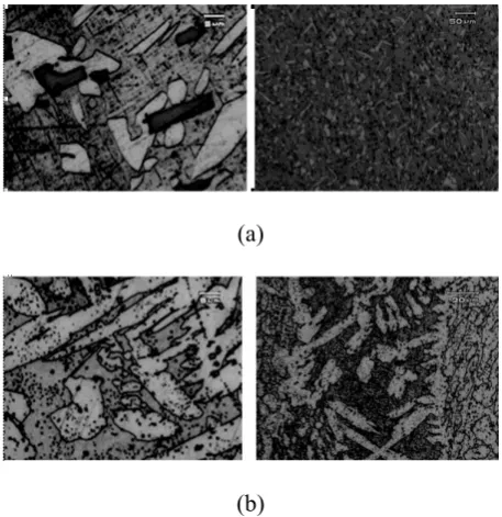
Results show marked differences between tensile characteristics of the two materials. Yield strength of the wrought material is 539 MPa and that of cast material is 295 MPa. Their ultimate tensile strengths are 488.6 MPa for cast material and 690 MPa for wrought material. Results are consistent with previously reported values for similar material [14]. The surface area under stress-strain curve, which is a measure of absorbed energy for fracture per unit volume, is markedly larger in the wrought material. On the other hand work-hardening coefficient in the cast material is obviously bigger than that of wrought material. The observed differences in mechanical characteristics are definitely related to the differences in their microstructures and also structural defects resulted from the two different manufacturing processes. These differences include grain size and morphology [15], amount and distributions of phases [16,17], as well as defects such as voids, cracks and porosities [10]. Manufacturing processes have profound effects on microstructure, defects and consequently on the mechanical properties which are obvious in two materials of the present study. Figure 8 illustrates the microstructures of the two materials. In both cases α and β phases together with precipitates are observable. The α-phase, in the cast material shows more directionality resulted from solidified structure, with sharper edges and corners. Table 5 presents the fractions of α phase in both materials which is larger in the cast material.
On the other hand, higher yield strength in the wrought material is attributed to finer and more homogeneous microstructure resulted from thermo mechanical processing. Coarser structure in the cast material resulted in higher strain hardening coefficient and lower ultimate strength. In the stress-strain curves, necking is not obvious but (a)
(b)
Figure 3. Porosities in microstructure (a) cast material (b)
there is a little decrease in stress levels in the case of wrought material before fracture. The absence of necking, in fact, is related to the significant fraction of β-phase in both materials and also to solidification defects in the cast material, which promote the fracture process. The differences in the microstructures of the two materials are also reflected in their harnesses (Table 6). In the cast material with coarser microstructure and more α -phase fraction the hardness is lower. As inferred from Figure 6, the cast material shows a more slightly elongation than the extruded one, which seems a little strange. It should be noted that the α -fraction in the cast material is 52 % while in the wrought material it is 25 % (Table 5). α-Phase has fcc structure that is more formable than β-phase
with bcc structure. This difference may be responsible for more elongation. This matter should be investigated in future works.
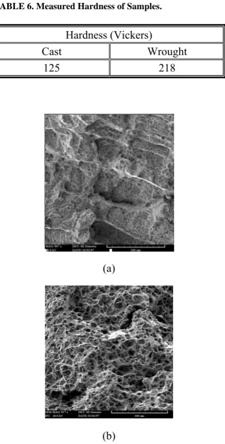
Fractography of fractured surfaces by SEM showed ductile fracture with dimple formations for all samples (Figure 9). In the cast material some structural defects caused the initiation of cracks (Figure 9b). In wrought samples the fracture surfaces are more homogeneous and dimples are finer, which are consistent with higher impact resistance in the material.
At higher strain rates, dimples become finer and their numbers increase. This means that at higher strain rates finer defects can be the origin of initiation and propagation of cracks leading to fracture.
TABLE 3. Type and Amount of Porosities in Samples.
Round Fraction Number % Round Fraction Volume % Total Porosity %
Cast 13.52 11.75 1.54
Wrought 14.8 2.27 1.2
4. CONCLUSIONS
• Distinct differences are observed between
microstructures and fractions of porosities of the two materials. The horizontal cast material contains more porosities and defects.
Figure 5. Diffraction pattern of wrought material.
Wrought
Cast
Figure 6. Tensile-stress strain curves of hot worked and continuous cast CuZn40Al1 alloys.
TABLE 4. Mechanical Properties of the Present Material.
E (GPa) Yield (MPa) UTS (MPa) El % n K
Cast 100 295 488.6 15.5 0.4613 1581.25
• The differences in mechanical properties of the materials are consistent with their microstructure differences.
• Absorbed energy of fracture for horizontal continuous cast material is less than that of wrought material.
• Yield stress and ultimate tensile strength in the wrought material are larger.
• The cast material surprisingly showed more elongation in tensile test which should be investigated in future works.
5. ACKNOWLEDGEMENTS
The authors wish to acknowledge the financial support of the International Center of Science and High Technology and Environment science Kerman.
6. REFERENCES
1. Schliefer, H., Khoury, A., Porten, M., Wolber, P., Boller, K. H., Durrschnabel, W., Muller, H. R., Muller, W. H., Schwarze, M., Oelmann, H., Rode, D. and Frankenberg, R., “Remarks about Process and Technology of continuous Casting, Proceeding of the International congress on Continuous casting of Non-Ferrous Metals”, Continuous casting, Edited by Muller, H. R., (14-16 November 2006), 51-70.
2. Sommerhofer, H., and Sommerhofer, P., “New Continuous casting Process, Proceeding of the International congress on Continuous casting of Non-Ferrous Metals”, Continuous casting, Edited by Muller, H. R., (14-16 November 2006), 368-377.
3. Muller, W. and Scheneider, P., “Horizontal casting Technology for copper Products”, Proceeding of the International congress on Continuous casting of Non-Ferrous Metals”, Continuous casting, Edited by Muller, H. R., (14-16 November 2006), 329-335.
(a)
(b)
Figure 7. Stress-Strain relationships in elastic range for the
two materials (a) tensile test (b) compression test.
(a)
(b)
Figure 8. Microstructures on transverse sections of (a)
4. Brey, M., “Horizontal continuous casting of copper Alloy Billets”, International congress”, Continuous casting, Edited by Ebrke, K. and Schneider, W., (13-15 November 2000), 325-332.
5. Plochikhine, V., Karkhin, V. and Bergmann, H., “Grain structure, Microstructure and texture of Copper Ingots Produced During the continuous casting Process”, International congress: Continuous casting, Edited by Ebrke, K. and Schneider, W., (13-15 November 2000), 109-114.
6. Uoti, M. and Immonen, M., “Theoretical and Experimental Study of Vertical Continuous Casting”, International congress: Continuous casting, Edited by Ebrke, K. and Schneider, W., (13-15 November 2000), 143-148.
7. Slamova, M., Karlik, M., Robaut, F., Slama, P. and Veron, M., “Deffrences in Microstructure and texture of Al-Mg Sheets produced by twin-roll Continuous casting and by direct-chill casting”, Materials
Characterization, Vol. 49, (2003), 231-240.
8. Spinelli, J. E., Tosetti, J. P., Santos, C. A., Spim, J. A. and Garica, A., “Microstructure and solidification termal parameters in the thin strip continuous casting of a stainless steel”, Jou. of Mat. Pro. Tech., Vol. 150,
(2004), 255-262.
9. Sakaguchi, Y., Maruyama, T., Kobayashi, T., “Effect of cooling rate on β Phase fraction of Cu-Zn Alloy”, Jou.
of the JRICu, Vol. 43, (2004), 31-35.
10. Mapelli, C. and Venturini, R., “Dependence of mechanical properties of an α/β on the Micro structural features induced by hot Extrution”, Scr. Mate., Vol. 54,
(2006), 1168-1173.
11. Ridley, W. N., “Microstructure and Wear of some High Tensile Brasses”, J. Mat. Sci., Vol. 29, (1994),
1692-1699.
12. Sakaguchi, Y., Maruyama, T. and Kobayashi, T., “Effect of Si Content and cooling rate on β Phase fraction of Cu-Zn Alloy”, Jou. of the JRICu, Vol. 43,
(2004), 36-41.
13. Henkel, D. and Pense, A. W., “Structure and property of engineering materials”, Mc Graw-Hill, (2002), 307-317. 14. Davis, J. R., “Copper and copper alloys”, ASM
International Handbook, (2001), 35-47.
15. Li, Z., Samuel, A. M., Samuel, F. H., Ravindran, C., Valtierra, S. and Doty, H. W., “Parameters controlling the performance of AA319-type alloys Part I. Tensile properties”, Mat. Sci. and Eng. A, Vol. 367, (2004),
96-110.
16. Fatahalla, N., Hafiz, M. and Abdulkhalek, M., “Effect of microstructure on the mechanical properties and fracture of commercial hypoeutectic Al-Si alloy modified with Na, Sb and Sr”, Jou. of Mat. Sci., Vol.
34, (1999), 3555-3564.
17. Cao, H. and Wessen, M., “Effect of microstructure on Mechanical properties of as-cast Mg-Al Alloys”, Meta.
And Mat. Tran. A, Vol. 25A, (2004), 309-315.
18. Shabestari, S. G. and Shahri, F., “Influence of modification, solidification conditions and heat treatment on the microstructure and mechanical properties of A356 aluminum alloy”, J. Mat. Sci., Vol. 39, (2004), 2023-2032.
19. Turhal, M. S. and Savaskan, T., “Relation between secendary dendrite arm spacing and mechanical properties of Zn-40Al-Cu alloys, J. Mat. Sci., Vol. 38,
(2003), 2639-2646.
TABLE 5. Volume Fraction of α-Phase in the Microstructure.
Wrought Material Cast Material
α % 24.728 52.436
TABLE 6. Measured Hardness of Samples.
Hardness (Vickers)
Cast Wrought 125 218
(a)
(b)