Please cite this article as: H. Moradi Cheshmehbeigi, A. Khanmohamadian, Design and Simulation of a Moving-magnet-type Linear Synchronous Motor for Electromagnetic Launch System, International Journal of Engineering (IJE), TRANSACTIONS C: Aspects Vol. 30, No. 3, (March 2017) 351-356
International Journal of Engineering
J o u r n a l H o m e p a g e : w w w . i j e . i rDesign and Simulation of a Moving-magnet-type Linear Synchronous Motor for
Electromagnetic Launch System
H. Moradi Cheshmehbeigi*, A. Khanmohamadian
Electrical Engineering Department, Faculty of Engineering, Razi University, Kermanshah, Iran
P A P E R I N F O
Paper history: Received 18 July 2016
Received in revised form 15 October 2016 Accepted 05 January 2017
Keywords:
Electromagnetic Aircraft Launch System Permanent Magnet Linear Synchronous Motor
Halbach Shaped Magnets Finite Element Analysis
A B S T R A C T
The Electromagnetic Aircraft Launch System (EMALS) offers significant benefits to the aircraft, ship, personnel, and operational capabilities. EMALS has such advantages as high thrust, good controllability, reusable, etc., as a launching motor, a double-side plate Permanent Magnet Linear Synchronous Motor (PMLSM) can provide high instantaneous thrust. This paper presents the design and analysis of the moving-magnet-type permanent magnet linear synchronous motor (PMLSM). A detailed analytical modeling based on Maxwell’s equations is presented for analysis and design of PMLSM with Halbach array. In order to improve the thrust characteristics of PMLSM, the structural characteristics and magnetic field are analyzed. The results show an enhancement in the motor performance. Finally, we have used 2-D nonlinear time-stepping transient finite element method to demonstrate validity of the analytical analysis and parametric search is used for multi-objective optimization of PMLSM. Using Finite Element Analysis (FEA), the effects of the parameters on the thrust and thrust ripple waveforms are analyzed.
doi: 10.5829/idosi.ije.2017.30.03c.04
1. INTRODUCTION1
The Electromagnetic Aircraft Launch System (EMALS) is the US Navy’s next generation aircraft launching system for the twenty first century aircraft carriers. EMALS will greatly enhance the operational capabilities of the carrier by expanding the performance envelope over the current launch system to handle aircraft at a much wider range of launch speeds and energies. This new launch system will be more efficient, controllable, and will reduce the weight, volume, and total ownership cost from the current steam catapult system [1]. One of EMALS most important benefits to the ship is the increased flexibility in the layout of the launch system components. This allows greater optimization of the ship’s internal arrangement including better load distribution. The elimination of steam dependence allows a more optimal and efficient ship power plant design. In essence, EMALS opens up
1*Corresponding Author’s Email: [email protected] (H. Moradi
Cheshmehbeigi)
the trade space for both naval architects and aeronautical engineers in designing the future Navy [2]. EMALS is a complete launch system designed to replace the existing steam catapult. The basic design consists of an energy storage/power generation subsystem, a power conditioning subsystem, a launch motor, and a control system. These subsystems combine to provide a highly capable launch system that expands the operational capability of future carriers to allow for heavier, faster aircraft, and, in addition, permits the operation of small, lightweight air vehicles that are currently not compatible with the steam catapult [3].
rule are necessary to promote performance for PMLSM design.
In recent years, PMLSM have been proven to provide the best all-around performance for EMALS applications in comparison to induction-type motor because of their high force, and high efficiency [5].
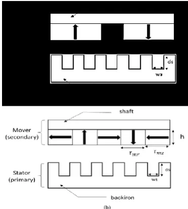
The double-sided plate PMLSM has been paid more and more attention for the EMALS. For the double-sided plate motor, the two-double-sided normal forces counteract each other, so it can avoid the impact of a unilateral magnetic pull [6]. The basic structure of a moving-magnet type of a Double-Sided PMLSM is shown in Figure 1.
The structural model of PMLSM is composed of permanent magnets (PMs) in secondary and coil winding with slotted stator in long primary. A Radial array, which is a special case of PM motors, is less used for PMLSM applications because of its high ripple force production. In order to reduce thrust ripple and increasing flux density, the optimized quasi-Halbach magnetized topology can be applied to the PMLSM [7].
Quasi-Halbach topology has a self-shielding property and higher flux density than Radial topology.
Figure 1. Basic Structure of a Moving-Magnet type Double-Sided PMLSM.
Figure 2. PMLSM topologies. (a) Radial array, (b) Quasi-Halbach array.
In this paper, a PM mover with quasi-Halbach topology is proposed to replace the radial topology for PMLSM. Figure 2 shows a Topology of PMLSM (a) radial array, and (b) quasi-Halbach array, both motors having identical stators.
Due to the different magnetization direction of permanent magnet on two sides, there are two types of magnetic circuits: parallel magnetic circuit (PMC) and serial magnetic circuit (SMC), as shown in Figure 3.
PMC- PMLSM has a moving-magnet type secondary, which is composed of double-sided permanent magnets arranged by N face N direction, while the SMC- PMLSM is composed of double-sided permanent magnets arranged by N face S direction. Usually, the PMC- PMLSM is adopted because it can generate a larger thrust and a smaller thrust ripple than the other [8].
2. ELECTROMAGNETIC FIELD MODEL ANALYSIS
Figure 4 shows the simplified diagram of two dimensional solution area for PMLSM. To calculate the flux density in the air-gap, the symmetry boundary conditions between permanent magnet is set. The permanent magnet region, air gap region, and slotted stator region are divided in turn along the y-axis direction with three boxes alveolar layers boundary. The moving-magnet mover could only slip along the x-axis direction [9].
The distribution equations of magnetic field for each layer are given as follows:
𝜕2𝐴
𝐼
𝜕𝑥2 +
𝜕2𝐴
𝐼
𝜕𝑦2 = 0 ; 𝑅𝑒𝑔𝑖𝑜𝑛 𝐼 (1)
(a) (b)
Figure 3. Two types magnetic circuit (a) PMC, (b) SMC
𝜕2𝐴 𝐼𝐼
𝜕𝑥2 +
𝜕2𝐴
𝐼𝐼
𝜕𝑦2 =
𝑗𝑣𝑥
𝜋
𝜏(𝑛 − 1)𝜎𝑚𝜇𝑚𝐴𝐼𝐼− 𝜇0𝐽𝑚 ; 𝑅𝑒𝑔𝑖𝑜𝑛 𝐼𝐼
(2)
𝜕2𝐴
𝐼𝐼𝐼
𝜕𝑥2 +
𝜕2𝐴
𝐼𝐼𝐼
𝜕𝑦2 = 𝑗𝑣𝑥
𝜋
𝜏(𝑛 − 1)𝜎𝑠𝜇𝑠𝐴𝐼𝐼𝐼 ; 𝑅𝑒𝑔𝑖𝑜𝑛 𝐼𝐼𝐼 (3)
where, A is the curl of magnetic vector; 𝜎𝑠 and 𝜎𝑚,
denote the conductivity of permanent magnet and iron yoke respectively; 𝜏 denotes the pole pitch; 𝑣𝑥 denotes
the velocity of mover along the x-axis direction; n is the multiple of the space harmonics to fundamental field. 𝐽𝑚
is derived from equation (4).
𝐽⃗𝑚= ∇ × 𝑀⃗⃗⃗ = 𝐵𝑟/𝜇0𝑒𝑗(𝜔0𝑡−𝑎𝑡) (4)
where, 𝐵𝑟 is the remanence of permanent magnet, and 𝜔0 is the equivalent angular velocity. Magnetic obtained
out of position and the winding currents, according to Ampere's law, the mover thrust have been suffered as equation (5).
𝐹⃗𝑡ℎ𝑟𝑢𝑠𝑡= ∫ 𝐽⃗ × 𝐵𝑉 ⃗⃗𝑑𝑉= ∫ 𝐽⃗ × (𝑖
𝜕𝐴
𝜕𝑥+ 𝑗
𝜕𝐴
𝜕𝑥)𝑑𝑉
𝑉 (5)
The thrust ripple ratio 𝐹𝑟𝑖𝑝𝑝𝑙𝑒 is defined as:
𝐹𝑟𝑖𝑝𝑝𝑙𝑒=𝐹𝑡ℎ𝑟𝑢𝑠𝑡
𝑚𝑎𝑥 −𝐹
𝑡ℎ𝑟𝑢𝑠𝑡𝑚𝑖𝑛
𝐹𝑡ℎ𝑟𝑢𝑠𝑡𝑎𝑣 (6)
where, 𝐹𝑡ℎ𝑟𝑢𝑠𝑡𝑚𝑎𝑥 , 𝐹𝑡ℎ𝑟𝑢𝑠𝑡𝑚𝑖𝑛 , and 𝐹𝑡ℎ𝑟𝑢𝑠𝑡𝑎𝑣 denote the
maximum, minimum, and average values of the thrust in a computation period, respectively.
However, the results of this method were not accurate, since the non-linear magnetic flux leakage has not been taken into account. Also in computing thrust, the effect of stator slot is not intended. Because thrust density is the most important metric that shows the rationality of the magnetic circuit parameters. Therefore, the analytical expression for PMLSM analysis is summarized in this parameter.
One of the most important drawbacks of PMLSM is the thrust ripple. So, in this paper one of the objective functions is the minimization of the thrust ripple. Another important subject in PMLSM is maximization of the average thrust. Since this improvement may cause an increase in permanent magnet volume which leads to an increase in the cost of the motor. So that, we chose the ratio of the average thrust to the PM volume as the second objective function. At least, a multi-objective optimization is discussed and both thrust ripple and thrust density are improved. The constraints are maximum flux density in teeth (Bmax) and maximum
current flow (imax). The parameters affecting force ripple
and thrust force are selected as design variables and other parameters are selected as fixed variables. The design variables and ranges of the values are listed in Table 1.
3. MODEL OF FINITE-ELEMENT ANALYSIS
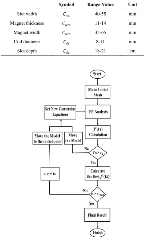
The parametric search is used for multi-objective optimization of PMLSM. The method was made in a 2D
FEA software for a displacement of the translator of a polar step and with 10 steps of time (TS) of the simulation and the chosen values of TS are:
[1/10τs, 1/5τs, 3/10τs, 2/5τs, 1/2τs, 3/5τs, 7/10τs, 4/5τs, 9/10τs and τs].
The thrust and ripple for each step of time are a mean value of the data obtained for simulation, with a displacement of a polar and is given by:
𝐽𝑇𝑠𝑐 = 𝑘1∗ (𝑚𝑎𝑥{|𝐹𝑟𝑖𝑝𝑝𝑙𝑒(𝑇𝑠0)|})2+ 𝑘2∗
1
(𝐹𝑡ℎ𝑟𝑢𝑠𝑡(𝑇𝑠0))2
, 𝑓𝑜𝑟 0 ≤ 𝑇𝑠0≤ 𝜏𝑠 (3)
k1 and k2 are weight functions. In the studied case, an equal weight of 1 is given to both functions, since maximization amplitudes of thrust is as important as thrust ripple diminishing, c is range value of parameters, step of value change is shown with ic . A flowchart of the FEA is shown in Figure 5.
TABLE 1. Nominal values of the geometrical parameters of the PMLSM.
Symbol Range Value Unit
Slot width 𝐶𝑤𝑠 40-55 mm
Magnet thickness 𝐶𝑤𝑚 11-14 mm
Magnet width 𝐶𝑤𝑚 35-65 mm
Coil diameter 𝐶𝑑𝑠 8-11 mm
Slot depth 𝐶𝑑𝑐 18-21 cm
4. SIMULATION
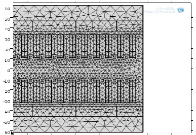
Figure 6 shows the meshed model of PMLSM by FEA. It can be seen that magnets, drive coil and tooth are relative intensive so as to ensure the accuracy of simulation.
The magnetic-flux-line for PMLSM is shown in Figure 7. It is observed that the magnetic-flux-line in PMC-PMLSM is parallel and the magnetic circuit structure is complex, uniform with low flux leakage.
5. OPTIMIZATION
Figure 8 and Figure 9 show the thrust and the thrust ripple results under different widths of the vertical magnetized magnet respectively, where design variables are divided in seven values for full range. The results indicate that the thrust increases as the width of the PM varies, but the rate slows down and tends to saturate, the amplitudes of thrust of PMLSM as follow the higher amplitude obtained for the width of PM=55 mm and the minimum thrust ripple ratio of PMLSM are 1% for the width of PM=55 mm.
Figure 10 and Figure 11 show the thrust and the thrust ripple results under different thicknesses of the PM, respectively.
Figure 6. The triangular meshed model of PMLSM by FEA
Figure 7. The flux linkage distribution for PMLSM
The results indicate that the thrust increases as the thickness of the PM varies, the maximum thrust of PMLSM are 12530 N for the thickness of PM=14 mm, and the thrust ripple ratio reaches a minimum at 12 mm.
Figure 8. Result of Thrust based on step of time (TS) considering width of the PM (cwm)
Figure 9. Thrust ripple ratio with different widths of PM.
Figure 10. Result of thrust based on step of time (TS) considering thickness of the PM (chm)
The impact analysis of the coil diameter is very important for estimating the actual performance. The responses of the thrust and the thrust ripple ratio with different coil diameters are shown in Figure 12 and Figure 13, respectively. The thrust is increased according to the increase of coil diameter, but coil diameter is limited by current constraint. These variables have the optimum value of minimizing the thrust ripple and maximizing the thrust force.
Figure 14 and Figure 15 show the thrust and the thrust ripple results under different slot depths (𝑐𝑑𝑠),
respectively. The results indicate that the thrust increases as the slot depth varies, but the rate slows down and tends to saturate, the amplitudes of thrust of PMLSM as follow the higher amplitude obtained for the slot depth =20 mm.
Figure 12. Result of Thrust based on steps of time (TS) considering coil diameter (𝑐𝑐𝑑)
. Figure 13. Thrust ripple ratio with different coil diameters
Figure 14. Result of Thrust based on steps of time (TS) considering slot depth (cds)
Figure 15. Thrust ripple ratio with different slot depths.
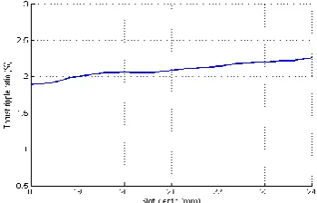
But the minimum thrust ripple ratio of PMLSM are 5% for the slot depth =18 mm. Figure 16 and Figure 17 show the thrust and the thrust ripple results under different widths of slot (𝑐𝑤𝑠), respectively. The thrust is
increased according to the increase of width of slot, but width of slot is limited by flux density constraint, the amplitudes of thrust of PMLSM as follow the higher amplitude obtained for the width of slot =50 mm. but the minimum thrust ripple ratio of PMLSM are 3% for the width of slot =40 mm.
Table 2 lists the values of optimized design variables and fixed variables. By design optimization, the normalized force ripple is reduced 8.7% and the thrust force is increased 12.84 N compared to those not using the design optimization.
Figure 16. Result of Thrust based on steps of time (TS) considering slot width (cws)
TABLE 2. Optimized design variable and fixed variable
Symbol Value Unit
Magnet width 𝐶𝑤𝑚 55 mm
Magnet thickness 𝐶ℎ𝑚 13 mm
Coil diameter 𝐶𝑑𝑠 0.11 mm
Slot depth 𝐶𝑑𝑐 20 cm
Slot width 𝐶𝑤𝑠 55 mm
Pole pitch 𝜏 60 mm
Slot pitch 𝜏𝑠 10 mm
Residual flux density 𝐵𝑟 1.2 T
Air gap length g 3.5 cm
Rated current 𝐼𝑚 420 A
6. CONCLUSIONS
In this paper, a modest attempt has been done to discuss a design for a double-sided PMLSM in EMALS. An analysis based on Maxwell’s equations was derived to predict air gap magnetic flux density distribution and thrust force. Based on the results, this paper establishes the finite element method and analyzes the effects of the parameters on the thrust and thrust ripple performance for EMALS. Many important design and installation guides can be acquired. The design of quasi-Halbach array magnet configuration helps in achieving high thrust force and uniform flux density along the air gap of the PMLSM, thereby reducing thrust force ripple.
7. REFERENCES
1. Bushway, R.R., "Electromagnetic aircraft launch system development considerations", IEEE transactions on magnetics, Vol. 37, No. 1, (2001), 52-54.
2. Doyle, M.R., Samuel, D.J., Conway, T. and Klimowski, R.R., "Electromagnetic aircraft launch system-emals", IEEE transactions on magnetics, Vol. 31, No. 1, (1995), 528-533. 3. Patterson, D., Monti, A., Brice, C.W., Dougal, R.A., Pettus,
R.O., Dhulipala, S., Kovuri, D.C. and Bertoncelli, T., "Design and simulation of a permanent-magnet electromagnetic aircraft launcher", IEEE Transactions on Industry Applications, Vol. 41, No. 2, (2005), 566-575.
4. Kou, B., Huang, X., Wu, H. and Li, L., "Thrust and thermal characteristics of electromagnetic launcher based on permanent magnet linear synchronous motors", in Electromagnetic Launch Technology, 2008 14th Symposium on, IEEE. Vol., No. Issue, (2008), 1-6.
5. Huang, L., Yu, H., Hu, M. and Liu, H., "Study on a long primary flux-switching permanent magnet linear motor for electromagnetic launch systems", IEEE Transactions on Plasma Science, Vol. 41, No. 5, (2013), 1138-1144.
6. Kim, C.-E., Lee, S.-H., Lee, D.-H. and Kim, H.-J., "The analysis of permanent magnet double-sided linear synchronous motor with perpendicular arrangement", IEEE transactions on magnetics, Vol. 49, No. 5, (2013), 2267-2270.
7. Seok-Myeong, J., Sung-Ho, L. and In-Ki, Y., "Design criteria for detent force reduction of permanent-magnet linear synchronous motors with halbach array [j]", IEEE transactions on magnetics, Vol. 38, No. 5, (2002), 3261-3263.
8. Kou, B., Wu, H. and Li, L., "The thrust characteristics investigation of double-side plate permanent magnet linear synchronous motor for eml", in Electromagnetic Launch Technology, 2008 14th Symposium on, IEEE. Vol., No. Issue, (2008), 1-5.
9. Ng, K., Zhu, Z. and Howe, D., "Open-circuit field distribution in a brushless motor with diametrically magnetised pm rotor, accounting for slotting and eddy current effects", IEEE transactions on magnetics, Vol. 32, No. 5, (1996), 5070-5072.
Design and Simulation of a Moving-magnet-type Linear Synchronous Motor for
Electromagnetic Launch System
H. Moradi Cheshmehbeigi, A. Khanmohamadian
Electrical Engineering Department, Faculty of Engineering, Razi University, Kermanshah, Iran
P A P E R I N F O
Paper history: Received 18 July 2016
Received in revised form 15 October 2016 Accepted 05 January 2017
Keywords:
Electromagnetic Aircraft Launch System Permanent Magnet Linear Synchronous Motor
Halbach Shaped Magnets FEA
ديكچ ه
( یسیطانغمورتکلا هباترپ یاهمتسیس
EMAL
تیزم ) .تسا هدرک هضرع لااب یتایلمع تیلباق اب یتشک ،امیپاوه یارب ار ییاه
یاهمتسیس
EMAL
هصخشم لرتنک ،لااب شنار نوچمه ییاه و بوخ یریذپ
هرهب اب ار ددجم هدافتسا تیلباق یاهروتوم زا یریگ
هدرک مهارف مئاد سیطانغم یطخ نورکنس و یحارط هلاقم نیا رد .دنا
لیلحت هدافتسا دروم مئاد سیطانغم یطخ نورکنس یاهروتوم
ب لوسکام تلاداعم ساسا رب یلیلحت یزاسلدم نینچمه .تسا هدش هیارا یسیطانغمورتکلا هباترپ یاهمتسیس رد راتخاس یار
PMLSM
یسیطانغم نادیم یطخ روتوم راتخاس ،ورین هصخشم دوبهب تهج همادا رد .تسا هدش هیارا خابلاه لیلحت
.تسا هدش
لدم قیدصت تهج نایاپ رد .دهدیم ناشن ار هدش هیارا راتخاس ییاراک دوبهب ،لیلحت نیا زا هدمآ تسدب جیاتن زا یلیلحت یزاس
ءازجا شور سا یدعب ود دودحم راتخاس دوبهب یارب یرتماراپ دنچ یزاس هنیهب شور کی زا نینچمه و تسا هدش هدافت
PMLSM
زا هدافتسا اب .تسا هدش هتفرگ هرهب لیلحت
ءازجا یدیلوت یورین هنماد رب یحارط یاهرتماراپ ریثات دودحم یسررب
.تسا هدش