98
Copyright © 2017. Vandana Publications. All Rights Reserved.
Volume-7, Issue-6, November-December 2017
International Journal of Engineering and Management Research
Page Number: 98-102
Design of Low Power Tunable OTA-C Filter for Biomedical Applications
K.Chandra Sekhar1, Dr. M.Mahesh2
1
M. Tech., Department of Electronics & Communication Engineering, Universal College of Engineering and Technology, Guntur, INDIA
2 Professor, Department of Electronics & Communication Engineering, Universal College of Engineering and Technology, Guntur, INDIA
ABSTRACT
A novel CMOS continuous time integrated mixed notch and low pass filter is designed for multi standard biomedical applications like ECG, EMG, EEG etc. i.e a single device can be used to monitor multiple bio medical signals. In biomedical signal processing the power line signal (50Hz/60Hz) has to be suppressed with notch filter and remaining low pass band has to be allowed through low pass filter. In this work both notch filter and low pass filter is combined in one schematic. In order to get power line notch filter of 50 Hz and low pass filter of cutoff frequency less than 1 kHz, A Novel Bulk driven Operational Trans Conductance Amplifier (OTA) is used with 0.5V supply in CMOS 130 nm Technology. The transconductance value of proposed OTA is less than 1 nS. In this paper the notch filter of sixth order attained notch depth of 75 dB with 280 nW power consumption and low pass filter of fourth order consumes around 200 nW power.
Keywords— ECG signal, EMG, Notch filter, Operational Trans Conductance Amplifier (OTA), Biomedical
I.
INTRODUCTION
Now a day’s scope of biomedical circuits is increasing tremendously. Basically any biomedical system consists of following building blocks like electrodes, pre-amplifiers, biomedical filters followed by ADC [1]. Basically the
biomedicalsignalsECG(electrocardiogram),EEG(Electroence phalography), EMG( Electromyography) etc., all are having very small amplitude around few millivolts and very low frequency below 1KHz.
Fig. 1. Block diagram of biomedical signal processing system
Fig.1 shows the biomedical processing system. It is clear that all bio medical signals consist of very low amplitude with very low frequencies up to 1 kHz [3]. Hence in order to avoid different individual biomedical signal filtering, one can design a simple multi standard biomedical filter for all signals like ECG, EEG or EMG etc. This paper presents a novel multi standard biomedical filter with ultra low power. A notch filter (50/60Hz) [4], [5] has to be needed to avoid power line interface with information signal as it is easily pick up by electrodes.
99
Copyright © 2017. Vandana Publications. All Rights Reserved.
II.
OPERATIONAL
TRANSCONDUCTANCE AMPLIFIER
DESIGN
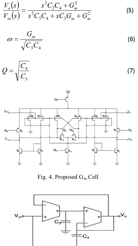
In this paper to implement different low pass and notch filters a OTA is used which is designed for ultra low power and low frequency (around 100 Hz) applications. Hence the transconductance value Gm should be very low. In order to get low Gm value, bulk driven OTA schematic is used as shown in Fig. 4. All the transistors used in this OTA are operated in weak inversion (sub threshold) region of operation and while tuning those can be used in saturation region also. Because of wide tuning range and weak inversion region we can attain very low power consumption and bulk driven is chosen to give low Gm value of the order of 50 nS. M1 and M2 transistors are two PMOS transistors to which inputs are given to the bulk terminals. M3 and M4 are NMOS transistors and biased to dc voltage of Vb2 to act as constant current source. Wherea s PMOS transistors M6 and M7 are used as negative resistance to improve the gain of the output response. Finally t h e transistor M5 and resistors R1 and R2 are act as local common mode feedback of OTA. In this paper 0.5 V supply is used hence the input common mode and output common mode voltages have to be adjusted to half of supply voltage i.e 0.25V. Common mode voltages at outputs can be adjusted by R1 and R2. However by using OTA shown in Fig. 4 can
be used to tune from 50 nS to 100 nS. Means the minimum value of Gm value with this OTA is only 50 nS. But in order
to get 50 Hz notch Gm value should be very small. Hence in
order to reduce Gm value further a proposed transconductor
is designed.
A. Proposed Operational Transconductance Amplifier The bulk driven OTA shown in the Fig. 4 can be tuned only from Gm value of 50 nS to 100 nS. In order to reduce
Gm value below 1 nS a bulk driven current deviation OTA
with local common mode feedback is proposed in this paper which is shown in the Fig. 3. By using this approach Gm
value can be scale down to 10 to 20 times of original Gm
value. In this proposed OTA, except M13, M14 transistors all
other transistors are operating in weak inversion region to consume low power. The input is given to PMOS transistors M3, M1 and M2, M4 where (W/L) of M1 is less than that of
M3 similarly M2 is less than that of M4. For local common
mode feedback PMOS transistors M13, M14 are operated in
triode region to give a tunable resistance. NMOS transistors M5, M7 and M6, M8 pairs act as constant current mirror. The
minimum Gm
The capacitor multiplier working is based on the principle of scaling the impedance or admittance from the required port. As capacitance increases, impedance across the capacitor reduces and for particular voltage it will pass more current [5]. This is the basic idea of capacitor multiplier.
Here more current is produced for same voltage, that leads to decrease in impedance and thereby large capacitance is achieved. Capacitor multiplier allows considerable reduction in the area but at the expense of more power. The basic idea of capacitor multiplier using current amplifier is as shown in the fig2
value by this proposed OTA is around 0.1 nS.
B. Capacitor Multiplier
Fig. 2. Capacitance Multiplier
III.
MIXED NOTCH - LOW PASS FILTER
DESIGN
A. Low pass filter design
In this paper low pass filter and notch filter can be design with similar schematic with a change of input supply positions. With a single ended supply and with two Gm
( )
( )
1 22 1 21 2 1 2 m m m m m in o
G
G
G
sC
C
C
s
G
G
s
V
s
V
+
+
=
cells a second order low pass filter can be designed as shown in Fig. 4 and with added extra supply a second order notch filter can be designed with the same schematic as Shown in Fig. 3. The response is given by the following equations.(1)
( )
( )
21 2 1 2 2 m m m in o
G
G
sC
C
C
s
G
s
V
s
V
+
+
=
(2)
C
1C
2G
mc
=
ω
(3)1 2
C
C
Q
=
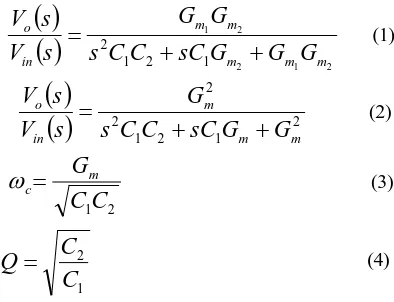
(4)Equation 1 represents the transfer function of second order low pass filter which is shown in the Fig. 3 Since both the Gm cells are identical Gm1 = Gm2 (1) can be
100
Copyright © 2017. Vandana Publications. All Rights Reserved.
B. Notch filter design
As described in the above subsection Fig. 5 shows the schematic of second order notch filter. The equations for the Transfer function, Cutoff frequency (Notch frequency) and Quality Factor are as shown below.
( )
( )
23 4 3 2
2 4 3 2
m m
m
in o
G
G
sC
C
C
s
G
C
C
s
s
V
s
V
+
+
+
=
(5)
4 3
C
C
G
m=
ω
(6)3 4
C
C
Q
=
(7)Fig. 4. Proposed Gm
Fig. 5. Second order notch filter Cell
Equation 5 represents the transfer cell function of second order notch filter similarly (6) gives notch frequency and (7) gives Quality factor of notch filter.
C. Mixed Notch-Low pass filter design
Since for any biomedical signal from the electrode can be interference with the power line (50/60 Hz) signal, so attenuation of (50/60 Hz) is necessary for all biomedical applications.By using second order notch filter the depth of notch is only around 20 dB - 30 dB. Since this much attenuation is not sufficient for biomedical processing, a sixth order notch filter is designed by cascading three second order notch filters shown in Fig. 6. Similarly a fourth order butter worth low pass filter is designed by cascading two similar second orders LPF. This mixed filter (sixth order notch and fourth order low pass) is designed by using just ten Gm cells. The Q factors of notch filter and low pass filter has
to be same as it is connected in cascade. So in order to give resultant Q factor of 0.707 (butter worth) the capacitance values of C1, C2, C3 and C4
Fig. 6. Cascading of Sixth order Notch filter and forth order low pass filter
are adjusted without exceeding 10 pF.
IV.
RESULTS
In this paper with using proposed OTA a sixth order notch filter and fourth order low pass filter are designed and cascaded to give combined notch low pass response. The different performance plots are shown in the following figures. In this paper single ended Gm cell are used to design
low pass and notch filters. The Gm value for notch filter is
fixed to 0.8 nS and the Gm value of low pass filter is variable
because of this paper is designed for multi standard biomedical applications like ECG, EEG, and EMG etc. As described earlier the low pass filter of fourth order is designed with using just four Gm cells which will save the
power. The fourth order low pass filters can be tuned by using different bias current values. The variable magnitude response low pass filter of different Gm values is shown in
the fig.7. The magnitude response of sixth order Gm-C notch
101
Copyright © 2017. Vandana Publications. All Rights Reserved.
response of this mixed notch and low pass is shown in the Fig. 11. In order to compare this paper results with the literature survey, two different comparison tables are given individually i.e Table II for notch filter comparison and Table III for low pass filter comparison with the existing technologies.
Fig. 7. Magnitude response of LPF
Fig. 8. Magnitude Response of sixth order Notch Filter
Fig. 9. Phase Response of Notch Filter
Fig. 10. Magnitude Response of Mixed Notch - Lowpass Filter
Fig. 11. Phase Response of Mixed Notch - Lowpass Filter
TABLE I. COMPARISON TABLE FOR NOTCH FILTER WITH LITERATURE SURVEY
Parameter Ref[4] Ref[3] Ref [2] Ref[14] Propose d work
Vdd(V) 1 1 1.8 1.5 0.5
Tech. (nm) 180 180 180 180 130
Zerofreq(Hz 250 50-250 29-71 40-80 50-60
Notchdep.d - 50 55 78 75
Order 5 5 5 4 6
Structure Gm-C Gm-C opamp opamp OTA-C Power (nW) 453 458 25000 300 280
THD(dB) -48 -48 -53 -65 -68
App ECG ECG ECG ECG,EEG,
EMG
ECG,EE G, EMG
TABLE II. SUMMARY AND COMPARISONS OF LOWPASS FILTER FROM THE LITERATURE
SURVEY
Parameter Ref[9] Ref[10] Ref[12] Ref[13] Praposed work
102
Copyright © 2017. Vandana Publications. All Rights Reserved.
Tech.(nm) 180 800 180 180 130
Bandwidth(H z)
2.4 2000 1M 100 100-1000
(tunable)
Order 6 6 4 2 4
Structure Gm-C Gm-C Gm-C Gm-C OTA-C Power 10µW 2.5µW 36uW 225nW 200nW
THD(dB) -60 -40 -58 -60 -62
DR(dB) 60 70 54 75 73
V.
CONCLUSION
This work presents a novel design of OTA for implementing power line notch filter (50Hz/60Hz) and variable low pass filter with minimum cut-off frequency of 100 Hz and maximum cut-off frequency of 1 kHz for bio potential acquisition systems. After a lot of literature survey this paper has lead to a new approach avoiding demerits of other works with improved characteristics. In this paper a novel bulk driven current sharing Operational Trans conductance Amplifier with local common mode feedback is designed for ultra low power and frequency applications. The total power consumption of the two filters (notch and low pass) is around 480 nW with 0.5 V supply. The Dynamic Range of fourth order low pass filter is 73 dB. Experimental results show significant improvement in power, linearity and total harmonic distortion
REFERENCES
[1] H. A. Alzaher, N. Tasadduq and Y. Mahnashi, "A Highly Linear Fully Integrated Powerline Filter for Biopotential Acquisition.Systems," in IEEE Transactions on Biomedical Circuits and Systems, vol. 7, no. 5, pp. 703-712, Oct. 2013. [2] H. Li, J. Zhang and L. Wang, "A fully integrated continuous-time 50-Hz notch filter with center frequency tunability," 2011Annual International Conference of the IEEE Engineering in Medicine and Biology Society, Boston, MA, 2011, pp.3558-3562.
[3] Su, Yu-Cheng, Huan Chen, Ching-Lun Hung, and Shuenn-Yuh Lee. "Wireless ECG detection system with low-power analog front-end circuit and bio-processing ZigBee firmware." In Circuits and Systems (ISCAS), Proceedings of 2010 IEEE International Symposium on, pp. 1216-1219. 2010.
[4] Lee, Shuenn-Yuh, and Chih-Jen Cheng. "Systematic design and modeling of a OTA-C filter for portable ECGdetection." Biomedical Circuits and Systems, IEEE Transactions on 3, no. 1 (2009): 53-64.
[5] S. Y. Lee and C. J. Cheng, "Systematic Design and Modeling of a OTA-C Filter for Portable ECG Detection," in IEEE Transactions on Biomedical Circuits and Systems, vol. 3, no. 1, pp. 53-64, Feb. 2009.
[6] Qian, Xinbo, Yong Ping Xu, and Xiaoping Li. "A CMOS Continuous-time low-pass notch filter for EEG systems." Analog Integrated Circuits and Signal Processing
44.3 (2005): 231-238.
[7] Ramakrishnan, Shubha, Paul E. Hasler, and Christal Gordon. "Floating gate synapses with spike-time-dependent plasticity." Biomedical Circuits and Systems, IEEE Transactions on 5.3 (2011): 244-252.
[8] Corbishley, Phil, and Esther Rodriguez-Villegas. "A nanopower bandpass filter for detection of an acoustic signal in a wearable breathing detector." Biomedical Circuits and Systems, IEEE Transactions on 1.3 (2007): 163-171.
[9] Solís-Bustos, Sergio, et al. "A 60-dB dynamic-range CMOS sixth-order 2.4-Hz low-pass filter for medical applications." Circuits and Systems II: Analog and Digital Signal Processing, IEEE Transactions on 47.12 (2000): 1391-1398.
[10] Rodriguez-Villegas, Esther, Alberto Yúfera, and Adoracion Rueda. "A 1.25-V micropower Gm-C filter based on FGMOS Transistors operating in weak inversion." Solid-State Circuits, IEEE Journal of 39.1 (2004): 100-111. [11] Qian, Xinbo, Yong Ping Xu, and Xiaoping Li. "A CMOS continuous-time low-pass notch filter for EEG systems." Analog Integrated Circuits and Signal Processing 44.3 (2005): 231-238.
[12] Vasantha, M. H., and Tonse Laxminidhi. "0.5 V, Low Power, 1MHz Low Pass Filter in 0.18 µm CMOS Process." In Electronic System Design (ISED), 2012 International Symposium on,pp.33-37. IEEE, 2012.