Volume 2, Issue 9, September 2013
Page 117
ABSTRACT
The sub synchronous Resonance (SSR) is a significant problem in power system having a steam Turbine – Generator connected to a series compensated transmission system. Flexible AC transmission systems (FACTS) controllers are widely applied to mitigate SSR. In this paper, the use of FACTS controllers such as Gate controlled series capacitor (GCSC), Unified power flow controller (UPFC), static synchronous series capacitor (SSSC) to mitigate SSR problem that occur when a steam turbine – generator is connected to a long transmission line with series compensation. This was done based on IEEE First bench mark model. Turn – off pulse generator with zero – crossing detectors is used for all three facts controllers. By using this turn – off pulse generator capacitive reactance of transmission line can be controlled, there by sub synchronous resonance is mitigated. The mat lab simulink is applied to study the effect of two systems without FACTS devices (such as GCSC, UPFC, SSSC) on the IEEE first bench mark model. Time domain simulations using the nonlinear system model are also carried out to demonstrate the effectiveness of the proposed scheme under the condition of three phase fault at infinite bus.
Keywords: Power system, series compensated transmission line, FACTS, UPFC, GCSC, SSSC, Sub synchronous resonance.
1.
I
NTRODUCTIONThe continuously growing demand for electric power requires the transmission of large amounts of power over long distances. An economically attractive solution to increase power transfer through long transmission lines, without building new parallel circuits is to install the series capacitors. It known that series capacitor compensation benefits power systems in many ways, such as enhancing transient stability limits, increasing power transfer capability, etc. it is also known that fixed series compensation may cause sub-synchronous resonance (SSR) in power systems, which can lead to the damage to machine shaft. Since the discovery in 1970 that SSR was the main cause of the shaft failures at the Mohave generating station (USA) extensive research and development efforts have been devoted to the development of effective SSR mitigation measures.
As per the IEEE definition of sub synchronous resonance : “sub synchronous oscillation is an electric power system condition where the electric network exchanges significant energy with a turbine-generator at one or more of the natural frequencies of the combined system below the synchronous frequency of the system following a disturbance from equilibrium”.
An inter-connected power system can experienceundesirable oscillations as a result of small-signal perturbations, large-signal disturbances, & nonlinear characteristic of system components. The oscillations cover a wide frequency range approximately from 0.001 Hz to 50 M Hz. Oscillations in the frequency range of 0.001 to 1000 Hz are defined as slow transient. The low frequency inter-area electromechanical oscillations are from 0.1 to 1 Hz & classical turbine-generator swing modes are from 1 to 2.5 Hz. The thyristor-controlled series capacitor (TCSC) is one of the most FACTS device that has been analyzed to damping SSR. TCSC can damp SSR if its firing angle is modulated with the rotor angle variation. The static synchronous series capacitor (SSSC) can also damp SSR. The SSSC is more flexible device than the TCSC and GCSC. However, its cost and complexity is much higher. Another FACTS device that can SSR is the unified power flow controller (UPFC). Howerver, it has a series and shunt converter, it is more expensive and complex than the SSSC .
This paper deals with the use of GCSC, UPFC, and SSSC for damping torsional oscillations in series compensated ac system. This was done based on the IEEE First Benchmark Model where electrical and mechanical systems were modeled in MATLAB. Time domain simulations using the nonlinear system model are also carried out to investigate the performance of the GCSC, UPFC, and SSSC under the condition of a three-phase fault at the infinite bus..
Damping Sub Synchronous Resonance in
Turbine – Generator Set Using GCSC, UPFC
and SSSC
M. Venkateswara Rao1, K. Jayakara Babu2
1
M.Venkateswara Rao Associate Professor, Dept. of EEE, GMR Institute of Technology, Rajam, A.P. (state), India.
2
Volume 2, Issue 9, September 2013
Page 118
2.
SYSTEM
MODEL
Figure1. Single-machine infinite-bus power system
TABLE I. TORSIONAL MODES AND SERIES FIXED CAPACITIVE REACTANCE FOR SSR
A single machine infinite bus system bus of the IEEE First Benchmark Model with the series capacitor compensated transmission line shown above figure 1.
The generator is represented by the and q-axis equivalent circuit with one damper winding and field winding on the d-axis & two damper winding on q-d-axis. The mechanical system consists of six masses, i.e. the high pressure turbine (HP), The intermediate pressure turbine (IP), two low pressure turbines- LPA and LPB, the generator (GEN), & the exciter (EXC) as shown in Figure. Mechanical damping is assumed to be zero for all masses to represent the worst damping conditions. The generator is equipped with a static excitation system.
Table I shows the torsional modes of oscillations and electromechanical mode of this system with the corresponding oscillating frequencies and series capacitive reactance that are used to excite the corresponding mode.
3.
SYSTEM
PARAMETERS
Base MVA=892.4,Base kV=500 Initial Operating Conditions:
Generator real power =0.9 p. u Generator terminal voltage =1 p. u Initial bus voltage =1 p. u
Percentage of compensation:
The value of
1
X
Xfc of the compensated transmission line in Fig. 1 shows the series compensation ratio. The capacitive
reactance can be varied and
1
X
Xfc ranges from 10% to 90%. % of compensation
100
06
.
0
5
.
0
14
.
0
X
c4.
GATE CONTROLLED SERIES CAPACITOR
Figure2. A Gate Controlled series capacitor (a) Schematic Diagram, (b) Equivalent Circuit
Mode Frequency (Hz)
fc
X
(pu)Torsional 0 0.0 -
Torsional 1 16.0 0.472
Torsional 2 22.4 0.378
Volume 2, Issue 9, September 2013
Page 119
The GCSC is a series type compensator. As the name indicates, it is a series capacitor with two anti-parallel thyristors connected in parallel to it. The connection diagram of a GCSC is shown in fig.2 The principle of operation of the GCSC is based on the variation of the turn-off angel (
) of the controlled switches. Controlling this turn-off angle the voltage on the capacitor is controlled, consequently controlling the series compensation level of the transmission line. When GTO valve is closed, the voltage across the capacitor is zero and when the valve is open, the voltage is maximum. For controlling this voltage, the closing and opening of the valve is carried out in each half cycle in synchronism with ac system frequency. The GCSC is equivalent to a continuously variable series capacitor at fundamental frequency, where its reactance changes from its maximum value for
= 90° to zero for
= 180°. The equivalent reactance of the GCSC as a function of the turn-off angle is given by(1)
Where
X
c is the reactance of the GCSC capacitor, in Figure.15.
STATIC SYNCHRONOUS SERIES CAPACITOR
Figure.3. A Static Synchronous series capacitor (a) schematic diagram (b) phasor
The basic operating principle of the SSSC can be explained with reference to the conventional series capacitive compensation as shown in Figure 3. The phasor diagram shows that the series capacitor presents a lagging quadrature voltage with respect to the line current which opposes the leading voltage across the inductance of the transmission line. Thus, the series capacitive compensation works by increasing the voltage across the impedance of the given physical line, which in turn increases the corresponding line current and transmitted
power.
V
inj
V
c
jX
cI
jkX
LI
(2) WhereV
c= voltage across capacitor
I
= Line current
X
L= Transmission line reactance
k
= Degree of series compensation
L C
X
X
k
U
nbalanced operation of the electrical system is achieved by operating the SSSC in an unbalanced mode. Unbalanced operation of the SSSC is accomplished by controlling the modulation index of the PWM referencesignal of the individual PWM converter. The unbalanced operation of the electrical system for a short period of time decreases coupling between the electrical and mechanical systems and eventually suppresses the sub synchronous resonance.6. UNIFIED POWERFLOW CONTROLLER
Figure.4 A Unified Power Flow Controller (a) Schematic Diagram, (b) Equivalent Circuit
2
2
sin
2
X
cVolume 2, Issue 9, September 2013
Page 120
The UPFC is comprised of a Static Synchronous Compensator (STATCOM) and a Static Series Compensator (SSSC) which are couple through a DC link, to allow the bidirectional flow of real power between the series terminals of the SSSC and shunt terminals of the STATCOM. The real power exchange by the SSSC is obtained from the transmission line via the shunt controller; the latter is also used for voltage control by injecting reactive power. So the UPFC can control real and reactive power as well as transmission line voltage control. Both the STATCOM and the SSSC are similar solid-state back-to-back voltage-source converters coupled to the ac means through power transformers, and coupled to the DC links through the capacitor.
The capacitor voltage is regulated at the specified value by dc voltage controller to maintain power balance between shunt and series branches.
In this project, the UPFC is realized by two three-level 12-pulse voltage source converters (VSC). The IEEE FBM is considered for the analysis of SSR. The objective is to investigate the detailed SSR characteristics of UPFC at different operating modes and examine the role of an UPFC as a SSR counter measure.
7. TURN OFF ANGLE CONTROLL
Fig. 5 shows block diagram for the turn-off angle generator based on zero crossing detector. This type of turnoff angle generator helps the GCSC to damp SSR. This zero crossing detector consists of a “Sign” block, a reset pulse generator “RPG” and an “Integrator” for phase “a”. The phase current is fed to the “Sign” block producing a square wave signal iasq. The “RPG” block generates the reset pulse for the integrator that is integrating a constant value β producing a “sawtooth” waveform.
This “sawtooth” signal is compared with the turn-off angle reference γ to produce the turn-off pulses for the GCSC switches in phase “a”. The signal iasq and the pulse output from the “Comparator” are fed to the distribution “D” block to separate the pulses for switches G1 and G2.
Figure.5 Turn-off angle generator with zero-crossing detector
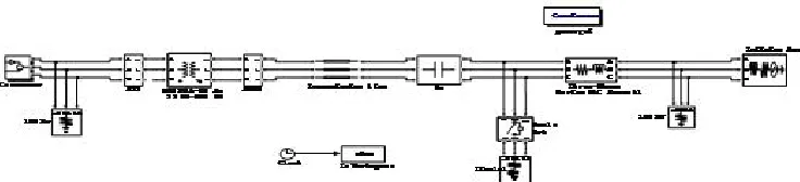
8. IEEE FIRST BENCH MARK MODEL
The system shown below is an IEEE first benchmark model used to study sub synchronous resonance and particularly stress calculation on a series compensated power system. It consists of a single generator (892.4 MVA, 500 KV, 50 Hz, 3000 rpm) connected a load via a series compensated transmission line. The sub synchronous mode introduced by the compensation capacitor after a disturbance has been applied and cleared excites the oscillatory torsional modes of the multi-mass shaft can be observed. The simulation model is shown in fig. 6.
Fig. 6. IEEE First Benchmark on Sub Synchronous Resonance System
D. Fixed series compensation:
The Torsional Oscillation phenomenon was applied for the case that torsional mode 1.for this case a fixed compensation with
X
fc= 0.236 p. u., to excite torsional mode 1 is simulated.Volume 2, Issue 9, September 2013
Page 121
Fixed series compensation with
X
fc= 0.236 p. u is divided into two parts. First, the GCSC,UPFC, and SSSC areoperated to provide the equivalent capacitive reactance of 0.130 p. u. and second, a series capacitor to provide the fixed capacitive reactance of 0.106 p. u. respectively.
9. STRESS ANALYSIS
For calculating Stresses for various shaft sections by knowing the deviation angle . By knowing set of equations of mechanical and electrical quantities for the calculation of deviation angle . This equation consists of input torque, output torque, damping torque and accelerating torque.
For N-mass system this equation can be written as
.
Where M is the diagonal matrix, consisting of all masses D and K are the tridiagonal symmetric matrix consisting of damping co-efficient and spring co-efficient.
T
m andT
e are the N-vectors of mechanical and electrical torques.T
e has only one non-zero element corresponding to generator rotor.
The above equation gives set of Torsional mode of the turbine-generator mechanical system in the state-space form. Where A is the state co-efficient matrix and u is the forcing torque vector
G
R
L
F
ij
i
j
The above equation is used to calculate stresses
F
ij for various shaft sections by knowing deviation angle1
,
ii
: twist angle ofi
th mass to the
i
1
th mass between Gen and HP masses (radians)G
: modulus of rigidity (N/m2)
L
: length of shaft (in meters)R
: radius of shaft (in meters)10. SIMULATION RESULTS
The Torsional Oscillations of the given system are the major SSR interaction when a steam turbine-generator is connected to a series compensated transmission line. Without FACTS controllers such as GCSC, UPFC, and SSSC the system become more unstable at different levels of series compensation.
The One line diagram for IEEE First Benchmark Model is shown in Fig.1 is modeled in MATLAB Simulink. Time domain simulations for three phase fault at infinite bus are observed. Initial fault duration for three phase fault is 0.1 sec. The simulation results for without GCSC, UPFC and SSSC and with GCSC, UPFC, and SSSC are compared.
0 1 2 3 4 5 6 7 8 9 10
x 104
-1.5 -1 -0.5 0 0.5 1 1.5 2 2.5
Time in second
P o w e r in p .u
Figure.7. Variation of power without GCSC, UPFC, SSSC
0 5 10 15
x 104
-1 -0.5 0 0.5 1 1.5 2 2.5
Time in second
P o w e r i n p .u
Figure.8. Variation of Power with GCSC
Te
Tm
K
D
M
mi ei
i i T T M X MD MK X 1 0 0
A
X
B
u
X
Volume 2, Issue 9, September 2013
Page 122
0 1 2 3 4 5 6 7 8 9 10
x 104 -0.5 0 0.5 1 1.5 2 2.5 3
Time in second
P o w e r i n p .u
Figure.9. Variation of Power with UPFC
0 5 10 15
x 104
-0.5 0 0.5 1 1.5 2 2.5 3
Time in second
P o w e r i n p .u
Figure.10. Variation of Power with SSSC
0 1 2 3 4 5 6 7 8 9 10
x 104 -0.2 0 0.2 0.4 0.6 0.8 1 1.2
Time in second
S p e e d in p .u
Figure
.
11. Variation of speed without GCSC, UPFC and SSSC0 5 10 15
x 104
-0.025 -0.02 -0.015 -0.01 -0.005 0 0.005 0.01 0.015 0.02
Time in second
S p e e d in p .u
Figure.12. Variation of Speed with GCSC
0 1 2 3 4 5 6 7 8 9 10
x 104
-0.025 -0.02 -0.015 -0.01 -0.005 0 0.005 0.01 0.015 0.02
Time in second
S p e e d in p .u
Figure.13. Variation of stress between Gen and LPB with UPFC
0 5 10 15
x 104 0.975 0.98 0.985 0.99 0.995 1 1.005 1.01 1.015 1.02 1.025
Time in second
S p e e d in p .u
Volume 2, Issue 9, September 2013
Page 123
0 1 2 3 4 5 6 7 8 9 10
x 104
-1 -0.8 -0.6 -0.4 -0.2 0 0.2 0.4 0.6 0.8 1x 10
10
Time in second
S
tr
e
s
s
in
N
/m
2
Figure.15. Variation of stress between Gen and LPB without GCSC, UPFC, and SSSC
0 5 10 15
x 104
-0.5 0 0.5 1 1.5 2 2.5
3x 10
7
Time in second
S
tr
e
s
s
in
p
.u
Figure.16. Variation of stress between Gen and LPB with GCSC
0 1 2 3 4 5 6 7 8 9 10
x 104
-1 -0.5 0 0.5 1 1.5 2 2.5
3x 10
7
Time in second
S
tr
e
s
s
i
n
N
/m
2
Figure.17. Variation of stress between Gen and LPB with UPFC
0 5 10 15
x 104
-1 -0.5 0 0.5 1 1.5 2 2.5 3x 10
7
Time in second
S
tr
e
s
s
i
n
p
.u
Figure.18. Variation of stress between Gen and LPB with SSSC
11. CONCLUSION
In this paper, Sub Synchronous Resonance effect is studied using IEEE First Benchmark Model, and we have presented the analysis and simulation of series compensated system with Flexible A.C Transmission System Controllers such as GCSC, UPFC and SSSC.The effect of two system without FACTS devices and with FACTS devices such as GCSC, UPFC and SSSC are compared. Time domain simulations using the nonlinear system model are also carried out to investigate the performance of the GCSC, UPFC, and SSSC under the condition of a three-phase fault at the infinite bus. The analyzed results shows that the proposed FACTS controllers can effectively stabilizes the common mode torsional oscillations.
REFERENCES
[1] Kundur P, “Power System Stability and Control,” New York, McGraw Hill, 1994.
[2] IEEE Sub synchronous Resonance Task Force, First Benchmark Model for Computer Simulation of Sub synchronous Resonance, IEEE Transactions. On Power Apparatus and systems. Vol. 96, No. 05, pp 1565-1572, 1977.
Volume 2, Issue 9, September 2013
Page 124
[4] W.Bo and Z. Yan, “Damping sybsynchronous oscillation using UPFC-A FACTS device”, Proceedings International Conference on Power Systemm Technologies. Vol 4 – Powercon2002, pp 2298-2301, October 13-17, 2002.
[5] K.R. Padiyar, Nagesh Prabhu, Analysis of subsynchronous resonance with three-level 12-pulse VSC based SSSC, IEEE TENCON-2003 (14-17 october) 76-80.
[6] N.G. Hingorani, L. Gyugyi, Understanding FACTS, IEEE Press, New York, 2000.
[7] C.D. Schauder, et al., Operation of the unified power flow controller (UPFC) under practical constraints, IEEE Trans. Power Deliv. 13 (2) (1998) 630–639.
[8] N. Kakimoto and A. Phongphanphanee, “Sunsynchronous resonance damping controlof thyristor-controlled series capacitor”, IEEE Transactions on Power Delivery, vol. 18, no. 3, pp 1051-1059, July 2003.
[9] Paul H. Black, “Machine Design”, Mc-Graw Hill Book Company, Inc, New York, 1955.
[10]N. C Pandya and C. S. Shah, “Elements of Machine Design”, Anand Press, Anand, Gujrat, India, 1978.
[11]D. N. Walkar C.E.J. Bowler, R. L. Jackson and D. A. Hodges, “Results of sub synchronous resonance test at Mohave,” Transactions on Power Apparatus & System, vol. PAS-94, no.5, pp 1878-1885. Sept/Oct 1975.
[12]D. D. Walker, E. J. Bowler, R. L. Jackson, D. A. Hodges, "Results of subsynchronous resonance test at Mohave", IEEE PES Winter Meeting, New York, USA, 1975.
[13]P. M. Anderson, B. L. Agrawal, J. E. Van Ness, "Subsynchronous Resonance in Power Systems", IEEE Press, New York, USA, 269 pages, 1990.
[14]SEN,K.K.: “ SSSC-“ Static Synchronous Series Compensator: Theory, Modeling and applications”, IEEE Trans.,1997 PD-13.