Volume 1, Issue 3, November 2012
Page 62
A
BSTRACTIn this paper performance of the induction motor under various load condition have been presented. The motor is controlled using a sensorless VFD control drive. The specification of the motor tested and controller drive is given in the section IV. Section I and II gives a brief summary of a VFD controller and induction motor. Later in section III the commissioning of the control drive has been presented. Various torque speed and torque current characteristics have been presented in section IV for various load condition. The tested motor is then used in an electromechanical drive for a launcher.
1.
I
NTRODUCTIONVARIABLE FREQUENCY DRIVE
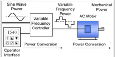
The variable frequency drive controller is a solid state power electronics conversion system consisting of three distinct sub-systems: a rectifier bridge converter, a direct current (DC) link, and an inverter. Voltage-source inverter (VSI) drives (see 'Generic topologies' sub-section below) are by far the most common type of drives. Most drives are AC-AC drives in that they convert AC line input to AC inverter output. However, in some applications such as common DC bus or solar applications, drives are configured as DC-AC drives. The most basic rectifier converter for the VSI drive is configured as a three-phase, six-pulse, full-wave diode bridge.
Figure 1 block diagram of the induction motor with VFD controller
In a VSI drive, the DC link consists of a capacitor which smooths out the converter's DC output ripple and provides a stiff input to the inverter. This filtered DC voltage is converted to quasi-sinusoidal AC voltage output using the inverter's active switching elements. VSI drives provide higher power factor and lower harmonic distortion than phase-controlled current-source inverter (CSI) and load-commutated inverter (LCI) drives. The drive controller can also be configured as a phase converter having singlephase converter input and three-phase inverter output.[7] Controllers have been improved to exploit quantum solid state power switching device improvements in terms of voltage and current ratings and switching frequency over the past six decades. Introduced in the 1983,[8] the insulated-gate bipolar transistor (IGBT) has in the past two decades come to dominate VFDs as an inverter switching device.[9][10][11] In variable-torque applications suited for Volts per Hertz (V/Hz) drive control, AC motor characteristics require that the voltage magnitude of the inverter's output to the motor be adjusted to match the required load torque in a linear V/Hz relationship. Some V/Hz control drives can also operate in quadratic V/Hz mode or can even be programmed to suit special multi-point V/Hz paths.[12][13] The two other drive control platforms, vector control and direct torque control
Commissioning of A VFD Controller For The
Performance Analysis of A 2 Pole Induction
Motor
Ram Singh1, Navdeep Choudhary2, Alok Mishra3, Ketandeep Jamwal4, Mukund Madhav5
1
A.P, Electrical Engineering, BHSBIET – Lehragaga 1
HOD & A.P of. Electronics & Communication Engineering, BHBIET –Lehragaga 2
Design Engineer in TATA Power Corp. Mumbai
B-tech 4th year, Electronics & Communication Engineering, BHBIET –Lehragaga4
Volume 1, Issue 3, November 2012
Page 63
Additional operator control functions might include reversing, and switching between manual speed adjustment and automatic control from an external process control signal. The operator interface often includes an alphanumeric display and/or indication lights and meters to provide information about the operation.
2.
INDUCTION
MOTOR
Three-phase induction motors are the most common and frequently encountered machines in industry
simple design, rugged, low-price, easy maintenance
wide range of power ratings: fractional horsepower to 10 MW
run essentially as constant speed from no-load to full load
Its speed depends on the frequency of the power source
not easy to have variable speed control
requires a variable-frequency power-electronic drive for optimal speed control
Figure 2 a view of induction motor
An induction motor has two main parts: 1. a stationary stator
consisting of a steel frame that supports a hollow, cylindrical core
core, constructed from stacked laminations, having a number of evenly spaced slots, providing the space for the stator winding
2. a revolving rotor
composed of punched laminations, stacked to create a series of rotor slots, providing space for the rotor winding
one of two types of rotor windings
conventional 3-phase windings made of insulated wire (wound-rotor) » similar to the winding on the stator
aluminum bus bars shorted together at the ends by two aluminum rings, forming a squirrel-cage shaped circuit (squirrel-cage).
3.
STARTER
DRIVE
/COMMISIONING
SOFTWARE
Volume 1, Issue 3, November 2012
Page 64
Figure 4 view of Siemens companies vfd drive
4.
PERFORMANCE
ANALYSIS
OF
THE
INDUCTION
MOTOR
TECHNICAL SPECIFICATIONS OF MOTOR TESTED
Table.1 technical specification of the motor drive used
Sl no Factors Ratings
01 Power 3.7 kw
02 Full load current 7.1 a
03 Speed 2900 rpm
04 Voltage 415 v, 3 phase
05 Power factor 0.82
06 Serial no. Nosdf/1103 2308978
TECHNICAL SPECIFICATION OF DRIVE USED
Table 2 technical specification of the control drive used
SL NO. FACTORS DETAILS
01 COMPANY SIEMENS
02 POWER 4 KW
03 I/P VOLTAGE 380-480 V 04 I/P CURRENT 13.4 A 05 FREQUENCY 50 HZ
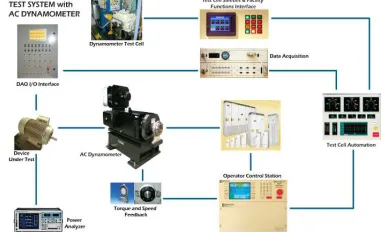
06 MODEL NO. 6SL 3224 - OBE24 - OUAO TEST SET UP
The following figure shows the test set for the evaluation of the performance of the induction motor in the motor testing cell. It include the mounting bench over which both the motor and dynamometer are horizontally coupled. The three phase star connected connections of the motor input are connected to the three phase output connections of the drive which generates the PWM signals.the three phase input connections to the drive are made from the three phase 440 v main supply board. The earthing facility is provided for both motor and drive. Initially the dynamometer is not loaded but then also the motor rotate with a torque at no laod due to the coupling with the dynamometer. The cooling pipes are connected to the dynamometers for cooling purpose during the test.
Volume 1, Issue 3, November 2012
Page 65
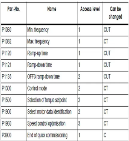
Similarly set the other factors of the motors in the drive using the following table:
Table 3 parameters used for the quick commissioning of the drive
Table 4 commissioning parameters of the vfd drive used
Volume 1, Issue 3, November 2012
Page 66
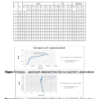
Sr Motor Drive Dynomometer No. Time Speed Torque I/P Vtg. Current Freq. Power Temp. I/P VoltageCurrent Freq. dc Voltage Speed Power Torque
(N-m) (Volts) (Amps) (Hz) (kW) (Deg. C) (Volts) (Amps) (Hz) (Volts) (kW) (N-m) 1 14:00 299 0 46 2.8 5 0 24 423 0.4 50 587 298 0.01 0.34 2 14:05 599 1.1 86 2.5 10 0.07 24 424 1.1 50 586 597 0.01 0.34 3 14:10 899 1.3 127 2.41 15 0.12 25 424 2.1 50 583 897 0.02 0.34 4 14:15 1199 1.42 168 2.43 20 0.18 25 424 3.3 50 580 1196 0.04 0.37 5 14:20 1499 1.87 209 2.53 25 0.29 27 424 6 50 582 1494 0.01 0.13 6 14:25 1799 1.43 250 2.23 30 0.27 30 424 7.6 50 586 1797 0.05 0.2 7 14:30 2099 1.51 291 2.57 35 0.33 30 423 9.1 50 581 2096 0.03 0.07 8 14:35 2399 1.62 332 2.61 40 0.4 31 423 10.8 50 580 2396 0.02 0.05 9 14:40 2699 1.78 373 2.64 45 0.5 31 424 11.1 50 577 2695 0.02 0.04 10 14:45 2999 1.78 400 4.67 50 0.56 32 424 12.1 50 577 2996 0.02 0.08
Sr Motor Drive Dynomometer No. Time Speed Torque I/P Vtg. Current Freq. Power Temp. I/P VoltageCurrent Freq. dc Voltage Speed Power Torque
(N-m) (Volts) (Amps) (Hz) (kW) (Deg. C) (Volts) (Amps) (Hz) (Volts) (kW) (N-m) 1 15:30 299 0 47 2.7 5 0 48 423 0.4 50 591 284 0.05 1.44 2 15:35 599 4.46 87 2.98 10 0.28 49 424 1.1 50 585 569 0.1 1.74 3 15:40 899 5.87 128 3.54 15 0.55 50 424 2.1 50 582 858 0.17 1.95 4 15:45 1199 7.11 169 4.05 20 0.89 51 424 3.3 50 573 1148 0.26 2.12 5 15:50 1499 8.16 210 4.52 25 1.27 52 424 6 50 570 1440 0.35 2.34 6 15:55 1799 9.07 251 4.98 30 1.7 53 424 7.6 50 556 1732 0.54 3.04 7 16:00 2099 9.86 292 5.29 35 2.15 53 423 9.1 50 564 2027 0.66 3.1 8 16:05 2399 10.54 333 5.59 40 2.63 53 423 10.8 50 564 2323 0.87 3.55 9 16:10 2699 11.14 374 5.86 45 3.13 51 424 11.1 50 563 2619 1.13 4.6 10 16:15 2999 11.7 414 6.1 50 3.65 49 424 12.1 50 562 2916 1.42 4.76
Chart .1 readable parameters of the vfd drive used MOTOR PERFORMANCE AT NO LOAD
Table 5 observation table for no-load test of the induction motor
Figure 5 torques – speed plot obtained from the no load test’s observations
Figure 6 torque – current plot obtained from the no load test’s observations MOTOR PERFORMANCE UNDER FULL LOAD
Volume 1, Issue 3, November 2012
Page 67
MOTOR PERFORMACE UNDER 110% OVER LOAD
Table 7 observation table for the over-load test of the tested induction motor
Sr Motor Drive Dynomometer No. Time Speed Torque I/P Vtg. Current Freq. Power Temp. I/P VoltageCurrent Freq. dc Voltage Speed Power Torque
(N-m) (Volts) (Amps) (Hz) (kW) (Deg. C) (Volts) (Amps) (Hz) (Volts) (kW) (N-m) 1 16:20 299 0 47 2.76 5 0 34 423 0.4 50 578 285 0.05 1.21 2 16:22 599 4.8 86 3.09 10 0.39 37 424 1.1 50 573 568 0.09 1.5 3 16:25 899 6.9 127 3.96 15 0.59 40 424 2.1 50 560 857 0.16 1.76 4 16:27 1199 7.58 168 4.26 20 0.95 41 424 3.3 50 553 1146 0.24 1.9 5 16:30 1499 8.71 209 4.76 25 1.36 41 424 6 50 551 1438 0.36 2.45 6 16:35 1799 9.69 250 5.23 30 1.82 42 424 7.6 50 551 1732 0.54 2.98 7 16:40 2099 10.53 291 5.6 35 2.3 43 423 9.1 50 550 2027 0.8 3.75 8 16:45 2399 11.25 332 5.92 40 2.81 44 423 10.8 50 548 2322 1.11 4.4 9 16:50 2699 11.87 373 6.2 45 3.34 45 424 11.1 50 548 2620 1.38 4.96 10 16:55 2999 12.6 412 6.53 50 3.93 46 424 12.1 50 547 2914 1.67 5.44
Figure 9 toque v/s speed plot of the tested induction of the tested induction motor
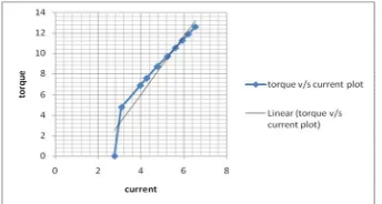
Figure 10 toque v/s current plot of the tested induction motor under over-load test
5.
CONCLUSSIONS
The following conclusions were made after undergoing the above tests for the induction motor of siemence company :
The characteristic performance of the induction motor under no-load test was satisfactory as compared with the ideal characteristics.
The characteristic performance of the induction motor under full-load test was satisfactory as compared with the ideal characteristics.
The characteristic performance of the induction motor under over-load test was satisfactory as compared with the ideal characteristics.
The characteristic performance of the induction motor under endurance test was satisfactory as compared with the ideal characteristics.
The motor is suitable to be used in the required area of the launcher.
Volume 1, Issue 3, November 2012
Page 68
REFRENCES
[1] A. E. Fitzgerald, et al., "Electric Machinery," 5th Ed., McGraw-Hill, 1990.
[2] IEEE Standard 112-1991, "IEEE Standard Test Procedure for Polyphase Induction Motors and Generators," Institute of Electrical and Electronics Engineers, Inc.
[3] G. R. Slemon,"Modelling Induction Machines for Electric Drives," IEEE Trans. on Industry Applications, Vol. 25, No. 6, pp. 1126-1131, Nov. 1989.
[4] D. W. Novotney, et al.(Editor), "Introduction to Field Orientation and High Performance AC Drives," IEEE IAS Tutorial Course, 1986.
[5] A. M. Trzynadlowski, “The Field Orientation Principle in Control of Induction Motors,” Kluwer Academic Publishers 1994.
[6] J. Holtz, "Pulse Width Modulation for Electronic Power Conversion," Proceedings of IEEE, Vol.82, No.8, p.1194-1214, Aug. 1994. 10