DOI: 10.9781/ijimai.2015.352
A New Approach for Hiding Image Based on the
Signature of Coefficients
Tawfiq A. Al-asadi, Israa Hadi Ali, Abdul kadhem Abdul kareem Abdul kadhem
Information Technology College, University of Babylon, Iraq
Abstract — This paper presents a new approach for hiding the secret image inside another image file, depending on the signature of coefficients. The proposed system consists of two general stages. The first one is the hiding stage which consist of the following steps (Read the cover image and message image, Block collections using the chain code and similarity measure, Apply DCT Transform, Signature of coefficients, Hiding algorithm , Save information of block in boundary, Reconstruct block to stego image and checking process). The second stage is extraction stage which consist of the following steps ( read the stego image, Extract information of block from boundary, Block collection, Apply DCT transform, Extract bits of message and save it to buffer, Extracting message).
Keywords —Information hiding, Steganography, Chain code, DCT, Signature of coefficients.
I.
Introduction
C
ommunication in our world are today based on the use of wide world website (the Internet) where anyone can send anything to any place on earth, every day trillions of messages and information are sent and received in seconds. Encrypted data are always suspicious, and considered illegal in some places in the world. Information hiding has become very important as it works on converting information to be hidden and hard to discover [1].Information hiding is a general term that contains many other topics (steganography, watermarking, copyrighting). This paper concentrate on Steganography, which is a field of science that works on hidden communication that hides a message in a way that no one knows about it only the sender and the intended recipient, where there is no attention for the hidden information and cannot be attacked easily . It is different from cryptography where information is unreadable but not invisible [2].
Steganography technique hides important information that should be secret in normal media (audio, digital image, video, and so on). Any attempt to extract hidden information from stego is called Steganalysis. The Steganographic algorithm is considered to be broken if a steganalytic algorithm detect a given media to be a carrier for a secret message [3].
The secret message can be hidden inside the cover image in some locations according to a particular algorithm. This paper will introduce a new technique for information hiding based on chain code and DCT. The chain code is used to determine some locations of cover image for hiding a message by developing the traditional freeman chain code with 8-connectivity to quad chain code , the quad chain code is found depending on one of the measures which is the similarity between two adjacent vectors (quad pixels). While the DCT is used to determine the locations of a block for hiding operation and use it as a signature to support the hide operation.
II.
Related works
Zuheir in [4] proposed a steganography method to hide text in the cover image by using traditional chain code, first generate a chain code and store it in the cover image then store the embedded text in the cover image according to the generated chain code. The system uses the first pixel of the cover image to specify the location of the starting point to begin with it. The second pixel contains the length of the secret message where each character needs 8 bits for representation. The system divided the image into two sections the first section contains the chain code which represent the map of the secret message and the second section include the secret message which the sender pass.
Our proposed system implements a new hiding technique by using similarity measure (cosine similarity) to generate chain code, each value of chain code represent the movement between two vectors (two neighbor quad pixels) in the cover image. The chain code was used to collect blocks, each block with size 8*8 for hiding operation.
Ajit and et al [5] proposed a novel image steganography technique by embedding a bit that is randomized. First operation is obtaining the DCT of the cover image, and then constructing the stego image by hiding the secret message that was given in least significant bit of the cover image in random locations depending on the threshold. The locations of the randomized pixel are determined by DCT coefficients for hiding.
Authors in [6] proposed an LSB and DCT steganographic technique for data hiding that applies spatial domain with frequency domain of steganography methods and asymmetric key cryptography. It’s done by utilizing a significant bit of low frequency DCT coefficients of the cover image blocks hiding encrypted message bits. 2D-DCT converts the image block from the spatial domain to the frequency domain, and then bits of data are embedded by changing LSB of DCT coefficients.
Our proposed system implements the information hiding technique in the spatial domain. The hiding operation is not sequential but randomly based on the chain code and the nature of data that are dealing with it. The chain code technique is used to equipment pixels or quads (each quad = 4 pixels) of the cover image that are more similar with each other as blocks. The system utilizes the DCT to find the coefficients values that are zero or near to zero (between 1,-1) that were used to determine the signature of coefficients. That means, if the block elements are more similar with each other, is that will give high zero values after applying the 2D-DCT. According to the simulated results (MSE and PSNR), it is so difficult differing the genuine image from the stego image of our proposed algorithm, as they seem to be identical.
III.
Background
A. Steganography.
in another message or carrier called “cover media”. The use of cover media facilitates, secure information transfer over commonly available public domain open channels that are insecure networks like the internet and wireless mobile networks. Although the evolution of these broadband networks has permitted cost-effective and high speed multimedia information transfer, but it has posed increasing threats to the information security due to greater possibilities of unauthorized information access. The issue of securing information becomesmore challenging in internet environment because it is open across the globe and being extensively used for information access and dissemination [7].
Steganography is a field of science for hiding information by embedding a message in other information. It is derived from the
Greek words “STEGOS” which means ʻ cover ʼ and “GRAFIA” which means ʻ writing ʼ to be ʻ covered writing ʼ. Steganography is done by
replacing bits of unused data in regular computer files (like sounds, graphics, HTML, texts, or image) with bits of invisible information. The information that is hidden can be any kind of text (plain text, cipher text), sound or images [8].
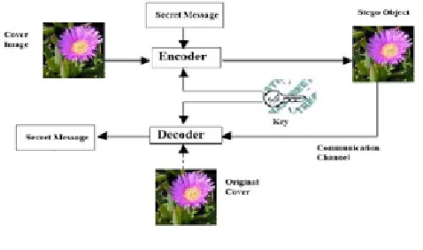
Information hiding in digital steganography is achieved by hiding the secret data with other seemingly innocuous cover object or carrier where message data is embedded under the cover using a key to generate the stego object. The object that is covered refers to the used object as the carrier to hide the messages and the stego object is one which contains the secret message [9]. Fig (1) explains steganography principle.
Fig. 1. Steganography principles.
General model to hide data in another data can be described as follows [10]:
1. Cover file (carrier): is used for hiding information and the size of the file is carefully selected to be enough for embedding the information that have to be secret.
2. Message file (secret file): contains secret information that has to be hidden and must be kept save during transformation. 3. Steganography algorithm: refers to the deterministic sequence
for using a cover file to hide a secret message.
4. Stego file: is what follows embedding that embeds the secret message in the cover file using steganography algorithm. 5. Retrieve algorithm: is used for extracting the message that is
secret from the stego file, the retrieved algorithm runs in a reversing way than the embedding algorithm.
6. The cover file and the message file may take many different files like audio files, text, image, and video files (e.g. .doc, .html, .wma, .jpeg, .tiff, .bmp, .gif, .wav, .mp3, and mp4, etc.).
B. Chain code.
Freeman Chain Code (FCC) was the first technique to represent an image that uses chain code; it was introduced by Freeman in 1961. Straight-line segments that are connected in sequence with particular length and direction are represented as a boundary by using this chain code. This representation is based on 4- or 8-connectivity of the segments. A numbering scheme is used to code the direction of each segment. 4-connected Freeman Chain Code is shown in fig (2-a) while fig (2-b) shows 8-connected Freeman Chain Code of 8-directional (FCCE) [11].
Fig. 2. Neighbor directions of freeman chain code.
In the Freeman Chain Code 8-connected (FCCE), 8 directions from one pixel to a neighbor pixel are possible, every code is considered as an angular direction, multiplied by 450 moving from one contour pixel to the next. Direction 0 means move “to the right of”, 2 means “immediately above”, and 1 is at 45 degrees, bisecting 0 and 2, and so on. Fig (3) shows the examples using the 8-connected path and 4-connected path of Freeman Chain Code.
Fig. 3. Example of chain code
A. 4-connectivity chain code = 00303032323221112110 B. 8-connectivity chain code = 0770655432231
C. Discreet Cosine Transform (DCT)
The input data points are represented by DCT as the sum of cosine functions that are oscillating at different dimension and frequencies. There are generally two kinds of DCT: one dimensional (1-D) DCT and two dimensional (2-D) DCT. 2-D DCT is considered for this study work. For an input sequence, the 2-D DCT can be described as follows: [13].
As effectively as possible, the DCT is protected against blocking artifact with no blocks that are interconnected since all DCT basis functions have a zero gradient at the edges of their blocks. In another word, only the DC level affects the blocking artifact and then can be targeted. In DCT operation ringing is a main problem. To make the image shaper DCT depends on the high frequency components, when edges happen in an image.
Though the components with the high frequency that continued firmly across the whole block are effective at improving the edge quality, they ‘ring’ in the flat areas of the block [13].
IV.
The proposed system
The proposed method consists of two general stages (the message hiding stage, the extracting message stage). Ech one consists of many steps.
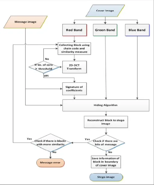
A. The message hiding stage
In this stage there are many steps as illustrated in Fig (4) of hiding a gray scale image (8 bit per pixel) in the cover image (color image – 24 bit per pixel) depending on the signature of coefficients , it consists of the following steps :
1) Read the cover image and message image
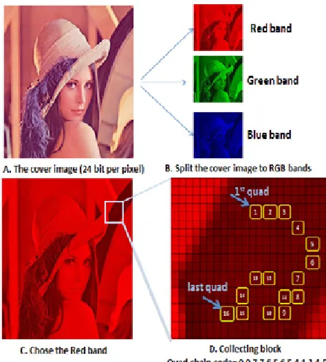
Images are simply 2D arrays of colors where each color is represented using one of the color formats (8, 16, 24, or 32 bits).This step will choose an image with size M*N to be a cover which is a color BMP image (24 bit per pixel). This image will be converted to three bands (Red, green, blue) RGB each band is a 2D array with size M*N too. While the secret message is a BMP gray scale image (8 bit per pixel) that we need to hide inside the cover image and convert it to a stream of bits.
2) Collecting block based on chain code and similarity
measure
In this step, we will collect a block with size 8*8 which pixels more similar with each other. The proposed system will we use the chain code to choose the similar pixels by developing the freeman chain code to quad chain code using quadruple pixel (each quad as a vector of 4 pixels), this step is find the chain code for the red band of the cover image depending on one of the similarity measures that were used to find the two adjacent vectors (four pixels or quad) that are almost similar.
The similarity measures can be applied in the system to find vectors (quad of pixels) that are more alike (cosine similarity) as illustrated in the following equation [14]:
For example, if A and B as the vector, when A vector =(1,3,7,4) and B vector =(5,3,1,6). Where:
||A|| = (1*1 + 3*3 + 7*7 + 4*4 ) =75. ||B|| = (5*5 + 3*3 + 1*1 + 6*6 ) =71.
A∙B = (1*5 + 3*3 + 7*1 + 4*6 ) = 45.
Cosine (A,B) = 0.61669.
As long as similarity measure return values in the range [0,1],when the similarity value is closer to 1 that mean blocks are more alike and vice versa.
Quad chain code that was found by scanning the pixels of the red band of cover image checks if there are (16) quads similar with each other to collect a block with size 8*8 (16 quad pixels equal 64 pixel).
Fig (5) explains how to collect a block from the cover image depending on chain code and similarity measure.
Fig. 5. Collecting block with size 8*8 pixels
3) Apply DCT Transform for a block
This step will apply the 2D-DCT transform for the block that was equipmented from the above step to convert values of pixels from the spatial domain to frequency domain. As shown in fig (6) which explain this step.
The next operation of this step is computing the number of zero or zeros values (between 1,-1) in coefficients of DCT array and compare it with threshold, if the number of zero is larger than threshold then go to the next step, else must go to the above step and collect another block for hiding operation.
4)
Signature of coefficients
This step is checking the number of bits (message) that can be embedded inside the block that was collected from above. The first operation is extracting the mask matrix with size 8*8 by determining which locations of DCT coefficients have a zero value or values between 1). That means if each element of DCT coefficients is between (1,-1), then the corresponding value in mask matrix will be ((1,-1), otherwise the remaining values will be (0). Except the values of the first row and the first column of mask matrix that will be the (0) value.
The next operation is computing the number of (1) values in the mask matrix to determine three parameters (low, mid, high). The values of these parameters are computed as follow:
Low =0.
High= number of (1) values in the mask matrix. Mid= (Low + High) / 2.
The mid value is used to determine how many hiding operations are there for the block. The bits of the message must be hidden in locations of corresponding spatial domain block that mask matrix is (1) by using least significant bit (LSB) algorithm .the strategy that is going to be applied is bottom- up. For each hide operation to a number of the block positions, we will find the 2D-DCT to the block after hiding. Then we create the signature coefficients matrix according to the values of the DCT block (which means each element of DCT coefficients between (1,-1) the corresponding value in signature coefficients matrix will be (1), otherwise the remaining values will be (0). Except the values of the first row and the first column, the signature coefficients matrix will be (0) value).
The next operation is comparing the signature coefficients matrix with the mask matrix that has been extracted in the beginning to update the values of (low, mid, high). This operation will be benefited from the idea of binary search algorithm (divide and conquer) to update the (low, mid, high) if the signature coefficients matrix are equal to the mask matrix, that means increase bits of the message to hide in the block, otherwise must decrease bits of message that are hidden in the block. The new values of (low, mid, high) are explained in the following paragraph:
If signature coefficients matrix equal to the mask matrix then Low = Mid.
High=High.
Mid = (Low + High) /2.
If signature coefficients matrix not equal to the mask matrix then Low= Low
High= Mid
Mid= (Low+ High) /2.
In the next level, We will process a new hide by embedding bits of message in the block based on the value of (mid) which were extracted from the first level, also we apply 2D-DCT for the block after hiding, and extract the new signature of coefficients matrix from the DCT block, comparing between the signature of coefficients matrix and the mask matrix and the values (low, mid, high) that were updated based on the comparison result.
The successive levels will continue until all values (low, mid, high) are equal with each other. The output of this step is (mid value) that represent the number of bits (message) that can be embedded in the block without changing the signature of coefficients matrix compared with the mask matrix. The aim of this step is to ensure the integrity of the message without any loss in the extraction message from the stego-image stage.
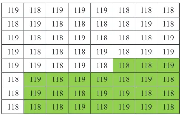
To explain this step, consider the following message “011010000 1100101011011000110110001101111” that was needed to hide in the following cover block with size 8*8 as illustrated in figure (7).
119 118 119 119 119 118 118 118 118 119 118 118 118 118 119 118 119 118 118 119 118 118 118 119 119 118 118 118 119 118 119 119 119 119 118 119 118 118 118 119 118 118 118 118 118 118 118 118 118 119 118 118 119 119 118 118 118 118 118 119 118 119 119 118 Fig. 7. An example of the cover block.
The first operation is finding the mask matrix that was extracted depending on the DCT block (applying the 2-D DCT transform for the cover block and find the mask matrix from DCT transform block), and compute the parameters (low, mid and high) according to the mask matrix, figure (8) shows this operation.
A. DCT transform block B. mask matrix Fig. 8. Find the mask matrix.
The low value is (0) in the beginning, the high value is (48) that represent number of (1) values in the mask matrix while the mid value is (24).
Depending on the mid value, the first level is hide (24) bit of message “011010000110010101101100” in the cover block from down to up by using least significant bit (LSB), the next operation is applying 2D-DCT transform for a block after hiding, the next operation is finding the signature of coefficients matrix after the first hiding operation. Fig (9) explains the first level for the signature of coefficients.
A. The Cover block after level (1)
B. Apply DCT transform for the block C. signature matrix Fig. 9. An example of the first level for the signature of coefficients.
The last operation of the first level is finding the comparison between the mask matrix and the signature matrix to extract the new values of (low, mid, high). We note that the mask matrix is equal to the signature matrix that means increase the bits of message hidden in the cover block. The new low value is (24), the high value is (48) without any change, while the mid value is ((24 + 48) / 2= 36).
The second level is hide (36) bit of message “01101000011001010 1101100011011000110” in the cover block from down to up by using least significant bit (LSB), the next operation is applying 2D-DCT transform for a block after the second hiding, the next operation is finding the signature of coefficients matrix for the cover block. We notice that the mask matrix is equal to the signature matrix, which means, decreasing the bits of message hidden in the next level, Fig (10) explains the second level for the signature of coefficients.
119 118 119 119 119 118 118 118 118 119 118 118 118 118 119 118 119 118 118 119 118 118 118 118 119 119 119 118 118 118 119 119 119 118 119 119 118 118 118 119 118 119 118 119 119 118 119 118 118 119 118 118 119 119 118 118 118 118 118 119 118 119 119 118
A. Cover block after level (2)
B. Apply DCT transform for the block C. signature matrix Fig. 10. An example of the second level for the signature of coefficients.
The new low value is (24) without any change, the high value is (36), while the mid value is ((24 + 36) / 2= 30).
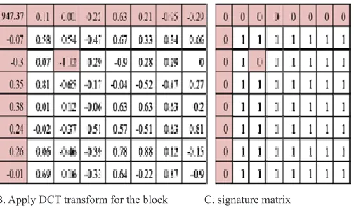
The third level is hiding (30) bits of message “0110100001100101 01101100011011” in the cover block from down to up by using least significant bit (LSB), the next operation is applying 2D-DCT transform for a block after the third hiding, next operation is finding the signature of coefficients matrix for the cover block. We notice that the mask matrix is not equal to the signature matrix, that means, decrease the bits of message hidden in the next level. Fig (11) explains the third level for the signature of coefficients.
119 118 119 119 119 118 118 118 118 119 118 118 118 118 119 118 119 118 118 119 118 118 118 119 119 118 118 118 119 118 119 119 119 118 119 119 118 118 118 119 118 119 118 119 199 118 119 118 118 119 118 118 119 119 118 118 118 118 118 119 118 119 119 118
A. The Cover block after level (3)
B. Apply DCT transform for the block C. signature mask Fig. 11. An example of the third level for the signature of coefficients.
The new low value is (24) without any change, the high value is (30) , while the mid value is ((24 + 30) / 2= 27).
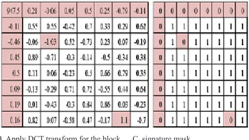
The fourth level is hiding (27) bits of message “011010000110010101101100011” in the cover block from down to up by using least significant bit (LSB), the next operation is applying 2D-DCT transform for a block after the fourth hiding, next operation is finding the signature of coefficients matrix for the cover block. We notice that the mask matrix is not equal to the signature matrix, that means, decrease the bits of the message hidden in the next level. Fig (12) explains the fourth level for the signature of coefficients.
119 118 119 119 119 118 118 118 118 119 118 118 118 118 119 118 119 118 118 119 118 118 118 119 119 118 118 118 119 118 119 119 119 119 119 119 118 118 118 119 118 119 118 119 119 118 119 118 118 119 118 118 119 119 118 118 118 118 118 119 118 119 119 118
B. Apply DCT transform for the block C. signature mask
Fig . 12. An example of the fourth level for the signature of coefficients.
The new low value is (24) without any change, the high value is (27), while the mid value is ((24 + 27) / 2= 25).
The fifth level is hiding (25) bits of message “01101000011001010110110001” in the cover block from down to up by using least significant bit (LSB), the next operation is applying 2D-DCT transform for a block after the fifth hiding, next operation is finding the signature of coefficients matrix for the cover block. We notice that the mask matrix is equal to the signature matrix, which means, increase the bits of message hidden in the next level. Fig (13) explains the fourth level for the signature of coefficients.
119 118 119 119 119 118 118 118 118 119 118 118 118 118 119 118 119 118 118 119 118 118 118 119 119 118 118 118 119 118 119 119 119 119 118 119 118 118 118 119 118 119 118 119 119 118 119 118 118 119 118 118 119 119 118 118 118 118 118 119 118 119 119 118
A. The Cover block after level (5)
B. Apply DCT transform for the block C. signature mask Fig. 13. An example of the fifth level for the signature of coefficients.
The new low value is (25), the high value is (27) without change, while the mid value is ((25 + 27) / 2= 26).
The sixth level is hiding (25) bits of message “0110100001100101011011000” in the cover block from down to up by using least significant bit (LSB), the next operation is applying 2D-DCT transform for a block after sixth hiding, next operation is
finding the signature of coefficients matrix for the cover block. . Also fig (14) explains the sixth level for the signature of coefficients.
119 118 119 119 119 118 118 118 118 119 118 118 118 118 119 118 119 118 118 119 118 118 118 119 119 118 118 118 119 118 119 119 119 119 118 119 118 118 118 119 118 119 118 119 119 118 119 118 118 119 118 118 119 119 118 118 118 118 118 119 118 119 119 118
A. The Cover block after level (6)
B. Apply DCT transform for the block C. signature mask Fig. 14. An example the sixth level for the signature of coefficients
The new low value is (26), the high value is (27) without change, while the mid value is ((26 + 27) / 2= 26).
We notice the mid value is equal to the low value .the algorithm will be finished in this level. The number of bits of the message that can be embedded in the cover block are (26) bits.
5) Hiding algorithm
From the above steps, the system determines the number of bits that can be embedded in a block of the red band of cover image, and collecting the two corresponding blocks of the green and the blue bands depending on the quad chain code which was used to collect a block of red band. This step will hide stream of bits of the message in the least significant bit of pixels of the three blocks (the first block that was extracted in step 2 from the red band, the second block of green band and the third block of blue band that were extracted based on the quad chain code of the red band) from bottom to up (that means the initial hiding of each block will be in location (7,7) and we continue until we reach the location (1,1)).
6) Reconstruct block of stego image
This step will reconstruct the block from the above step to the stego image by assigning new values after hiding bits of a message image.
7) Checking step
There are two checking levels:
• The first one: check if there are bits of the message still not hidden in the stego image, if yes there will be another checking, otherwise must go to the next step (save information of the red block in the boundary of the stego image.
image that pixels are more similarity with each other. If yes then go to step (2). Otherwise must end the algorithm and upload another cover image because the current cover image cannot embed all bits of the secret image (message).
8) Save information of blocks in boundary
After the hiding operation for each block, the system will save the stream of chain code for the block of red band, start point of each block (red band) and number of hidden bits for blocks of red band in the first two boundaries of the red band of the stego image. The number of blocks that contain hidden bits will be saved in the 4 corner locations of stego image (embedded two bits for each corner location by using LSB algorithm, these locations are [0,0],[0,199],[199,199],[199,0]) . The stream of chain code(with size 15 for each block) will be embedded in the first boundary of the stego image except the corners, we note the values of chain code between (0-7) need 3 bits to be represented, then we need to embed 3 bits for each pixel in the first boundary of the stego image. After this step, the message hiding process is completed and the stego image is ready to be sent to the destination.
B. The extract message stage
In this stage there are several steps to extract a secret message from the stego image as follow:
1. Read the stego image and divide it into RGB (red band, green band, blue band).
2. Extract information of blocks that gets the hiding operation from the boundary of the red band.
3. Collect blocks with size (8*8) depending on the information hidden in the boundary of the red band, and find the two corresponding blocks of green and blue bands based on the same information that is used to collect the block of the red band.
4. Apply 2D DCT transform for each block and extract the signature of coefficients to determine locations of the block that gets hiding operation in it.
5. Extract bits of the message from blocks and save these bits in a buffer.
6. Convert bits in the buffer to the message image.
V.
Experimental Results
Experiments of proposed method carried out to prove the efficiency. The proposed method has been simulated using the visual basic 6.0 program on Windows 7 platform on Intel core i5 2.5 GHz with 4 GB of main memory. The quality of the stego image is measured through the mean square error (MSE) that returns cumulative squared error between the cover image and the stego image , and the Peak Signal to Noise Ratio (PSNR) that returns the ratio of the maximum signal to noise between two images(cover, stego), in decibels. The best values of error measures are when the MSE is low and the PSNR is large. The mathematical equation for this error measures are:
(3)
(4)
Where N, M are the dimensions of the cover image and stego image. The proposed system was hiding gray image in color image. the hiding operation is done by embedding the pixels of message in a color image
depending on the red band that it used to determine regions of cover image which will be hiding operation (each pixel of the message image (one byte) will be hidden in (three byte) of cover image, hide 2 bits in the red band, and hide 3 bits in the green band, and hide 3 bits in the blue band for each pixel in the cover pixels). There are two cases.
Case (1):
The cover image is a bitmap color image (24 bit for each pixel) with size (486*486), while the message is a bitmap gray scale image with size (50*50) which was used to test the proposed system as illustrated in fig (15). The similarity ratio between quads is 95%.
The cover image
The message
The stego image
Fig. 15. The cover image, the message, the stego image for case (1)
We note the size of message image are (2500) pixels, then converting these pixels to the binary representation for a given stream of bits with size (20000) bits. Figure (16) explains simulation for hiding operation as follows.
1. Read the cover image.
2. Apply quad chain code by scanning the cover image to find locations of the pixels (quads) that are more similar with each other (as illustrate in green color).
3. Determine the start point for each block of the cover image(as illustrated in red color, the bold red color represent the start point of blocks that got hiding operation, while the remaining red color represent the start point of blocks that did not get hiding operation .
Fig. 16. Simulation of hiding operation for case (1).
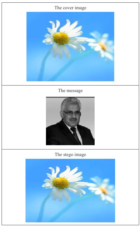
Case (2):
The cover image is a bitmap color image (24 bit for each pixel) with size (450*450), while the message is a bitmap gray scale image with size (51*51) which was used to test the proposed system as illustrated in figure (17). The similarity ratio between quads is 96%.
The cover image
The message
The stego image
Fig.17.The cover image, the message, the stego image for case (17).
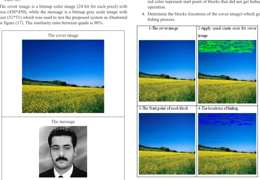
We note the size of message image are (2601) pixels, then converting these pixels to the binary representation for a given stream of bits with a size (20808) bit. Figure (18) explains simulation for hiding operation as follows.
1. Read the cover image.
2. Apply quad chain code by scanning the cover image to find locations of pixels (quads) that are more similar with each other (as illustrated in green color).
3. Determine the start point for each block of the cover image(as illustrate in red color, the bold red color represent the start point of blocks that got hiding operation, while the remaining red color represent start point of blocks that did not get hiding operation .
4. Determine the blocks (locations of the cover image) which got hiding process.
After applying the proposed system on two cases, we have access the following information as illustrated in table (1):
TABLE 1
ILLUSTRATES THE ANALySIS OF ALL CASES THAT ARE USED
Cover images Case(1) Case(2)
Size of cover image 486*486 450*450 Number of symbol (message) 2500 pixels 2601 pixels
Number of all blocks 458 306
Number of blocks which got in it
operation hiding 250 225
Input Similarity Ratio 95% 96%
MSE with Boundary 0.6520 10.34
PSNR with Boundary 49.9881 37.9833 MSE without boundary 0.2542 0.4829 PSNR without boundary 54.0783 51.2916
Time for hiding 11 sec. 12 sec. Time for extracting 3 sec. 3 sec.
VI.
Conclusions
The proposed method is experimented and efficiency of the approach is demonstrated. The randomization that we apply makes this scheme stronger and secured. The randomization comes from three directions as follow:
1. The first one is applying chain code that select quad pixels that are not sequential but random (may take the zigzag shape). 2. The second one is applying the 2D-DCT transform to find what
location gives zeros values (between 1,-1) which represent the signature of coefficients.
3. The third one is applying signature coefficients algorithm that is used to determine number of bits of the message that can be embedded in a block.
The proposed scheme can resist blind steganalysis schemes effectively. In the future, the security of the proposed scheme can be further improved by employing compression and encryption techniques.
References
[1] Joshua Michael Buchanan, “creating a robust form of steganography”, department of computer science, Wake Forest University, North Carolina, USA, 2004..
[2] Peter Hanzlik,”Steganography in Reed-Solomon Codes”, Lulea University of Technology, Sweden, 2011.
[3] Hardik Patel, Preeti Dave, “Steganography Technique Based on DCT Coefficients”, International Journal of Engineering Research and Applications (IJERA), vol. 2, no. 1, pp.713-717, 2012.
[4] Zuheir H.Ali, “information hiding Using Chain code technique ˮ, Al-Turath University College Magazine, vol. 1, no. 9, pp. 44-55, 2010. [5] Ajit Danti and Preethi Acharya, “Randomized Embedding Scheme Based
on DCT Coefficients for Image Steganography”, IJCA Special Issue on “Recent Trends in Image Processing and Pattern Recognition” RTIPPR, 2010.
[6] Deepak Singla and Rupali Syal, “Data Security Using LSB & DCT Steganography In Images”, International Journal Of Computational Engineering Research, vol. 2, no. 2, 2012.
[7] Harsh Vikram Singh, information hiding technique for image cover, LAMBERT Academic Publishing, 2010.
[8] Vidyabharati Mahavidyalaya, “INFORMATION HIDING TECHNOLOGy- A WATERMARKING”, Advances in Computational Research, vol. 3, no. 1, PP-37-41, 2011.
[9] Mehdi Kharrazi, Husrev T. Sencar, and Nasir Memon, “Image Steganography: Concepts and Practice”, WSPC/Lecture Notes Series, Polytechnic University, Brooklyn, Ny 11201, USA, 2004.
[10] Manish Mahajan , Dr. Navdeep Kaur, “Adaptive Steganography: A survey of Recent Statistical Aware Steganography Techniques”, Computer Network and Information Security, 2012.
[11] R. C. Gonzalez and R. E. Woods, “Digital Image Processing”, Second Edition, Prentice-Hall Inc, 2002.
[12] Swastik Das and Rasmi Ranjan Sethy, “Digital Image Compression Using Discrete Cosine Transform & Discrete Wavelet Transform”, National Institute of Technology, Rourkela, India, 2009.
[13] Suchitra Shrestha, “Hybrid Dwt-Dct Algorithm For Image And Video Compression Applications”, Master thesis, University of Saskatchewan, Saskatoon, Canada, 2010.
[14] Vikas Thada, Dr Vivek Jaglan , “Comparison of Jaccard, Dice, Cosine Similarity Coefficient To Find Best Fitness Value for Web Retrieved Documents Using Genetic Algorithmˮ ,International Journal of Innovations in Engineering and Technology (IJIET), vol. 2 no. 4, pp. 202-205, 2013.
Prof. Dr. Tawfiq A. Al-asadi is a professor at the college of Information technology at the University of Babylon, Iraq. His research interests are primarily in image processing, computer graphics and data compression.
Prof. Dr. Israa Hadi Ali is a professor at the Department of Software in college of IT at the University of Babylon, Iraq. Her research interests are primarily multimedia and video tracking.
![ILLUSTRATES THE ANALySIS OF ALL CASES THAT ARE USEDTABLE 1Polytechnic University, Brooklyn, Ny 11201, USA, 2004.[10] Manish Mahajan , Dr](https://thumb-us.123doks.com/thumbv2/123dok_us/9710439.1954286/10.612.47.298.90.305/illustrates-analysis-usedtable-polytechnic-university-brooklyn-manish-mahajan.webp)
