COMPREHENSIVE
MULTIPHYSICS
PAGE 4
ENTERPRISE-WIDE
CAE
PAGE 11
ADVANTAGE
E X C E L L E N C E I N E N G I N E E R I N G S I M U L A T I O N
V O L U M E I I I S S U E 1 2 0 0 8
TM
EDITORIAL
mostly by large companies with hefty resources. The emergence of specialized technology such as ANSYS DesignXplorer software changed all this with automated features for quickly and easily performing many of these repetitive tasks, often completing projects involving 10,000 or more parametric analyses in a matter of hours. These capabilities enable design engineers to apply the same Six Sigma quality principles that, for years, have been such an important focus in manufacturing opera-tions and a topic of strong interest among the ranks of corporate management.
Functionality for such processes is outlined in Pierre Thieffry’s article “Parametric Design Analysis for Evalu-ating a Range of Variables,” which describes tools for assessing the influence of all relative parameters on design objectives and system performance.
The ramifications are profound and potentially far-reaching for a broad range of manufacturing companies, including mid-sized and even small job shops, where engineers can use these methods to achieve high product quality — which is not a luxury anymore but increasingly a matter of survival in the competitive world market.■
John Krouse, Senior Editor and Industry Analyst
A Matter of
Survival
Simulation and statistical methods help manufacturers achieve
high product quality now essential in competing on the world market.
Products designed using sound principles often fail once they are built and in use. That’s one of the frustrating puzzles of engineering: defective products based on designs that passed quality checks, engineering analysis and prototype testing with flying colors. In many cases, such failures are caused by the unforeseen interaction of multiple variables in production, mater-ials, shipping and customer use — and manufacturers pay a steep price for these failures.
The key to evaluating these kinds of interactions is an approach called Design of Experiments (DOE), in which numerous random analyses are run on different combina-tions of changing variables. Probabilistic and statistical methods compare all the different results and study the sensitivity of product behavior to these variations. The tools are at the heart of Design for Six Sigma (DFSS) methods in arriving at optimal near-defect-free “robust” designs that work properly — even in the face of wide variations of product parameters.
For years, teams of statisticians, analysts, designers and experts have had to spend months plowing through thousands of simulations and mountains of data for such studies. Consequently, the DOE approaches were used
For ANSYS, Inc. sales information, call 1.866.267.9724, or visit www.ansys.com. To subscribe to ANSYS Advantage, go to www.ansys.com/subscribe.
ANSYS Advantageis published for ANSYS, Inc. customers, partners and others interested in the field of design and analysis applications. Executive Editor
Chris Hardee
Managing Editor
Chris Reeves
Senior Editor and Industry Analyst John Krouse Technical Editor Marty Mundy Art Director Susan Wheeler Editors Erik Ferguson Fran Hensler Brad Hutchinson
Ad Sales Manager
Shane Moeykens
Editorial Contributor
Dan Hart
Editorial Advisor
Kelly Wall
Neither ANSYS, Inc. nor the editorial director nor Miller Creative Group guarantees or warrants accuracy or completeness of the material contained in this publication. ANSYS, ANSYS Workbench, CFX, AUTODYN, FLUENT, DesignModeler, ANSYS Mechanical, DesignSpace, ANSYS Structural, TGrid, GAMBIT and any and all ANSYS, Inc. brand, product, service, and feature names, logos and slogans are registered trademarks or trademarks of ANSYS, Inc. or its subsidiaries located in the United States
About the Cover Appliance manufacturers are increasingly turning to simulation to gain a competitive edge. Whirlpool Corporation describes how refrigerator cabinets can be optimized on page 11.
Architectural rendering © iStockphoto.com/ koksharov dimitry. Simulation courtesy Whirlpool Corporation SA.
Email:ansys-advantage@ansys.com Production Assistant Joan Johnson Circulation Managers Elaine Travers Sharon Everts AdvantageAddressChange @ansys.com Designer
Miller Creative Group
Spotlight on Engineering Simulation for
Rotating Machinery
15
As the World Turns
World conditions and increased competition challenge rotating machinery designers to deliver higher levels of performance, efficiency and reliability — faster than ever before.
17
Hot Streaks and Deformation
Software tools from ANSYS improve durability and reduce emissions in gas turbines by helping to reduce creep in combustion liners.
20
Innovative Diagnosis for Instability
in Turbomachinery
Simulation helps to predict subsynchronous vibrations and rotordynamic stability for centrifugal compressors.
23
High-Speed Product Design
Integrated software facilitates design and development of expansion turbines to avoid failure.
25
Runners Experience Longer Life
Fracture mechanics helps ensure longevity of propeller-type runners in hydropower plants.
15
CONTENTS
Table of Contents
FEATURES
4 MULTIPHYSICS
Multiphysics in Action
Powerful coupled-physics simulation tools solve demanding applications in a wide range of industries.
8 THOUGHT LEADERS
CAE on the Offensive
A leading Australian aerospace and defense company, Tenix Defence Pty Limited, reports on computer-aided engineering software trends.
11 CONSUMER PRODUCTS
Keeping Cool While Cutting Costs
Simulation helps keep temperatures and costs down while optimizing refrigerator design.
11 8 4
SIMULATION @ WORK
27 MATERIALS
Predicting Wear in Radial Seals
Finite element analysis is performed in a step-wise approach in which seal geometry is re-meshed with each load cycle to account for wear-off of material at the contact surface.
CONTENTS
DEPARTMENTS
38 PARTNER
Integrated Analysis Achieves
State-of-the-Art Workflow
A collaborative process and better tools help Modine engineers leverage the virtual environment to meet emission standard design changes.
40 PARTNER
From CAD to CAE
FLUENT software now offers support for Autodesk Inventor.
41 TIPS AND TRICKS
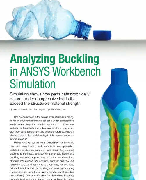
Analyzing Buckling in
ANSYS Workbench Simulation
Simulation shows how parts catastrophically deform under compressive loads that exceed the structure’s material strength.
44 ANALYSIS TOOLS
Parametric Design Analysis for
Evaluating a Range of Variables
Tools help to study engineering trade-offs in Simulation Driven Product Development.
38 36 30
28 MATERIALS
Savings from Submerged
Combustion Melting
Simulation helps glass manufacturers understand complex phenomena in next-generation melter technology.
30 HEALTHCARE
Breathing Easily
Simulation of airflow in human noses can become a useful rhinosurgery planning tool.
3 HEALTHCARE
Ins and Outs of Inhalers
Simulation helps optimize the performance of a dry powder inhaler for drug delivery.
36 OIL AND GAS
Supporting the Oil and Gas Industry
Longevity and safety of drilling derricks and substructures are increased through stress analysis.
41
FEATURE: MULTIPHYSICS
Multiphysics
in Action
Powerful coupled-physics simulation tools solve
demanding applications in a wide range of industries.
By Stephen Scampoli, Multiphysics Product Manager, ANSYS, Inc.
In an expanding range of applications, engineers must be able to accurately predict how complex products will behave in real-world environments in which multiple types of coupled physics interact. Multiphysics simulation is becoming crucial in the development processes for a rapidly growing number of companies. It has the potential to influence engineering simulation efforts in coming years, as more and more companies recognize the strategic value of the technology.
The increased demand for multiphysics simulation is occurring in many different industries as companies strive to maintain a competitive edge. In the electronics industry, high current densities in microchip circuits create large heat loads that need to be dissipated. In the automotive industry, airflow over exterior components, such as side-view mirrors, can create unwanted noise and vibration. In the
bio-stent grafts can be used to improve surgical procedures. In these and a growing number of other applications, multi-physics simulation is rapidly becoming a competitive necessity by allowing engineers and designers to closely evaluate their designs under real-world operating conditions.
Advanced Technology
Multiphysics simulation has been part of the core technology from ANSYS for several decades. From the early versions of the software that included thermal–stress calculations to the recent development of complex thermo-electric–fluidic calculations, ANSYS solver technology has continued to advance the development of state-of-the-art multiphysics solution capabilities.
The functionality of multiphysics technology from ANSYS is unparalleled, with no other solution provider able
Simulation results for a MEMS pressure transducer
Diaphragm Deformation
Electric Potential
Equivalent Stress
FEATURE: MULTIPHYSICS
depth of solution capabilities. Indeed, companies needing true “industrial strength” multiphysics capabilities continue to rely on the complete repertoire of industry-leading functionality from ANSYS.
The current version of ANSYS Multiphysics software has two proven solution techniques for solving coupled-physics problems — directly coupled-field elements and the ANSYS Multi-field solver. These approaches provide flexible simu-lation methods built on proven solver technology to solve a broad range of complex coupled-field problems, such as induction heating, electrostatic actuation, Joule heating and fluid structure interaction (FSI).
Directly Coupled-Field Elements
Directly coupled-field elements allow users to solve coupled-physics problems by employing a single finite element model with the appropriate coupled-physics options set within the element itself. ANSYS coupled-field elements account for coupled physics by calculating the appropriate mathematical terms that include the interaction between the different physics disciplines. In this way, coupled-field element solutions simplify the modeling of a multiphysics problem by allowing users to create, solve and post-process a single analysis model for a comprehensive array of multiphysics problems.
ANSYS coupled-field elements encompass a wide variety of multiphysics analyses including thermal–structural coupling, piezoelectricity, piezoresistivity, the piezocaloric effect, the Coriolis effect (the apparent deflection of moving objects from a straight path when they are viewed from a rotating frame of reference), electroelasticity, thermal– electric coupling and thermal–electric–structural coupling. The broad range of capabilities provided by these elements is essential for the design of many products, such as electronic components, micro-electro-mechanical systems (MEMS), transducers, piezoelectric gyroscopes, accelero-meters and thermoelectric coolers.
In one such application, ANSYS coupled-field elements were used to evaluate the performance of a vibrating silicon ring gyroscope, a particular type of angular velocity sensor
commonly used in automotive braking systems and vehicle stability control systems. The gyroscope is a solid-state device comprising a micromachined silicon ring suspended by surrounding spokes. The ring is excited into a primary mode of vibration and rotated while vibrating, setting up a secondary mode of vibration generated from the Coriolis effect. The angular velocity of the sensor is then detected by sensing the secondary mode of vibration, which is proportional to angular velocity.
One challenge in the design of silicon ring gyroscopes is minimizing energy loss for better sensor performance and lower power consumption. One of the most important
Analysis of the harmonic response of micromachined silicon ring gyroscope, including the effects of thermoelastic damping
Electric potential (top) and equivalent stress (bottom) simulation results for a folded dielectric elastomer actuator
FEATURE: MULTIPHYSICS
energy-loss characteristics to be evaluated in the develop-ment of the device is thermoelastic damping arising from the irreversible heat flow across the temperature gradients induced by the strain field. This effect is characterized by a strong coupling between the structural and thermal fields, accurately represented using matrix coupling in ANSYS Multiphysics software. In this way, the software enabled engineers to minimize energy loss in the gyroscope by evaluating complex mode shapes and the harmonic response of the silicon ring gyroscope while accounting for thermoelastic damping.
Multi-Field Solver
The ANSYS Multi-field solver solves a wide variety of coupled-physics problems by employing implicit sequential coupling. Examples include thermal–structural coupling, thermal–electric–magnetic coupling, electromagnetic– structural coupling and fluid structure interaction (FSI).
With sequential coupling, each physics discipline is solved sequentially, and results are passed as loads from one physics discipline to another with convergence between the individual physics disciplines obtained at each point during the solution. This robust convergence behavior of implicit coupling ensures accuracy and mini-mizes the engineering time needed to achieve valid simulation results.
Since two or more single-physics models are used within the ANSYS Multi-field solver, results can be passed across a dissimilar mesh interface between the physics disciplines. This is a subtle but very important consider-ation, since a dissimilar mesh interface allows a user to optimize the mesh for each individual physics discipline. For example, in a fluid structure interaction problem, the meshing requirements for the fluid are often different from those for the structure. A dissimilar mesh interface also allows independent users to set up their specific physics disciplines, which in turn allows for closer collaboration
between physics experts.
Using such an approach, the ANSYS Multi-field solver was used to evaluate the switching speed of a digital micromirror, a commercially successful MEMs device used as the basis of Digital Light Processing (DLP) technology. In a DLP projec-tor, a projected image is created by an array of several hundred thousand digital micro-mirrors that each alternate rapidly between on and off states, projecting light from the projector into a lens that focuses the pixels on the screen. Held in place by thin tethers, the tiny aluminum mirrors are repositioned during each cycle using electrostatic forces. By sequentially coupling electrostatics and structural deformation in this complex problem, ANSYS Multiphysics soft-ware was instrumental in evaluating the positioning of the digital micromirror as well as the switching
speed of the system.
Another common application of the ANSYS Multi-field solver is fluid structure interaction, which occurs when a fluid interacts with a solid structure causing deformation in the structure and thus altering the flow of the fluid itself. An FSI solution is required for many industrial applications, such as the aerody-namic flutter of airplane wings, transient wind loads on buildings, and biomedical flows involving compliant blood vessels and valves.
For cases such as these, both the structural and fluid solutions must be run concurrently with loads transferred between the two solvers. ANSYS Multiphysics software provides a unique
The switching speed and positioning of a MEMS digital micromirror was studied by sequentially coupling the analysis of models for structural deformation (top) and electrostatics (bottom).
FEATURE: MULTIPHYSICS
Implicit coupling for fluid structure interaction includes iterative analyses of fluid forces that may cause structural reactions, which in turn may alter fluid flow.
ANSYS Multiphysics software was used in optimizing a piezoelectric fan blade geometry to produce a resonant frequency exactly at 60 Hz and in evaluating the motion of the fan blade and resulting air flow.
implicit coupling scheme between these two solutions, in which no third-party coupling soft-ware is required, and each solution is able to run on a separate computer.
Another unique capability of the ANSYS Multi-field solver is the ability to include coupled-field elements within an FSI solution. In one project, coupled-field elements were used in conjunction with the ANSYS Multi-field solver to evaluate the performance of a piezo-electric fan in which the motion of the fan blade is generated by applying a voltage to a piezo-electric material. Often used for spot cooling of electronic components, piezoelectric fans typi-cally consume less energy than conventional fans and do not produce electro-magnetic noise that can interfere with computer circuits. In this device, the fan blade is driven at resonance using a standard AC excitation of 120 volts applied at 60Hz. ANSYS Multiphysics software was used to optimize the size of the fan blade to produce a resonant frequency of the device exactly at 60 Hz and to evaluate the motion of the fan blade and subsequent air flow. This solution required piezoelectricity to be coupled to computational fluid dynamics, which is a unique capability of ANSYS Multiphysics software.
Multiphysics as a Strategic Tool
By using such capabilities, engineers can now perform multiphysics analysis as a routine part of product development. In this way, coupled-physics simulation takes on strategic value in the development of virtual prototypes by accounting for all of the relevant physical phenomena that influence designs.
ANSYS continues to lead the industry in the development of multiphysics solutions that provide the high-fidelity simulations required to meet the challenges of today’s demanding
product development requirements.■
CFD Solution
Structural Solution Displacements
Fluid Forces
5.92e-3 3.65e-3 2.25e-3 1.39e-3 8.6e-4 5.31e-4 3.28e-4 2.02e-4 1.25e-4
31 40 50 60 70 80 90
Frequency (Hz)
Amplitude (m)
-0.849 -25. -50. -75. -100 -125 -150 -179
31 40 50 60 70 80 90
Frequency (Hz)
Phase Angle (
o)
FEATURE: THOUGHT LEADERS
CAE
on the Offensive
A leading Australian aerospace and defense company, Tenix Defence
Pty Limited, reports on computer-aided engineering software trends.
From a naval shipbuilding business in 1997, Tenix Defence Pty Limited has grown to service most areas of the defense industry; it also has established businesses working in aviation, parking and traffic infringement management, commercializing innovative technology and providing engi-neering services for utilities including water, sewerage, gas and electricity. Based in Sydney, Australia, Tenix operates in all mainland Australian states and territories, New Zealand, the South Pacific and Southeast Asia. It is also an active partner in high-technology ventures with United States and
European firms. ANSYS Advantagemagazine interviewed
Peter Wilson, Engineering Manager of Tenix Defence, Electronic Systems Division, and his colleagues about computer-aided engineering (CAE) software trends at Tenix.
Note: Tenix was sold in late January 2008 to BAE Systems, which is Europe’s largest defense company. The acquisition makes BAE the biggest supplier of equipment to Australia’s armed forces.
Q: Who is Tenix and what is its role in the defense industry?
A:Tenix is one of the largest independent defense
contractors and integrators in both Australia and Southeast Asia. There are four major defense businesses: Aerospace, Land, Marine and Electronic Systems. We have other
interests in engineering systems, such as traffic cameras and domestic utilities including waste water treatment and electricity generation.
The company emerged from the industrial construction company Transfield, which was formed in the 1950s. We see our core competence as the ability to be the smartest defense integrators in our segment, and we seek to understand our customers’ individual niche needs. We then work with original equipment manufacturers to deliver best-in-class flexible, customized designs fit for purpose.
Tenix works extensively for the Australian government and other Southeast Asian and Australasian countries providing defense engineering solutions. We currently are building and delivering seven vessels for the Royal New Zealand Navy tailored to their unique systems integration needs. In addition, we work with major defense contractors, such as Lockheed Martin, L3 and Northrop-Grumman, to customize their off-the-shelf defense equipment.
Q: What sort of technical systems integration do you typically perform, and how do computer simulation and CAE feature in your processes?
A:This varies significantly among our defense divisions, and it is best answered on a case-by-case basis, as follows. By Peter Wilson, Engineering Manager, Electronic Systems Division, Tenix Defence, Sydney, Australia
With comments from Fabian Ravalico, Engineering Manager, Land Division, Tenix Defence Kerry Thurstans, Engineering Manager, Aerospace Division, Tenix Defence
Saeed Roshan-Zamir, Structural Engineering Manager, Tenix Marine Division, Tenix Defence
Electronic Systems Division: Peter Wilson, Engineering Manager
The Tenix Electronics Systems Division (ESD) conducts many research and development-type projects. As such, we have a high focus on new design rather than the evolution of existing products and systems. CAE plays an important role in this line of work, as it allows our engineers to communi-cate and deliver designs that, due to their developmental nature, can change rapidly in scope. Our key technology areas, including electronic warfare, high-power lasers and electro-optics, see simulation of fluid flow and thermal inter-actions as a high priority, with structural analysis and modal response being the next most used simulation capabilities.
The tools from ANSYS have already demonstrated benefits: increased confidence in design solutions leading to less conservative designs and reduced solution iterations in the high-technology defense sector in which ESD conducts its business. All of ESD’s mechanical and aeronautical engi-neers now have been trained to use the ANSYS tools. We are part of a powerful community of users among the vari-ous divisions of Tenix that is able to share its experience, ideas and workload.
Land Division:Fabian Ravalico, Engineering Manager
Land Division’s core business is based on the develop-ment, modification, upgrading and through-life support of military and commercial armored vehicles. Product develop-ment traditionally involves physical prototyping followed by testing and introduction of improvements in an iterative manner until the design is mature, verified and validated. The use of modeling and simulation of design concepts via CAE tools leads to accelerated product development lead times; it also reduces the amount of iteration required to reach a mature design. It allows all concepts and design solutions to be considered and assessed for validity in a relatively compressed timescale, enabling progression to a hardware solution (prototype) with high confidence of success. Modeling and simulation are very often more cost-effective than prototyping.
Using Tenix’s new suite of tools from ANSYS, Land Division’s most commonly explored analysis domains are linear analysis, nonlinear analysis, dynamic analysis, crash analysis and blast analysis. Our new challenge is to provide the necessary staff training to capitalize fully on the new tools available.
Marine Division: Saeed Roshan-Zamir, Structural Engineering Manager
We use software from ANSYS extensively to design and assess a large variety of marine structures. This principally involves the solution of load cases, such as shock and airblast, fatigue, vibration and operational loadings at sea. The most notable example is the structural design and analysis of new masts on the ANZAC-class frigates for the Anti-Ship Missile Defence (ASMD) project, which involves the integration of a precision targeting, tracking and illumination
FEATURE: THOUGHT LEADERS
Geometry model for the new mast for ANZAC-class frigates
phased array radar system. Often, we utilize transient simu-lations to model and capture the response of the structure subject to shock pulse accelerations and blast pressures; in addition, we commonly require nonlinear boundary conditions and modal results to capture the natural frequencies of the structure. We employ CAE for our tasks because we require detailed and accurate results in order to effectively optimize our designs. A high percentage of our staff needs to be capable of using the programs effectively — so it’s important for us that the programs can be learned quickly and successfully. We have found software from ANSYS to be highly capable of meeting our needs.
Aerospace Division:Kerry Thurstans, Engineering Manager
Tenix’s Aerospace Division undertakes work in the Australian defense aerospace environment as the lead (or prime) company for the systems integration of avionics, communications, electro-optics, electronic warfare (EW) self protection, and other advanced commercial and military systems. During the design and testing phases of many of our projects, we make extensive use of computer-aided engineering to complement classical analysis and physical testing.
FEATURE: THOUGHT LEADERS
Flow streamlines around a radome (a structural, weatherproof enclosure used to protect an aircraft antenna)
Using a company-wide common toolset, as we have implemented with ANSYS, provides a common training environment, encourages intra-company collaboration and facilitates knowledge transfer.
Q: How do you see your CAE usage evolving in the future?
A:The company’s recent decision to choose simula-tion packages from ANSYS as enterprise-wide CAE tools means that we can improve our productivity and design flexibility like never before for all of our divisions. We selected ANSYS because of the proven performance of the toolset across our broad range of CAE requirements along with the collaborative approach adopted by ANSYS and their Australian agent. We also like the way that we can access a wide range of CAE tools in the one common ANSYS environment, all during the same work session.
One of the benefits of using software from ANSYS in all Tenix divisions is that it allows us to increase and improve our in-house CAE capabilities. We want our existing engineers to use CAE widely. In addition, we intend to hire more engineers to use these exciting new design tools, and the concept of a one-stop design house will certainly be attractive to them.
Going forward, Tenix is looking to increase its capability in analyzing fluid and structure simultane-ously using fluid structure interaction simulations. We certainly have the need to extrapolate existing simulation models with confidence and develop a well-validated set of CAE capabilities.
Q: What does Tenix see as the biggest defense sector CAE challenges for the foreseeable future?
A:Personally, I want Tenix to have a strong integra-tion of the engineering capabilities within all four defense divisions with a close coupling of our techni-cal know-how and expertise. I see CAE as the latest part of that revolution. Already, we have integrated our systems engineering requirements management tools, and product lifecycle management (PLM) is next on our list.
By getting enterprise-wide usage of these same tools, I believe it will lead Tenix to significant produc-tivity gains and efficiency savings as we develop a virtual community of internal users. Over the years, the separate divisions at Tenix have been geographi-cally dispersed across Australia, and they have developed their own expertise. We need to cross-fertilize this CAE knowledge with our deployment of a
common integrated software toolset from ANSYS.■
Stress analysis of a container lock mechanism
Electronic surveillance measure (ESM) antenna mounted onto an aircraft wingtip
FEATURE: CONSUMER PRODUCTS
Global competition in the appliance industry is placing ever-increasing pressure on manufacturers to decrease costs while maintaining high quality. Refrigeration products are especially competitive, and as raw material costs for these appliances continue to rise, manufacturers are forced to take a close look at their product designs.
Keeping Cool
While Cutting Costs
Simulation helps keep temperatures and
costs down while optimizing refrigerator design.
By Axel J. Ramm, Development Specialist - Black Belt, Whirlpool Corporation SA, Latin American Region (LAR), Joinville, Brazil
With worldwide industry revenue in 2006 reported at $6.2 billion and a sluggish market to contend with, the stakes are high.
In an effort to find a competitive edge, Whirlpool Corporation, one of the market leaders in the consumer and commercial refrigeration market, has turned to software from ANSYS.
In the past, cost-reduction projects at Whirlpool typically have required that engineers build and test several prototypes, with results then compared with current production cabinets. This trial-and-error approach is costly and time-consuming, leading to only incre-mental changes. Recently, Whirlpool has enjoyed more substantial benefits
Original design of the Whirlpool refrigerator model used in the cabinet optimization analysis
Finite element model of cabinet and door assembly with close-ups of critical hinges
Upper Hinge
Middle Hinge
FEATURE: CONSUMER PRODUCTS
from an approach that utilizes leading-edge simulation combined with experimental tools to assess complex structural behavior.
When Whirlpool recently looked to cut costs associ-ated with producing a three-year-old, 450-liter double-door refrigerator, the model was required to meet the existing specific cabinet deflection and door drop limits of its current design as well as maintain adequate cabinet stiffness. Cabinet deflection and door drop occur when a fully loaded door is opened. When this occurs, the cabinet distorts and the door moves downward, eventually leading to cabinet deformity. Additionally, any redesign that changes cabinet stiff-ness could negatively impact insulating capabilities as well as aesthetics, which, in the end, can influence consumer-perceived quality.
A refrigerator cabinet is constructed of external sheet metal parts, polyurethane foam filling and internal plastic liners. It is very complicated to evaluate cabinet deflection and door drop since there is significant varia-tion between products of the same model, with variations in both the manufacturing and testing proce-dures affecting door stiffness. To identify the most significant variables, engineers at Whirlpool used Design of Experiments (DOE) and sequential analysis. Following this process and the compilation of quantitative data describing structural behavior, the engineering team then utilized ANSYS Mechanical software to optimize the refrigerator design.
The goal of simulation and analysis was to evaluate the design factors that most significantly affect material costs and door drop. To begin, engineers constructed a finite element model (FEM) of the cabinet using solid and shell elements. (See technical sidebar for details.) All of the finite element analyses (FEAs) executed during this study were performed using ANSYS Parametric Design Language (APDL). The state or response variable used to control the cabinet stiffness was door drop under static load application. The cost function to be minimized was directly related to the mass of the cabinet sheet metal parts.
With the goal of reducing costs by cutting the amount of materials used in manufacturing, the analysis showed that reducing the thickness of the compressor plate, deck reinforcement, bottom deck and front rail (7.8 percent of total mass) would allow for a reduction in materials while having a minimal effect on door drop. The simulation/optimization further determined that the most
Simulation Setup
The refrigerators’ polyurethane foam, EPS mullion, hinges and levelers were modeled with solid tetrahedron elements (SOLID45). Other parts, basically composed of thin plates, were modeled with SHELL181 elements. For all the connections of clinch joints and screws, the element BEAM188 was utilized.
All of the material properties were considered as linear isotropic, and the input data was derived from laboratory tests and supplier technical specifications. For the polyurethane foam, the elastic properties were evaluated in a laboratory test device, and the elasticity modulus was included as a factor.
In order to adequately represent the real loading conditions, the masses of all cabinet parts were evaluated and included. In addition, the masses corresponding to cabinet ballast and loaded doors were calculated and were then assigned to each location in the model. The acceleration due to gravity was applied as a load boundary condition. At its bottom base, the cabinet was constrained, simulating actual operating conditions.
The door attachments and hinges were modeled with constraint equations, which allowed controlling translations and rotations to be correctly transferred from the doors to the cabinet. As a result, it was possible to impose door support only at the bottom position and release rotations from the hinge pins. In so doing, it was necessary to set two additional constraints at the upper liner of each door to eliminate rigid body motion.
Wrapper
Intermediary Rail
Front Rail
FEATURE: CONSUMER PRODUCTS
sensitive factor affecting mass was the cabinet wrapper (or outer paneling), but that reducing the wrapper thickness resulted in an increase in door drop. The most significant factor driving door drop was the screw that connected the intermediary rail and cabinet front flange. In order to compensate for the increase in door drop that resulted from reducing the wrapper thickness, designers added two screw connec-tors, rather than one, between the wrapper front flanges and the intermediary rail, resulting in a 12 percent improvement in door drop. This design change also contributed to cabinet robustness and compensated for polyurethane foam stiffness loss (manufacturing process variation).
In the end, this optimization and the associated design changes resulted in the reduction of overall cabinet mass by 26 percent while maintaining door drop and cabinet displacement at reasonable levels, as defined by Whirlpool quality standards. On the bottom line, material costs were reduced by 15 percent per product, resulting in a cost savings for the company of $1.2 million per year.
By using ANSYS Mechanical software and Six Sigma tools, analysts at Whirlpool now have the ability to develop complex finite element cabinet models calibrated with real data, enabling the optimization of first-round physical prototypes. This procedure has resulted in a reduction of development time and manufacturing costs, helping Whirlpool meet increasingly competitive market requirements.■
Simulation results quantifying door drop (displacement)
Six Sigma and the Importance
of Critical Thinking
In this case study from Whirlpool, Six Sigma tools, includ-ing Design of Experiments (DOE) product testinclud-ing, were used to assess manufacturing process and laboratory test sources of variation affecting cabinet structural behavior. Eventually, engineers gained enough know-ledge to act on variation reduction in order to accomplish the finite element model (FEM) calibration.
With the FEM and calibration completed, the first optimization in ANSYS Mechanical software executed a sequential virtual DOE, with factors and levels selection based on Six Sigma tools. The goal was to evaluate the design factors that most significantly affected door drop and material costs.
At Whirlpool, Six Sigma initiatives are used to investi-gate the impact of sources of variation on key critical outputs of product and process, such as quality or performance, and the initiatives are often lauded for huge reductions in defects. A phrase often associated with Six Sigma philosophy is “Y = f(X)” (Y is a function of X.) This overly simplified equation reflects the obser-vation that behavior in critical product or process performance characteristics (Y) is due to certain process factors or inputs (X). For example, the cabinet wrapper thickness (X) can potentially affect cabinet stiffness and door drop (Y). A crucial part of Six Sigma work is to define and measure variation in Y with the intent of discovering the cause and developing efficient, operational means to control, mitigate or reduce the variation.
In addition, critical thinking based on the scientific method is a very important skill and is used extensively to conduct industrial experiments associated with simulation, which then leads to design optimization. Critical thinking — the process of deduction and induction — implies that the investigator has the wherewithal to develop theories from the initial ques-tions. This wherewithal comprises subject matter knowledge, experience, process knowledge and the ability to reflect critically and engage others. In fact, it has been shown that critical thinking is more important to improvement and development activities than training in a particular tool set.
Whirlpool refrigerator model following a redesign of the doors and some other features but with the same cabinet shape. This model was just launched in the market.
FEATURE: THOUGHT LEADERS
ROTATING MACHINERY: OVERVIEW
As the
World Turns
World conditions and increased competition challenge rotating
machinery designers to deliver higher levels of performance,
efficiency and reliability — faster than ever before.
By Brad Hutchinson, Vice President Industry Marketing, Aerospace and Turbomachinery, ANSYS, Inc.
Spotlight on Engineering Simulation for
Rotating Machinery
Turbomachinery, or more broadly speaking rotating machinery, spans almost all industry sectors and in many plays a vital role. Rotating machines change the state of working fluids (pumps or compressors), convey or transport fluids (fans and pumps), extract energy (turbines) and create propulsion (propellers). Performance, efficiency, reliability and rapid delivery have always been important, but today’s world conditions intensify the pressures designers face.
Currently, the price of oil hovers near $100 per barrel. Concern for climate change is widespread, not only by the general public but also by legislators worldwide. Since
rotating machines play a critical role in power generation and various forms of transportation — and, in some cases, are the limiting factor regarding cost, efficiency and emis-sions — it is natural that they are in the spotlight and the subject of intense analytical scrutiny.
In the energy industries, most of our power is produced by gas, steam and water turbines. Steam turbines extract power in nuclear and coal-fired power plants. Land-based gas turbines, similar to their aeroengine cousins, run on natural gas and, in some cases, oil. Although still relatively small in volume, wind turbine production has increased
Photo © iStockphoto.com/Michael F
ernahl
ROTATING MACHINERY:
OVERVIEW
dramatically in recent years, with the largest machines being 6 megawatts (MW) in size and having rotors approaching 130 meters in diameter. The largest water turbines, such as those used in the Three Gorges Dam in China, have 10-meter diameter runners.
In the transportation industry, turbomachinery plays an equally important role. For air travel, the rotating machinery used on commercial aircraft is well known — the gas turbine aircraft engine. Its key rotating components include the fan, which can be seen when boarding the plane, as well as the compressor and the turbine. Since fuel is a major and often volatile cost for airlines (significantly impacting their profitability) and noise and emissions regu-lations are becoming increasingly stringent, there is a drive for cleaner, quieter and more fuel-efficient engines.
For transportation at sea and on the ground, diesel engines in ships, trucks and an increasing number of cars use turbochargers to improve their performance and efficiency. These engines also use electric-driven fans and pumps, which must be optimized, since available electrical power is limited. Efficiency of the automatic transmission torque converter — another rotating machinery component comprised of a pump, a stator and a turbine — is critical to vehicle fuel efficiency.
Turbomachinery plays an important role in other industries as well. Compressors and pumps are important to the chemical, process, and oil and gas industries, and are even key components in large industrial air conditioning systems. In the medical industry, heart pumps must be designed to be compact and to minimize blood damage.
Each rotating machine type has one or more key design challenges. Cooling due to high temperatures is problematic in gas turbines. Cavitation is an issue in pumps. Non-ideal gas behavior in steam turbines and refrigerant compressors must be considered. In aeroengine fans, noise is a challenge. There
are space limitations when designing automotive fans. For hydraulic turbines, large-scale transient instabilities — also known as vortex ropes — may occur at off-design conditions. These examples indicate the diverse physics requiring consideration for accurate simulation of real machine behavior. In reality, these physical processes interact, and multiphysics analysis increasingly is becoming a requirement for high-fidelity simulations.
Several design, performance or production factors are common among turbomachine types. Reliability and safety require accurate prediction of steady and transient thermal,
Steam turbine simulation plays a key role in enabling designers to improve performance and longevity.
aerodynamic and structural loads for stress and fatigue life predictions. However, excessive safety and strength features are likely to make the machine too expensive or too heavy; these features also can preclude other competing requirements such as efficiency.
Operational cost and emission issues have recently intensified the pressure to produce efficient machines. Time-to-market and cost pressures resulting from competition have underscored the need to “get it right the first time.” These factors, in turn, demand that simulation software provides solutions of ever-increasing resolution and accuracy. Software, when employed in Simulation Driven Product Development (SDPD), helps designers resolve these and other challenges and is a key enabler for reduced-cost, first-to-market rotating machinery development. ■
References
[1] Gerber, A.G.; Sigg, R.; Völker, L.; Casey, M.V.; Sürken, N., “Prediction of Non-Equilibrium Phase Transition in a Model Low Pressure Steam Turbine,”Journal of Engineering for Power and Energy, September 2007, Vol. 221, No. A6, pp. 735–744.
ROTATING MACHINERY:
COMBUSTION LINER
A low-emissions combustion liner is a critical system component for gas turbines. The combustion air in a gas turbine enters through holes in the combustion chamber liner and flows along the liner to keep it cool. Liners are designed to improve durability and cooling while minimizing the flow variation from liner to liner within the same engine. Reducing variation can decrease exhaust temperature spreads, engine hot streaks and emissions. By combining combustion, flow and structural modeling using tools from ANSYS, Power Systems Manufacturing (PSM) in Florida, U.S.A., designs virtual prototypes and avoids expensive physical testing until the very end of the design cycle.
Land-based gas turbines are often used in so-called “peaking” units, when the demand of the electric grid over-whelms the base-load capacity (most often handled by coal or nuclear units). This means that, in order to meet the grid demands but not to exceed them, gas turbine generators often run at partial or varying load. Modern can-annular F Class combustion systems, such as PSM’s Flamesheet, are typically composed of several fuel stages designed to enable the gas turbine to ramp up or down in load during startup and shutdown, or to allow it to run at partial loads.
PSM’s Flamesheet combustor is composed of three separately fueled equiangular circumferential main stages and a pilot stage at the center. The pilot stage is typically operated at low loads, and the main stages are brought online one stage at a time as the turbine ramps up. The combustion liner has only a circumferentially balanced flame during the pilot stage and full-load operation. At part-load conditions, when only one or two of the main stages are on, the flame is located on one-third or two-thirds of the liner inner surface, thereby producing a hot streak along the liner wall.
The high thermal variation and asymmetry on the metal surface of the combustion liners resulting from these hot streaks cause thermally induced stresses. Stresses can lead to thermo-mechanical fatigue that accrues on a cyclic basis and results in low-cycle fatigue failure. If the thermally induced stresses are lower than the yield limit of the material, the cylindrical liners may still deform inelastically due to creep relaxation over time. Liner deformation affects the structural integrity of the combustor as well as the circumferential
which, in turn, can have a negative impact on the unit’s emissions.
Engineers at PSM used a finite element (FE) technique and ANSYS Mechanical soft-ware to design a liner to mitigate such creep ovalization effects. The analysis predicted creep deformation over time of Haynes 230 alloy liner material using inputs from creep specimen testing. The
engi-neers validated these results against field test data of PSM’s Flamesheet combustion liners carried out in a fully-instrumented combustion system of a Siemens Westinghouse SW501F unit at Calpine Corporation’s South Point Plant in Arizona, U.S.A. Similar inspection of 7FA DLN 2.6 combustion system liners also showed signs of creep ovalization.
Diagram of a gas turbine combustor showing locations of burners that are operated depending upon required load. Numbers indicate burners that operate together for the various stages of operation.
3
2 Fuel Nozzles
Liner
3 2 3
Pilot 1
Hot Streaks
and
Deformation
Software tools from ANSYS improve durability
and reduce emissions in gas turbines by helping
to reduce creep in combustion liners.
By J. Page Strohl, Lead Structures Engineering, and Hany Rizkalla, Combustion Structual Design Engineer, Power Systems Manufacturing, LLC, Florida, U.S.A.
ROTATING MACHINERY:
COMBUSTION LINER
Three-dimensional FLUENT computational fluid dynamics (CFD) simulations provided thermal boundary conditions for the FE analysis under part-load operating conditions. Thermal gradients were highest at the premixer exit of the liner’s unsupported forward end, causing it to deform freely and assume a thermally distorted shape.
Next, the engineering team performed a linear elastic analysis on a full 3-D ANSYS Mechanical model that was constrained at the liner lugs to simulate the configuration of the installed engine. They mapped thermal profiles and pressure loads onto the model that were consistent with measured data for a two-stage part-load condition.
They then isolated the stresses caused by the circumfer-ential temperature streak by subtracting the stress due to the radial temperature change from the total outer diameter to inner diameter hoop stress data at the liner premixer axial location. The residual deformation due to the circumferential temperature gradient was isolated in a similar fashion and compared against post-operating inspection data after approximately 20 hours of operation. The linear elastic strains from the 3-D model were used to evaluate the creep strain due to the favorable comparison with experimental data.
Using liner drop measurements separated by several days of operation, PSM engineers found radial ovalization to be approximately 0.78 percent; this indicated creep relax-ation. Furthermore, the creep data for the Haynes 230 example revealed that such creep deformations occurred within the first few hours of part-load operation. The linear elastic stresses were within the elastic yield limit of the liner material. The linear elastic strains associated with these stresses created a strain control environment in which the liner thermal stresses creep relax to the Haynes 230 creep strength capability. Since there are no constant stresses and thermal stresses are within the elastic limit, engineers expect the liners to achieve a permanent set based on the ovalized linear elastic shape and to maintain that thermal shape without further deformation.
Estimating the amount of creep relaxation under strain control (permanent set) in a combustion liner required the use of an FE analysis. Complexity was introduced by 3-D variations in temperature, stresses, creep strain and strain rate across the liner. Specimen lab testing for tensile creep data revealed that the Haynes 230 example exhibited negligible primary creep.
PSM engineers estimated the material constants in Excel through best-fit coefficients to the experimental data. They constructed a complete Flamesheet liner model using 3-D ANSYS SOLID186 element types to simulate the liner’s secondary creep behavior. They mapped temperature and external static pressure loads from the FLUENT results onto the model. The implicit creep routine in ANSYS Mechanical software was invoked by using the strain “rate = 1” option. The ANSYS Mechanical model simulated 25 hours of run time followed by a shutdown, then a restart and continuation up to 1,000 hours of operation followed by a shutdown.
The simulation results showed that the liner mixer exit accumulated approximately 0.55 percent (maximum radial deformation minus minimum radial ovalization) of radial ovalization after 25 hours of part-load operation. After 1,000 hours of operation, the mixer exit accumulated approximately 0.73 percent of diametric ovalization, which compares well with the 0.98 percent of diametric ovalization observed by coordinate measuring machine (CMM) inspec-tion performed on the liner mixer exit after testing. This result also confirmed that the liner creep strain rate decreased as the liner creep relaxed to the desired thermal shape. Although the ANSYS Mechanical creep analysis under-predicts the ovalization, over-firing during testing
This contour plot of temperatures for the liner thermal plot (results for having two main stages on) shows a large circumferential metal temperature gradient on the liner surface over the entire length of the combustor. Orange indicates higher temperature, and blue indicates lower temperature.
The difference between the overall hoop stress (blue, left diagram) and the hoop stress due to radial temperature (red, left diagram) yields the stress caused by the thermal asymmetry (right diagram). The values in the left diagram were calculated based on simulation results using technology from ANSYS.
1.37 1.30
1.20
1.10
1.00
0.90
0.80
0.70
0.60
0.50
0.40
0 800 1600 2400 3200 4000
400 1200 2000 2800 3600
Time (seconds)
25 hrs shutdown ovalization
(x10*3) 1,000 hrs
shutdown ovalization
Radial Ovalization (per
cent)
(max. radial deformation - min. radial deformation)
ROTATING MACHINERY:
COMBUSTION LINER
Simulation results for creep deformation at shutdown after 25 hours of part-load operation (left); 1,000 hours of part-load operation (center) and deformation as measured by CMM inspection after experimental testing (right). Deformed shape is exaggerated in FEA images.
may have caused the liner temperatures to be higher than those predicted by the thermal analysis, resulting in the mismatch.
Using the ANSYS Mechanical simulation to determine the effects of part-load operating hot streaks on the PSM Flamesheet combustor revealed creep relaxation of the liners under a strain-controlled environment. Numerical predictions of the residual ovalization compared well with inspection data on the liner mixer exit obtained from testing. PSM is currently
using ANSYS Mechanical solutions for investigating new designs in order to mitigate such creep relaxations in Flamesheet combustion liners.■
References
Rizkalla, H.; Strohl, P.; Stuttaford, P., “Prediction and Mitigation of Thermally Induced Creep Distortion in Gas Turbine Combustors,” Proceedings of ASME TURBO EXPO 2007: Power for Land, Sea & Air, 2007, GT2007-27815.
ROTATING MACHINERY: COMPRESSOR
The energy industry — particularly the natural gas and hydrocarbon segments — depends on centrifugal compressors to produce, process, liquefy and transport many different gases. As the pressures in a compres-sor increase, the dynamic behavior at shaft and impeller seals, axial thrust balance pistons and impellers becomes more complex, with vibration ultimately becoming a concern.
There are two types of vibration of concern in industrial compressors: synchronous vibration and subsynch-ronous vibration. Synchsubsynch-ronous, or running-speed vibrations, normally are excited by residual unbalance resulting from small imperfections in the manu-facturing and assembly processes. The second and more troubling type of vibration, subsynchronous vibration, occurs when non-conservative whirling forces (cross couplings) act to excite a lateral natural frequency, which occurs in cases in which these fall below run-ning speed. The excitation forces generated at seals and impellers have components that act at right angles to the displacement vector. Cross-coupling effects tend to sustain whirling motion at a subsynchronous natural frequency when insufficient damping is present. The whirling motion is referred to as self-excited rotordynamic insta-bility, and it can lead to serious damage if not properly controlled. Researchers at Southwest Research Institute (SwRI), a nonprofit applied engineering
have examined the possibility that com-putational fluid dynamics (CFD) can be used to study subsynchronous vibra-tions and rotordynamic instability for centrifugal compressors.
A CFD analysis by Moore and Palazzolo[1] used a grid perturbation method (GPM) approach with a 3-D structured computational mesh to demonstrate how cross-coupled stiff-ness for liquid (incompressible) pump impellers could be determined. Gas forces in a compressible fluid tend to be smaller, more difficult to predict and more difficult to model than the liquid forces that were predicted by Moore and Palazzolo. Furthermore, the energy equation and an equation of state are required to completely describe the fluid flow. A lack of accurately predicted operational specifications for compressor designs can result in unexpected, dangerous, and damaging instabilities and subsynchronous vibra-tions, making the identification of accurate analysis methodologies essential to the industry.
Description of Computational Model
A compressor manufacturer provided SwRI with the complete geometry, process and rotor-dynamic information for a centrifugal compressor that previously had experienced subsynchronous vibrations. The centrifugal compres-sor was equipped
had undergone development testing a number of years prior. While testing at a speed of 21,500 rpm and a discharge pressure of 2,300 psi using nitrogen as the testing medium, the compressor encountered classical rotordynamic instability. The frequency corresponded to the first natural frequency of the rotor. A second instability was reached while operating at 23,000 rpm. Engineers at SwRI identified this particular compres-sor as suitable for a case study because the impeller aerodynamic cross coupling was the dominant effect on the machine’s stability. Because the exact conditions at which the compressor went unstable were avail-able from test records, the CFD could be tested under the same conditions.
Innovative Diagnosis
for
Instability in Turbomachinery
Simulation helps to predict subsynchronous vibrations
and rotordynamic stability for centrifugal compressors.
By J. Jeffrey Moore, Program Manager (Rotordynamics Program), Rotating Machinery & Measurement Technology Section, David L. Ransom, Senior Research Engineer, Rotating Machinery & Measurement Technology Section and
Flavia Viana, Research Engineer, Fluid Dynamics & Multiphase Flow Section, Southwest Research Institute, Texas, U.S.A.
Outlet
Sliding Interface
Back Passage
Back Inlet (fluid coming from the hub seal passage)
ROTATING MACHINERY: COMPRESSOR
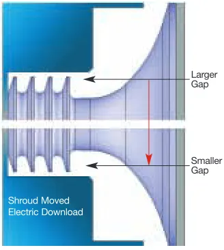
To generate a complete CFD model of this impeller — including both the primary and the secondary flow around the impeller/diffuser, shroud, back face and seals — the engineering team used ANSYS CFX technology. The shroud was displaced in the radial direction. Although the physical prob-lem appeared to be inherently time dependent, a transient CFD solution of this problem was not required if a sim-ple reference frame transformation was performed. Since the shroud region was solved in the whirling frame of reference, while the primary impeller passage was always solved in the rotating frame, a sliding interface was employed. Researchers chose the frozen rotor sliding interface approach exclusively, so as not to artificially con-strain the circumferential pressure field. The rotordynamic influence of the labyrinth seal was modeled in a rotor-dynamics model using a traditional bulk flow seal code.
Researchers evaluated the rotor-dynamic force coefficients of the impeller by determining the impedance at a minimum of three precessional frequencies. For improved accuracy over a wide range of precessional fre-quencies, more than three would need to be calculated and a least-squares curve fit to the linear second-order model was performed. The coefficients of the curve fit would yield the impeller’s stiffness, damping and mass force coefficients.
Validation of Results
In this stage of the project, the team validated the results from the CFD and rotordynamic analyses using real-world data. They used two sepa-rate verification methods for the SwRI CFD model for impeller force work performance. In the first test case, researchers essentially reproduced the results of Moore and Palazzolo[1], though they used an unstructured mesh. This case demonstrated good correlation to previous predictions and experiment, validating the use of an unstructured grid. In the second verification, the team required a comparison of CFD-based stability
The CFD results showed much-improved agreement in overall magnitude in comparison to the appli-cation programming interface API and SwRI methods, which are empirically based equations that have been used in the industry for many years. CFD pre-dicts similar levels of cross coupling for the two instability points, while the empirically based methods do not.
The SwRI team then performed a parametric study to determine the vari-ous parameters known to affect the flow field inside the impeller and their effect on rotordynamic forces. Based on this
Larger Gap Smaller Gap Shroud Moved Electric Download
compressor against measured sub-synchronous vibrations on the test compressor.
Overall, SwRI engineers found the CFD results to be in reasonable agreement with the performance data. The flow field in the secondary passage was highly recirculating. Using a second-order curve fit, the full set of force coefficients was computed. Since the team performed a CFD analysis on only stages one and three, normalized parameters were used to calculate the coefficients for stages two and four. These derived force coefficients were close to the CFD values, validating the method used. Researchers also performed a rotordynamic analysis to analytically determine total dynamic behavior of the rotor at high rotational speeds and the stability of the compressor rotor — including the effects of rotor flexi-bility, bearing stiffness and damping, eye seal stiffness and damping, bal-ance piston stiffness and damping, and aerodynamic excitation.
Engineers analyzed two com-pressor instability cases: instability point one (21,500 rpm) and instability point two (23,000 rpm). Even though the speed increased for point two, the discharge pressure at the point of instability was approximately the same. Therefore, the predicted rotor-dynamic stability varied only slightly between the two conditions. For each case, the aerodynamic cross coupling was varied from 0 to about 25,000 lbf/in to define the slope of the stability curve. The point at which the lines intercepted the vertical axis represented the system
stability without the effects of aerodyn-amic cross coupling. The point at which the lines crossed the horizontal axis was the stability threshold, beyond which the machine was predicted to be unstable. These two lines provided insight into the sensitivity of the rotordynamic stability as a function of aerodynamic cross
Figure 3. Streamlines through stage 1 at the instability point #1, 21,500 rpm
Figure 2. Geometry of compressor under study. Since only shroud forces are of interest in this study, only the shroud region is made eccentric.
ROTATING MACHINERY: COMPRESSOR
Figure 5. Comparison of modally weighted aero cross-coupling values using the various prediction methods
Figure 6. Stability curves for the compressor under analysis and various predicted values for which the compressor would become unstable (i.e., prediction values for where the curves would cross the x-axis of this plot; the CFD results provide the most accurate prediction).
study, they developed a new formula to describe impeller cross coupling. The formula stated that the cross coupling was proportional to the dynamic pressure and the axial length of the impeller, and inversely proportional to relative flow due to the change in the exit flow angle of the impeller, as shown below.
in which
Kxy = cross-coupled stiffness
of impeller (lb/in) [N/m]
Cmr = constant for a given
impeller design
ρdis = discharge density
(lbm/ft3) [kg/m3]
U = impeller tip speed (ft/s) [m/s]
Lshr = axial length of shroud
from impeller eye seal to impeller tip (in) [m] Q/Qdesign = flow relative to design flow
Subsequent studies have indicated that Cmr can vary for different impeller geometries, and it is typically in the range of 4 to 7.5.
As demonstrated in this study, the SwRI engineering team was the first to develop analytical methods capable of analyzing the rotordynamic forces on a centrifugal compressor impeller using CFD. The results compared favorably when predicting the instability of a full-scale compressor. Based on this result, the team concluded that the majority of the destabilizing force of a centrifugal impeller arises from the shroud passage, not the impeller-to-diffuser interaction. These results are described in more detail
in Moore, Ransom and Viana[2].■
References
[1] Moore, J.J., Palazzolo, A.B., “Rotordynamic Force Prediction of Centrifugal Impeller Shroud Passages Using Computational Fluid Dynamic Techniques with Combined Primary/Secondary Flow Model,”Journal of Gas Turbines and Power, Vol. 123, October 2002, pp. 910–918. [2] Moore, J.J.; Ransom, D.L.; and Viana, F.
“Rotordynamic Force Prediction of Centrifugal Compressor Impellers Using Computational Fluid Dynamics,” GT2007-28181, ASME Turbo Expo, May 14–17, 2007, Montreal, Canada.
Method Instability Pt 1 Instability Pt 2
SwRI 18,453 lbf/in 23,441 lbf/in API 13,848 lbf/in 17,301 lbf/in CFD 12,098 lbf/in 11,908 lbf/in
Instability Pt 1
Instability Pt 2
Aero Kxy (N/m)
0.E+00 1.E+06 2.E+06 3.E+06 4.E+06 5.E+06
0.8
0.6
0.4
0.2
0
-.02
0.4
SwRl Pt 1
SwRl Pt 2
API Pt 1 API Pt 2
CFD Pt 1 CFD Pt 2
Log Dec
STAGE 1 CFD Value Applied Cond. Difference
Compressor Speed [rpm] 21,500
Pressure Ratio 1.238 1.264 2.06% Delta Tot. Temperature [F] 40.36 48.10 16.09% Polytropic Efficiency (from Power) 0.746 0.786 5.10% Isentropic Efficiency 0.830 0.779 6.56% Isentropic Efficiency (from Power) 0.736 0.779 5.40%
STAGE 3 CFD Value Applied Cond. Difference
Compressor Speed [rpm] 21,500 21,570
Pressure Ratio 1.234 1.234 0.02% Delta Tot. Temperature [F] 47.60 52.30 9.00% Polytropic Efficiency (from Power) 0.734 0.763 3.80% Isentropic Efficiency 0.815 0.755 7.87% Isentropic Efficiency (from Power) 0.713 0.755 5.66%
ROTATING MACHINERY: TURBINE IMPELLER
High-Speed
Product Design
Integrated software facilitates design and
development of expansion turbines to avoid failure.
By Mike Stanko, Senior Engineering Associate and Michael Chamberlin, Mechanical Design Engineer, Turbomachinery Group, Praxair, Inc., New York, U.S.A.Jeffrey M. Steele, Manager, Software and Services, Impact Technologies, LLC, New York, U.S.A.
turbine impellers, which operate at very high rotational speeds. Impeller aerodynamic performance and relia-bility depend in part upon the impeller blade shape and thickness. In addition to steady-state centrifugal pressure and thermal loads, dynamic stresses arising from upstream flow nozzle pressure fields can cause impeller fatigue failure. The ability to accurately and quickly predict stress, deflection and the modal character-istics of an impeller allows Praxair’s turbomachinery designers to develop an impeller that provides maximum aerodynamic performance without sacrificing reliability.
Praxair engineers use the design analysis package BladePro-CF™ from Impact Technologies, together with mechanical simulation software from ANSYS, to perform steady-state stress analysis, modal analysis (natural frequency and mode shape), harmonic forced response analyses and fatigue life calculations. BladePro-CF is fully integrated with some FEA products
Geometry of the impeller for an expansion turbine
The air separation industry relies on efficient and reliable turbo-machinery to create the highest performance air separation plants possible. Key to this industry are expansion turbines — centrifugal or axial flow turbines that expand a high-pressure gas to reduce the gas tem-perature and produce work. The turbines are widely used for industrial applications that require fluid cooling or low temperature processing. More than 25 years ago,
Praxair, Inc., of New York, U.S.A., a leading supplier of atmospheric, process and specialty gases, created an in-house turbomachinery group that specializes in cryogenic expansion tur-bines. For the last two decades, Praxair turbine design engineers have been using the suite of finite element analysis (FEA) products from ANSYS as their mechanical simulation software pack-ages of choice.
Some of the key components of expansion turbines are radial inflow
CHEMICAL PROCESSING
ROTATING MACHINERY:
TURBINE IMPELLER
Multiphysics, ANSYS Mechanical and ANSYS Structural licenses), making the coordinated use of products relatively simple.
In order to assess an impeller’s margin against fatigue failure, engineers use a combination of steady-state and dynamic stresses. The use of Campbell and interference diagrams, as well as animated mode shapes from BladePro-CF, allows engineers to visualize the potentially dangerous interactions of various impeller mode shapes and sources of excitation.
An analysis begins when Praxair engineers import basic impeller geom-etry data into BladePro-CF. They attach boundary conditions and select materials within BladePro-CF prior to creating the 3-D ANSYS model for simulation. Next, they apply pressure profiles, temperature profiles and the centrifugal load, and the mechanical software from ANSYS calculates the static stress throughout the impeller. Once the static stress analysis is com-plete, engineers examine plots of displacement, von Mises equivalent stress (for crack initiation) and maxi-mum principal stresses (for crack propagation).
The use of a sound mesh topology and a high-density hexahedron-based mesh in the blades and shroud are crucial to accurate frequency prediction for the large number of modes of inter-est. For Praxair’s shrouded impellers, more than 100 modes of vibration are present, ranging from zero rotations per minute (rpm) to the highest frequency of interest. A very accurate representation of stiffness and mass is required to pro-duce sufficiently accurate predictions. The BladePro-CF program pre-selects master degrees of freedom and then allows the Praxair engineers to modify these.
The FEA simulation then calculates the natural frequencies and mode shapes at either zero rpm or a defined speed that would include stress stiff-ening effects. The back-substitution files are saved for any subsequent
harmonic forced response analysis. ANSYS Mechanical simulation results showing maximumprincipal (top) and radial (bottom) stress distributions for important to identify diametral and
circular mode shapes that are critical in assessing the likelihood of dangerous resonance conditions — as not all modes can be excited or are of equal importance.
Engineers next use dynamic forced harmonic response analysis to calculate the dynamic stresses. At this step, a Goodman diagram (available in Blade-Pro-CF) is invaluable, as it provides a graphic display of the combinations of static and dynamic stresses for the entire impeller. The diagram allows a viewer to visually compare the combined stresses with the material’s allowable limits. Once the critical loca-tions are identified, engineers utilize the local strain module of BladePro-CF to calculate the time to crack initiation for each location; this value combined with the duty cycle of the compressor is then used to predict fatigue life.
The Praxair engineering team was able to pinpoint a weakness in an older impeller that experienced a fatigue failure by looking at a Campbell diagram. In so doing, they easily deter-mined that vibration-based failure could be avoided by changing the number of nozzles, or guide vanes, that direct flow to the impeller blades. The analysis portion of this investi-gation took less than a day, compared with multiple days without the use of BladePro-CF and simulation. Impeller failures can cost from $50,000 to $100,000, making the avoidance of these situations of great interest to both the manufacturer and end users.
The combination of BladePro-CF and FEA products from ANSYS allows Praxair engineers to easily and accu-rately determine the quality of their turbomachine impeller designs by pro-viding an appropriate margin against fatigue damage. Using this approach, they can effectively and quickly predict and examine in detail the vibration-related parameters that could affect the reliability and life of their designs. ■
BladePro-CF is a trademark of Impact