?’
Implementation of a Microcontroller Base Single Phase Automatic
Changeover
Oparanwata Chidi Cosmas
Electrical and Electronic Engineering Department Petroleum Training Institute (PTI), Effurun
Delta State, Nigeria. [email protected]
---
************************
---Abstract:
This research work is aimed at automatically switching power between multiple sources in order to provide constant power to load. In Nigeria as a case study, the electric power generated do not meet the demands of the growing consumers of electricity, hence power instability and outage. Power instability or outage normally doesn’t promote development within the public and private sector. The investors don’t feel secure to come back into a country with constant or frequent power breakdown. There are some processes that cannot be interrupted because of their importance like surgery operation in hospitals, transfer of money between banks and lots more. Power instability and outage in countries like Nigeria creates a need for alternative sources of electricity to back-up the mains supply. Automatic changeover switches find application scope wherever the reliability of electrical supply from the utilities is low, for switching to an alternate supply from main source and vice versa.
Keywords — Automatic, Changeover, Source, Switch, Relays, Power, Transfer
---
************************
---I. INTRODUCTION
The need for continuous power supply and its dependability has inflated speedily over the years, particularly in areas where uninterrupted power supply is a must. Modern systems are power dependent. Their complexness has accumulated as continuous information and communications are needed to regulate machine-driven process, be in industrial complexes, hospitals, hotels or perhaps fashionable residences. The need, as such, for independent standby power system has therefore increased greatly.
In the event of power outage, the standby power is most cases expected to start-up automatically. Electrical starting equipment, battery bank and diesel generator are needed for the automated
operation. The automatic transfer is achieved largely by automatic mains failure systems. The process of on-load transfer has to be observed and controlled for a smooth Changeover and within safety limits of all elements of the system. This is achieved by an Automatic Changeover Switch. When the generator is operational, the transfer switch prevents any feedback current to the load.
It additionally ensures that the various power
sources area unit synchronised before the load is
transferred to them. The transfer switch
senses once there's interruption if the
mains provide remains absent. Fluctuations and dip below a specific level inside a mere time within the mains provide will cause the automated transfer switch to transfer the load to the generator.
The turning on of the generator is carryout by a relay that switches the battery voltage to the ignition coil of the generator. In some seconds when the generator is producing maximum power, the transfer switch disconnects the load from the mains supply and connects it to the generator supply, restoring electricity to the load. The changeover switch continues to watch the mains supply and when it is restored, it switches the load from the generator back to the mains. Once the generator is disconnected, it goes through a relax routine and shuts down on its own.
A. Aims And Objectives
The automatic changeover switch is designed to automatically switch over to the alternative sources of supply (generator) when there is a failure on the mains source. It equally switches over the mains supply when power is restored. Due to the rate at which more sophisticated electrical and electronic gadgets/appliances are being procured and installed in our homes, hospitals and industries, there’s a excusable need for a quicker and more reliable changeover system in an event of power outage. The automatic changeover switch is aimed at achieving the following automatic actions;
1. To change mains power over to generator.
2. To change power back to the mains.
B. Applications of Automatic Change Over Switch
An automatic change over switch finds its relevance in the following areas;
1. In HOSPITALS; to ensure uninterrupted power supply during surgical operation and other emergency situation.
2. In BANKS; to ensure uninterrupted cash transactions and other services rendered by the bank. 3. It is used in areas where the reliability of electrical power supply is low.
4. In areas where lifts and elevators are being used.
II. METHODOLOGY
The methodology adopted in the implementation of this research work is top down method. The microcontroller based 100A Automatic Change Over was divided into five (5) units for simplicity and efficiency. Below are the following units of the design:
• The power supply unit
• The Mains detection Unit
• The Generator Feedback Unit
• The Generator Ignition OFF/ON Unit
• The Generator Starter Coil Control Unit
• The Switching Unit
• The Indicator Unit
• The Alarm unit
• The Microcontroller Unit
GENERATOR FEEDBACK
MICROCONTROLLER
POWER SUPPLY
ALARM UNIT UNIT
INDICATOR UNIT
SWITCHING UNIT
GENERATOR IGNITION
GENERATOR STARTER MAINS DETECTION
UNIT
UNIT
OFF/ON UNIT
CONTROL UNIT UNIT
Fig: 1: A block diagram of a Microcontroller Base Single Phase Automatic Changeover
Also the methodology adopted for the software development is the:
• The Algorithm Generation
• The Coding.
III. SYSTEMDESIGNAND
IMPLEMENTATION
A. Hardware Design Specification
The design has the following overall specifications
• Operating Input Voltage: 220/240V.
• Power Sources: PHCN and Generator
• Phase: Single
• Load Max. Current: 100A
• Switching Component: Two (2) 50A
Contactor
• Operating Power Frequency: 50Hz.
• Controller Used: PIC16f877A
Microcontroller from Microchip Corporation.
• Audible Indication: 5-12v DC Buzzer Alarm
• Features: Automatically OFF and ON the
Generator; Microcontroller is Battery Powered; Generator Kick Indicator LED; Switch to MAINS delay LED.
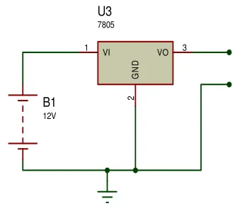
B. The Power Supply Unit
This unit provides the power requirements of the components in the circuit. The Generator 12V Battery connected to a LM7805 voltage regulator was used to power the circuit. This is because the circuit design requires a stable power source independent from the MAINS and GENERATOR sources.
B1
12V
VI
1 VO 3
G
N
D
2
U3
7805
Fig. 2: Power Supply Unit
C. The Mains Detection Unit
This unit serves the purpose of interrupting the Microcontroller on MAINS Voltage detection. The unit provides 5V DC to the microcontroller unit on MAINS Detection. It was implemented with the following components:
• 220V/12V step down transformer
• Bridge Diode
• Capacitor
• Voltage regulator
Below is the circuit diagram of the power supply unit:
TR2
TRAN-2P2S
BR2
BRIDGE
C3
2200uF 35v
VI
1 VO 3
G
N
D
2
U6
7805
POWER SUPPLY UNIT
Fig. 3: The Mains Detection Unit
1. Voltage regulator: As we require a 5V we need LM7805 Voltage Regulator IC.
7805 IC Rating:
• Current rating Ic = 1A
• Output voltage range VMax=5.2v and VMin = 4.8v
2. Transformer: Selecting a suitable transformer is of great importance. The current rating and the secondary voltage of the transformer is a crucial factor.
• The current rating of the transformer
depends upon the current required for the load to be driven.
• The input voltage to the 7805 IC should be
at least 2V greater than the required 2V output, therefore it requires an input voltage at least close to 7V.
• So I chose a 12-0-12 transformer with
current rating 500mA (Since 12*√2 = 16.97V).
3. Rectifying circuit: The best is using a full wave rectifier
• Its advantage is DC saturation is less as in
both cycle diodes conduct.
• Higher Transformer Utilization Factor
(TUF).
• 1N4007 diodes are used as it is capable of
withstanding a higher reverse voltage of 1000v whereas 1N4001 is 50V
• Center Tap Full Wave Rectifier
The bridge rectifier converts the ac voltage input to dc voltage at its output.
The choice of the bridge rectifier depends on:
i. Peak inverse voltage.
ii. The forward current rating
The diode forward current rating is the maximum that the diode can conduct before failing. The diode should be selected in such a way that the current
passing through it should be less than the
forward current rating. The peak inverse output is
the reverse voltage that the diode has to block when not conducting.
Peak inverse voltage = 2 x Vrms
where Vrms = transformer output
= 12Vac
∴ peak inverse voltage = 2 x 12 = 16.97V
∴ The diodes used has forward current ≥
500mA and PIV ≥ 16.97V The diodes IN4007 was used.
D. The Generator Feed Back Unit
This unit signals the microcontroller when there is power supply from the GENERATOR. It enables the microcontroller to automatically Key start the generator as well as OFF the generator. It gives 5V DC to PIN20 of the Microcontroller Unit when the generator supplies output voltage.
It was implemented with the same components in the MAINS Detection Unit.
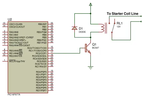
E. The Generator Ignition OFF/ON Unit
RA0/AN0 2 RA1/AN1 3 RA2/AN2/VREF-/CVREF 4 RA4/T0CKI/C1OUT 6 RA5/AN4/SS/C2OUT 7 RE0/AN5/RD 8 RE1/AN6/WR 9 RE2/AN7/CS 10 OSC1/CLKIN 13 OSC2/CLKOUT 14 RC1/T1OSI/CCP2 16 RC2/CCP1 17 RC3/SCK/SCL 18 RD0/PSP0 19 RD1/PSP1 20 RB7/PGD 40 RB6/PGC 39 RB5 38 RB4 37 RB3/PGM 36 RB2 35 RB1 34 RB0/INT 33 RD7/PSP7 30 RD6/PSP6 29 RD5/PSP5 28 RD4/PSP4 27 RD3/PSP3 22 RD2/PSP2 21 RC7/RX/DT 26 RC6/TX/CK 25 RC5/SDO 24 RC4/SDI/SDA 23 RA3/AN3/VREF+ 5 RC0/T1OSO/T1CKI 15 MCLR/Vpp/THV 1 U2 PIC16F877A Q1 BC547 RL1 12V D1 DIODE 12V Vcc
To Ignition Line
Fig 4: The generator ignition OFF/ON Unit
F. The Generator Starter Coil Control Unit
This unit enables the microcontroller to control the generator starter coil so as to start the Generator. It was also implemented a transistor switch circuit. The Terminals of the Starter coil passes through the RELAY. Below is the interface between the microcontroller and this unit.
RA0/AN0 2 RA1/AN1 3 RA2/AN2/VREF-/CVREF 4 RA4/T0CKI/C1OUT 6 RA5/AN4/SS/C2OUT 7 RE0/AN5/RD 8 RE1/AN6/WR 9 RE2/AN7/CS 10 OSC1/CLKIN 13 OSC2/CLKOUT 14 RC1/T1OSI/CCP2 16 RC2/CCP1 17 RC3/SCK/SCL 18 RD0/PSP0 19 RD1/PSP1 20 RB7/PGD 40 RB6/PGC 39 RB5 38 RB4 37 RB3/PGM 36 RB2 35 RB1 34 RB0/INT 33 RD7/PSP7 30 RD6/PSP6 29 RD5/PSP5 28 RD4/PSP4 27 RD3/PSP3 22 RD2/PSP2 21 RC7/RX/DT 26 RC6/TX/CK 25 RC5/SDO 24 RC4/SDI/SDA 23 RA3/AN3/VREF+ 5 RC0/T1OSO/T1CKI 15 MCLR/Vpp/THV 1 U2 PIC16F877A Q1 BC547 RL1 12V D1 DIODE
To Starter Coil Line
Fig 5: The Generator Starter Coli Unit
F. The Switching Unit
The Switching unit consists of a 100A Contactor, a relay coupled to the collector a transistor in common emitter mode used to switch the Contactor. This configuration switches between the generator and public supply lines (MAINS), making use if the
normally open and normally closed terminals of the relay. The base of the transistor is connected to the microcontroller through a biasing resistor, Rb. A diode is connected across the 12 V line and the collector in reversed biased mode to prevent back EMF that might be generated from the relay coil. The circuit is shown below.
1. Selection of the Transistor
The choice of Q1 depends on the following
parameters:
• The nature of the actuating signal (control
signal).
• The load current demand (collector current)
• The supply voltage.
The relay current (load current)= Relay voltage/ Relay resistance
Relay voltage=12V (specified) Relay Resistance= 120Ω (observed)
Relay current demand= 12v/120 =0.1A i.e. 100mA. Relay current=transistor collector current.
From the bc547 datasheet, Ic (sat) = 400mA >
100mA (load).
Hfe= 100 to 150; using a Hfe of 120 Vbe=0.7v.
From the switching analysis of a transistor: Ibsat=Icsat x hfe; Icsat=400mA; hfe=120;
Ibsat=(400x10-3)/120 = 3.33mA.
Calculating for RB Vp - Ibsat x Rb – Vbe = 0;
Rearranging the equation: Rb = (Vp-Vbe)/Ibsat
From the datasheet of PIC16f877A microcontroller Vp=4.3v;
Rb= (4.3 – 0.7)/0.0033 = 1080Ω. A standard value of 1KΩ was used.
G. The Indicator Unit
- Generator Kick Indication
- MAINS input Delay Indication
Two LEDS was used to implement this unit. The LEDS was connected directly to the microcontroller unit through PIN39 and PIN40. Below is the
interface between the LEDS and the
microcontroller unit. RA0/AN0 2 RA1/AN1 3 RA2/AN2/VREF-/CVREF 4 RA4/T0CKI/C1OUT 6 RA5/AN4/SS/C2OUT 7 RE0/AN5/RD 8 RE1/AN6/WR 9 RE2/AN7/CS 10 OSC1/CLKIN 13 OSC2/CLKOUT 14 RC1/T1OSI/CCP2 16 RC2/CCP1 17 RC3/SCK/SCL 18 RD0/PSP0 19 RD1/PSP1 20 RB7/PGD 40 RB6/PGC 39 RB5 38 RB4 37 RB3/PGM 36 RB2 35 RB1 34 RB0/INT 33 RD7/PSP7 30 RD6/PSP6 29 RD5/PSP5 28 RD4/PSP4 27 RD3/PSP3 22 RD2/PSP2 21 RC7/RX/DT 26 RC6/TX/CK 25 RC5/SDO 24 RC4/SDI/SDA 23 RA3/AN3/VREF+ 5 RC0/T1OSO/T1CKI 15 MCLR/Vpp/THV 1 U2 PIC16F877A R2 10k R3 10k D3 DIODE-LED D4 DIODE-LED
Fig 6: The Indicator Unit
Imax = 12mA - 10mA Voltage drop (Vd) = 0.6v PD (max) = 15mW at 250C
R1 is a limiting resistor that limits the amount of current flowing across the diode.
R1 = (Vs - Vd) / Imax Where Vs is source voltage Vd is voltage drop
Imax is maximum current
R1 = (5 – 0.6 x 10³)/12 = 1075Ω. A standard of 10K Resistor was used.
H. The Alarm Unit
This unit gives an audible sound/alert for five seconds on detection of the mains voltage. It was implemented with a 3-25v dc buzzer connected directly to the microcontroller. It was biased with a transistor and a 10k resistor to limit current from the controller to the base of the transistor. Below is
the interface between buzzer and the
microcontroller. ALARM UNIT DC BUZZER DO Q2 BC547 R2 10k 12V RA0/AN0 2 RA1/AN1 3 RA2/AN2/VREF-/CVREF 4 RA4/T0CKI/C1OUT 6 RA5/AN4/SS/C2OUT 7 RE0/AN5/RD 8 RE1/AN6/WR 9 RE2/AN7/CS 10 OSC1/CLKIN 13 OSC2/CLKOUT 14 RC1/T1OSI/CCP2 16 RC2/CCP1 17 RC3/SCK/SCL 18 RD0/PSP0 19 RD1/PSP1 20 RB7/PGD 40 RB6/PGCRB5 39 38 RB4 37 RB3/PGM 36 RB2 35 RB1 34 RB0/INT 33 RD7/PSP7 30 RD6/PSP6 29 RD5/PSP5 28 RD4/PSP4 27 RD3/PSP3 22 RD2/PSP2 21 RC7/RX/DT 26 RC6/TX/CKRC5/SDO 25 24 RC4/SDI/SDA 23 RA3/AN3/VREF+ 5 RC0/T1OSO/T1CKI 15 MCLR/Vpp/THV 1 U4 PIC16F877A
Fig 7:The Alarm Unit
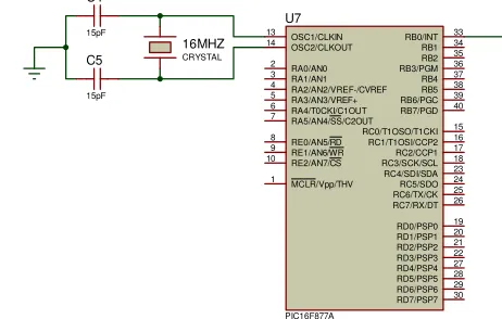
I. The Microcontroller Unit
The microcontroller unit circuit is the heart of the project. This is where the program for the control part of the project is written and burned using C language and a universal programmer, respectively. The circuit diagram is as shown
RA0/AN0 2 RA1/AN1 3 RA2/AN2/VREF-/CVREF 4 RA4/T0CKI/C1OUT 6 RA5/AN4/SS/C2OUT 7 RE0/AN5/RD 8 RE1/AN6/WR 9 RE2/AN7/CS 10 OSC1/CLKIN 13 OSC2/CLKOUT 14 RC1/T1OSI/CCP2 16 RC2/CCP1 17 RC3/SCK/SCL 18 RD0/PSP0 19 RD1/PSP1 20 RB7/PGD 40 RB6/PGC 39 RB5 38 RB4 37 RB3/PGM 36 RB2 35 RB1 34 RB0/INT 33 RD7/PSP7 30 RD6/PSP6 29 RD5/PSP5 28 RD4/PSP4 27 RD3/PSP3 22 RD2/PSP2 21 RC7/RX/DT 26 RC6/TX/CK 25 RC5/SDO 24 RC4/SDI/SDA 23 RA3/AN3/VREF+ 5 RC0/T1OSO/T1CKI 15 MCLR/Vpp/THV 1 U7 PIC16F877A 16MHZ CRYSTAL C4 15pF C5 15pF
Fig. 8: The Microcontroller Unit
The sequence of operation of the circuit is as follows
• On power ON, initialize the internal
variables and TEST indicator and alarm unit by blinking it three times.
• Test if MAINS supply is present by the
Alarm unit and the Delay LED for five seconds.
• Switch to MAINS by activating the
switching unit.
• OFF Generator by deactivating the
Generator ignition OFF/ON unit.
• If MAINS is OUT, enable the ignition
OFF/ON unit, enable the generator starter unit and Kick LED for 5 seconds, and then deactivate it again. Repeat process for three times. If between the three times the Generator feedback unit does not respond, indicate fault by activating the alarm unit and the indicator unit.
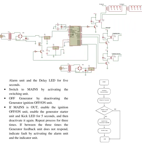
Fig.9: Circuit Diagram of a Single Phase Automatic Changeover
J. Flow Chart
The flow chart gives a graphical representation of the sequence of program execution. The flow chart is given below:
Fig. 10: Flow Chart
Circuit Operation
The sequence of operation of the circuit is as follows
• On power ON, initialize the internal
variables and TEST indicator and alarm unit by blinking it three times.
RA0/AN0 2
RA1/AN1 3
RA2/AN2/VREF-/CVREF 4
RA4/T0CKI/C1OUT 6
RA5/AN4/SS/C2OUT 7
RE0/AN5/RD 8
RE1/AN6/W R 9
RE2/AN7/CS 10
OSC1/CLKIN 13
OSC2/CLKOUT 14
RC1/T1OSI/CCP216 RC2/CCP117 RC3/SCK/SCL18
RD0/PSP019 RD1/PSP120 RB7/PGD 40 RB6/PGCRB5RB4393837 RB3/PGMRB0/INTRB2RB1363534 33
RD7/PSP730 RD6/PSP629 RD5/PSP528 RD4/PSP427 RD3/PSP322 RD2/PSP221 RC7/RX/DT26 RC6/TX/CKRC5/SDO2524 RC4/SDI/SDA23 RA3/AN3/VREF+ 5
RC0/T1OSO/T1CKI15
MCLR/Vpp/THV 1
U1
PIC16F877A
16MHZ
CRYSTAL
C1
15pF
C2
15pF
V2
MAINS
220V AC 1VI VO3
G
N
D
2
U6
7805
11 12 TR2
TRAN-2P2S
BR2
BRIDGE
C3
2200uF 35v
Q2
BC547
R1
10k
BUZ1
BUZZER
Q1
BC547
R9
10k
RL1
12V
D1
DIODE
12V Vcc
Nuetral (AC)
TO 220V AC TO 220V AC
B1
12V VI
1 VO 3
G
N
D
2
U3
7805
Q1
BC547
RL1
12V
D1
DIODE
12V Vcc
To Ignition Line
Q1
BC547
RL1
12V
D1
DIODE
12V Vcc
To Starter Coil Line
V2
Generator Supply 220V AC
TR2
TRAN-2P2S
BR2
BRIDGE
C3
2200uF 35v
VI
1 VO 3
G
N
D
2
U4
• Test if MAINS supply is present by the
MAINS Detection unit, if MAINS, activates Alarm unit and the Delay LED for five seconds.
• Switch to MAINS by activating the
switching unit.
• OFF Generator by deactivating the
Generator ignition OFF/ON unit.
• If MAINS is OUT, enable the ignition
OFF/ON unit, enable the generator starter unit and Kick LED for 5 seconds, and then deactivate it again. Repeat process for three times. If between the three times the Generator feedback unit does not respond, indicate fault by activating the alarm unit and the indicator unit.
IV. RESULT
When mains supply is available, the test carried out was to ascertain the ability of the circuit to detect or sense mains power supply and switch from the alternative power supply to mains. The ability of the circuit to return to alternative power supply, when mains supply is absent was also confirmed. The circuit was also tested for consistency of operation and predictability in delay and switching times. These were also found to be satisfactory. The alarm circuit and light indicators also performed satisfactorily when different power sources were available
V.CONCLUSIONS
A successfully research microcontroller-based
automatic power changeover with artificial
intelligence for auto switching from conventional source to alternative source and vice versa, in the event of power failure. This system has two major sensors; one for the public power supply and the other for the standby generator
ACKNOWLEDGMENT
My gratitude to God almighty for the strength He gave to complete this research work and also to my family for be there for me.
REFERENCES
[1] https://www.modishproject.com/design-construction-automatic-single-phase-changeover-switch/