A Modeling & Simulation Implementation Framework
for Large-Scale Simulation
Song Xiao
1,*, Teng Da
1, Qian Lidong
1, Shi Xuecheng
11
Science and Technology on Aircraft Control Laboratory, School of Automation Science and Electrical Engineering, Beihang University, Beijing, China
Received 15 July 2012; received in revised form 30 August 2012; accepted 29 September 2012
Abstract
Classical High Level Architecture (HLA) systems are facing development problems for lack of supporting
fine-grained component integration and interoperation in large-scale complex simulation applications. To provide
efficient methods of this issue, an extensible, reusable and composable simulation framework is proposed. To
promote the reusability from coarse-grained federate to fine-grained components, this paper proposes a modelling &
simulation framework which consists of component-based architecture, modelling methods, and simulation services
to support and simplify the process of complex simulation application construction. Moreover, a standard process
and simulation tools are developed to ensure the rapid and effective development of simulation application.
Keywords: simulation environment, HLA federate, component, system architecture
1.
Introduction
The modeling and simulation technology is widely used in many fields such as industry, scientific research and military
analysis. As the simulation applications become more and more complicated, constructing these systems become more
difficult. There are measures to simplify the simulation development. Standard process models, such as Distributed Simulation
Engineering and Execution Process (DSEEP) [1], define common, unified process models, which provide a common
framework for different communities to describe their engineering practices, so the engineers can communicate with each
other well.
And standard simulation interoperation protocols, such as HLA [2], DIS [3] and TENA [4] provide common distributed
interoperation methods between different member applications, so subsystems can be composed to construct a more complex
simulation system. This paper presents a simulation environment, which is intended to utilize the best practices in the field of
simulation to support simulation applications for large-scale complex system.
The rest of this paper is organized as follows. Section 3 provides a brief introduction to the whole simulation
development process and the architecture of the simulation environment. Simulation model components are discussed in
Section 4, including the definition of components and how to compose these components. In Section 5, simulation services are described, which form the runtime for simulation models. At the last runtime, object database is presented in Section 6, which
International Journal of Engineering and Technology Innovation, vol. 2, no. 4, 2012, pp. 265-272 266
2.
Related Work
Large-scale simulation requires advanced implementation simulation software approaches. Many pioneering works
have been done to construct the theory base, including [1-6]. However, most of the works are focused on simulation process
and components theoretic methods while they are lack of implementation techniques.
[11-12] proposed cell-DEVS and developed CD++ tools, which is open source and supporting discrete event system
modeling and simulation. [13] designed HyperWarpSpeed time management algorithms, developed parallel simulation engine
and used the engine in military simulation systems. [14] developed simulation engine GTW and the product named FDK, using in multi-field including biology, physiology, traffic and communication etc. All the works are useful for reference. However,
they did not address the scheduling service management of local multi-components.
Moreover, HLA is also recognized with its low running efficiency because of losing fine-grained component integration
and interoperation in local HLA federates. Here we have an underline prerequisite is that a lower HLA federation is made slow
for the lowest federate waiting by other federates. Therefore, to provide more efficient methods of this issue, an extensible,
reusable and compensable simulation framework is proposed in this paper and we start discussing the development of a
promoted and standardized process and architecture.
3.
Process and Architecture
A standard process can provides a common language for simulation developers to communicate and gives a better understanding to the life-cycle of the simulation application. To suit this component-based simulation environment, a process
is proposed which tailored and specialized from DSEEP. The process is summarized as follows.
Step 1: Define simulation application objective. The user, the sponsor, and the development/integration team define and
agree on a set of objectives and document what must be accomplished to achieve those objectives.
Step 2: Perform conceptual analysis. Scenario development and conceptual modeling take place in this step. The output
including scenarios and conceptual models guides the rest of the development process.
Step 3: Design simulation application. Existing simulation model components which are reusable is selected, and new
components are designed. Component model is described in the next section.
Step 4: Develop simulation application. The new simulation model components are implemented, and data exchange
model is developed for Runtime Object Database.
Step 5: Integrate and test simulation application. Simulation model components are composed to form simulation
entities, and simulation services suitable for this simulation are selected and integrated.
Step 6: Execute simulation and analyze results. The simulation is executed and output data from the execution is
collected and analyzed.
The scenarios, conceptual models and model components created in the process can be stored in repositories for reuse in
other simulation applications.
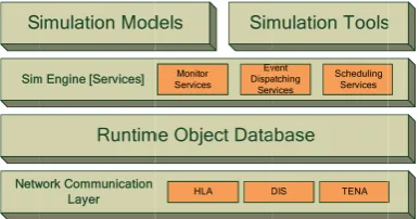
In the simulation environment, common simulation services are provided to form the simulation runtime, so the
simulation application developers can focus on simulation modeling. The simulation environment consists of four layers,
.
Simulat
Compone
ots of advantag
ways to simula
omponents), a
o be flexible c
apidly assemb pplications can Conceptu utputs, conten omponent arch ommunicate.
escribed in the
n DEVS [6], a
M X
where X is the s
i
nce last trans
nvironment, X
, , ta are
1. Interfaces An interf
ervice through
o reuse and ext
2. Events The notio
ventSink. Com
tion model
ent-based com
ges compared
ate complex s
and then comp
configured to a
le and configu
n vary in not o
ual model is a
nts, assumptio
hitecture, it is
So the conce
e following pa
discrete even
int
, , , , ext
X S Y
set of input va
is the external
sition;
X and Y are ma
e translated to
face declares a
h the operation
tend compone
on of events
mponents whic S Netw Sim F
component
mposability isto large granu
system is bre
posing them to
adapt to a ran
ure a unique
only scenarios
a non-softwar
ons and simp
vital to model
eptual model
aragraphs.
nt system is pr
, , ta
alues; S is a se
l transition fun
is the outpu
apped to interf
implementati
a set of operati
ns of this interf
ents as the wh
is also descri
ch support eve
Runtim imulation Mod
work Communication Layer m Engine [Services]
Fig. 1 Simulati
ts
one of the key
ular models. Fo
aking the sys
ogether to form
nge of mission
simulation sy
s but also beha
re description
lifications of
l component d
formalism is
resented as
et of states; Y i
nction, where
ut function;
faces and even
ons of compo
ions that a clie
face. Compon
hole system is
ibed by interf
ents must impl
me Object Data
dels Sim HLA Monitor Services Ev Dispa Ser ion environm
y features of t
or example, th
stem into sma
m the whole sy
ns, scenarios a
ystem from ex
aviors.
of the compu
f the model [8
development b
briefly introd
is the set of ou
is
nts of compon
onents.
ent may reque
nents commun
described by
faces. There a
lement one or
abase mulation Tools DIS TENA vent atching vices Scheduling Services ent architectu the simulation
hey are easy to
aller sub mod
ystem. Compo
and simulation
xisting simulat
uter simulatio
8][9]. Althoug
because it restr
duced here; a
utput values;
the set positi
ents, S are ma
st. A compone
icate only thro
interfaces not
are two speci
r both of them. re
n environment
o understand an
dels (also refe
osability refers
n models [7].
tion componen
on model, des
gh conceptua
rains what the
and how it is
is th
is the total s
ve reals with
apped to prope
ent which sati
ough interface
t specific comp
ific interfaces
An event sou
t. Small granu
and develop. S
erred to as si
rs to the ability
With compos
ents. These cre
scribing the o
al model is no
e components
converted to
he internal tran
state set , e is
h 0 and
. Inerties of comp
isfies the inter
es they implem
mponents.
s which are E
urce embodies
ular models ha
o one of the b
mulation mod
y of a simulati
sability, one c
eated simulati
bjective, inpu
ot a part of t
do and how th
o components
nsition functio
the time elaps
n the simulati
onents, and
rface provides
ment, so it is ea
EventSource a
International Journal of Engineering and Technology Innovation, vol. 2, no. 4, 2012, pp. 265-272 268
interface EventSource {
Events getEvents();
}
interface EventSink {
void pushEvent(in Event e);
}
The event dispatch strategy is not specified by the components but decided when composing the components into a
system. Two dispatch strategies are provided by now, and more can be added. To solve the problem of confliction, each type of
events can only has one dispatch strategy. The publish/subscribe strategy is that the event sources, sinks publish, subscribe
types of events, and event dispatching service transmits the specified types of events from publishers to subscribers. The
connect strategy is defined by connections between components with each connection linking two components. Events are
transmitted through the connections.
4.3. Components
There are two types of DEVS components: atomic components and composed components [6]. A composed component
consists of atomic components and/or other composed components, while atomic components cannot be divided into smaller parts.
The definition of a component includes interfaces, references, input events and output events. Interfaces indicate the
operations provided by this component. References are connection points to other components, so this component can use
services supplied by the referred object. Input and output events are the types of events used to communicate with other
components.
4.4. Component Composition
Component composition is implemented by references which link to subcomponents. References to other components
are usually though not specific components but interfaces. The component can refer to any component which satisfies the
specified interface. Component connections are specified by an assembling script based on XML. The script describes which
instances of components are in the system, their initialization parameters and how they connect to each other.
In this simulation environment, simulation entity is a kind of component, which satisfies special constrains including the
initial parameter loading interface and simulation engine event interfaces. Simulation entities are relatively independent
components, because they do not have references to other components and they communicate only through events. Simulation
entities are the smallest process units scheduled by the simulation runtime.
5.
Simulation services
5.1. Simulation Engine
Simulation services forms Simulation engine, which includes simulation monitor service, time management service,
event dispatching service and simulation scheduling service. The engine drives simulation models to advance the simulation
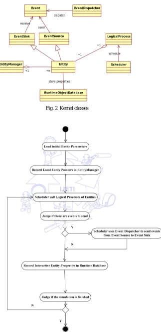
and generate output data. The kernel classes of the simulation engine are shown in Fig. 2.
Entity and Event are the fundamental elements of discrete event simulation. Events are passed form Event Sources to
Event Sinks by Event Dispatcher. Scheduler manages Logical Processes which manipulate the runtime states of the Entities.
Fig. 2 Kernel classes
Fig. 3 Running Process of Simulation Engine
LogicalProcess Event
Entity EventSink
Scheduler EntityManager
EventDispatcher
EventSource
+1
+1 send
receive
schedule
+1 +n
dispatch
International Journal of Engineering and Technology Innovation, vol. 2, no. 4, 2012, pp. 265-272 270
5.2. Simulation Monitor Service
Simulation monitor service controls the working state of the simulation engine. These states include the initializing,
suspending, running, saving, restoring and terminating states. After the simulation engine has been initialized, it goes
automatically into the suspending state. In the simulation process, the engine can be in suspending or running state, controlled
by the commands from the client. When the simulation terminating condition is satisfied or the monitor receives terminating
commands, the simulation engine goes into terminating state, and the simulation process finishes.
5.3. Event Dispatching Service
The notion of events has been introduced above, and two event dispatch strategies between components have been
proposed. At the inter-entity level, a third strategy is provided to enrich the semantics of events. As each simulation entity has
a unique identifier, so simulation entities can send events to the certain entities which they want to communicate with by using
this unique identifier. The types of events using this dispatch strategy must have an identifier to indicate the event target and a time tag, and the events are delivered to the target specified by target identifier and sorted by the time tag. More strategies can
be added at the inter-entity level, and events must register their dispatch strategies before simulation starts.
5.4. Scheduling Service
Scheduling service is responsible for scheduling simulation models to processing units. There are two ways which are serialization and parallelization to do this. Serialization way is relatively simpler and runs faster on single processing unit,
while parallelization way is more effective on multiple processing units, because it can utilize the parallel computation
capability of multi-processors.
The simulation entities are processed one by one in the serialization method, which is described as follows.
for each simulation entity Entityi {
for each simulation event Eventij of Entityi {
process Eventij
} }
The parallelization method consists of a monitor thread and multiple worker threads. The monitor thread is responsible
for computation task assignment to worker threads, while the worker threads complete the computation tasks. The scheduling
is committed at the simulation entity level, which means a simulation entity with all its child components is assigned to one
worker thread. As simulation entities do not refer to other simulation entities, the worker threads do not have shared variables
and the simulation can be paralleled without synchronization between worker threads. The algorithm is presented below.
Worker thread:
while the simulation is running {
if there are computation task Taski{
run Taski
} else
notify the monitor thread and wait for next task }
Monitor thread:
while there are simulation entities to be processed {
if worker thread Threadi is idle {
assign one of the simulation entities to Threadi
} }
5.5. Event-driven Conservative Time Synchronization Mechanism
An important concept in the field of distributed simulations is time synchronization mechanism, which maintains a
consistent causality in the process. This paper uses the event-driven conservative time management mechanism.
Monitor thread receives the Lower Bound on Time Stamp (LBTS) in the message format from the Worker threads, calculates the minimum of all LBTSs, and then returns the minimum as Greatest Available Logical Time (GALT) to all the
According to logical time management strategy in HLA, the relationship of a federate to other federates is divided into
two types: logical time regulating and logical time constrained. So there are four logical time management states: not only
logical time-regulating but also constrained, neither logical time-regulating nor constrained, only logical time-regulating and
only logical time constrained. Accordingly, Worker threads are divided into four types in this paper:
Only logical time regulating Worker threads: Its time synchronization affects other Worker threads’ time
synchronization without being affected by the others. So its LBTS is constantly 1. Only logical time constrained Worker threads: Its time synchronization is affected by other Worker threads’ time synchronization without affecting others’ time synchronization. So its LBTS can be calculated by the formula below:
( )
i j j
LBTS Min Ltime Lookhead
j
Ltime is the current logical time of Worker thread j, Lookheadj is the looking ahead time of Worker thread j, i, j = 1, 2, . . .n.
Not only logical time regulating but also constrained Worker thread: Its time synchronization not only affects other
Worker thread’s time synchronization but also is affected by other Worker thread’s time synchronization. When it is considered as the logical time regulating Worker thread, its LBTS is 1. When it is considered as the logical time constrained
Worker thread, its LBTS can be calculated according to only logical time constrained Worker thread. Neither logical time regulating nor constrained Worker thread; It is not referred in this platform, so we do not discuss it in this paper.
6.
Runtime object database
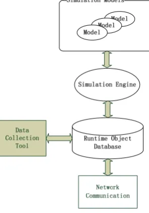
Runtime object database is a virtual database, which provides a unified method to represent simulation object data and
the transparent distributed communication capabilities. The database supports publish/subscribe facility. Simulation entities
publish their states to the database and subscribe the messages they interested in. Runtime object database supplies the
interoperation environment between simulation entities, and provides data access ports for simulation tools, such as
visualization tools and data collection tools. It hides network communication protocols from the simulation models and
simulation services above this database. The relationship between runtime object database and other modules is shown below.
International Journal of Engineering and Technology Innovation, vol. 2, no. 4, 2012, pp. 265-272 272
and the database which translate the model data into runtime object data model, and a layer between the database and the
network communication service which translate the runtime object data model to data structures of the specific network
communication protocol.
7.
Conclusion
This paper presents the architecture of a modeling and simulation environment, in which simulation components are
composed to construct the simulation application. This simulation environment provides common simulation services and
offers every chance to reuse exited resources to simplify development of complex simulation systems. By using of the runtime object database and software adapters including HLA-DEVS and DEVS-DIS agents, this environment can be compatible to
many distributed interoperation protocols, such as HLA, DIS et cetera. By composing simulation services, this simulation
environment can be tailored and specified to meet the needs of certain simulation applications.
Acknowledgements
This research was supported by grant 61104057 and 61074144 from the Natural Science Foundation of China and
Pre-research project of PLA. The authors thank the reviewers for their comments.
References
[1]IEEE Criteria for Distributed Simulation Engineering and Execution Process, IEEE Standard 562, 1982. [2]IEEE Criteria for Modeling and Simulation (M&S) High Level Architecture (HLA), IEEE Standard 1516, 1999. [3]IEEE Criteria for Distributed Interaction Simulation, IEEE Standard 1278, 1995.
[4]U.S. Department of Defense, “The Test and Training Enabling Architecture Reference Document,” 12th IEEE/ACM International Symposium on Distributed Simulation and Real-Time Applications, Nov 2002, pp.259-268.
[5]The Common Object Request Broker: Architecture and Specification, Victorian Electronic Records Strategy, 2nd ed., 2003. [6]Bernard P. Zeigler, Herbert Praehofer, Tag Gon Kim, Theory of modeling and simulation, Academic Press, 2000.
[7]Brett Butler, “Simulation Composability for JSIMS,” Proc. Distributed Interactive Simulation and Real-Time Applications, 2nd International Workshop,1998 , pp. 4-14
[8]Robinson, S., “Choosing the Right Model: Conceptual Modeling for Simulation,” Proceedings of the Winter Simulation Conference, 2011.
[9]Robinson, S., “Conceptual Modeling for Simulation Part I: Definition and Requirements,” Journal of the Operational Research Society, vol. 3, pp. 278-290, Jan 2008.
[10] Robinson, S., “Conceptual modeling for simulation part II: a framework for conceptual modeling,” Journal of the Operational Research Society, vol. 3, pp. 291-304, Oct 2008.
[11] Gabriel A. Wainer, Discrete-Event Modeling and Simulation: A Practitioner's Approach [M]. UK: Taylor and Francis Press, 2009.
[12] Qi Liu, Gabriel Wainer, Parallel Environment for DEVS and Cell-DEVS Models, SIMULATION, Vol. 83, Issue 6, June 2007, 449–471.
[13] Jeffrey S. Steinman, Craig N. Lammers, Maria E. Valinski, Maria E. Valinski. Simulating Parallel Overlapping Universes in the Fifth Dimension with HyperWarpSpeed Implemented in the WarpIV Kernel, 08S-SIW-025, 2008.
[14] Craig Lammers, Jeffrey Steinman, Maria Valinski1, Karen Roth, Five-Dimensional Simulation for Advanced Decision Making, SPIE – Enabling Technologies for Simulation Science XIII, Paper SPIE 7348-16, 2008.
[15] S.Y. Wang, C.L. Chou, C.C. Lin, “The design and implementation of the NCTUns network simulation engine,” Simulation Modelling Practice and Theory, vol. 15, pp. 57-81, May 2007.
[16] Olivier Labarthe, Bernard Espinasse, Alain Ferrarini, Benoit Montreuil, “Toward a methodological framework for