Copyright © The Author(s). 2014. All Rights Reserved. Published by American Research Institute for Policy Development DOI: 10.15640/jea.v2n2a2 URL: http://dx.doi.org/10.15640/jea.v2n2a2
Formulation of Problem-Based Learning in “Building Components Design”
Education
Semih G. Yildirim1, Stuart W. Baur2 & Roger A. LaBoube3
Abstract
“Building components design” education is carried out in different names in undergraduate education. The educational model presented herein accepts the building as a set of systems. Used notions of prefabrication, open building concept and prescriptive codes are the determiner for problem-based learning in “building components design” education. Problem-based learning as an alternative to traditional lecture learning environment targets students’ retention of desired knowledge. Results from this ongoing research with are discussed in this paper. The aim of this research is to show that PBL is an applicable educational model in “building components design” by using specific methodology. Therefore a series of methodologies and applicable building technologies are being presented herein. Existing notions in building industry are being applied to higher education by defining a formulation. The task in desired learning environment is to complete scaled models of selected building technology. The selection depends on the available and workable material for the students. This formulation is being tested already and proposed herein for other related courses as long as doing necessary revisions.
Keywords: Problem-based learning, building components design, open building
Introduction
Timber and cold-formed steel framing systems are widespread in construction industry in the world as both stick-built and panelized systems. In addition, reinforced concrete (RC) prefabricated, autoclaved aerated concrete (AAC) panel and structural insulated panel (SIP) systems are the other possible construction methods for panelized system used widely as well. Engineers, architects and other building professionals need basic knowledge of these construction methods. Meeting needs of future engineers and architects, education of construction methods is an essential part of the undergraduate curriculum of architectural engineering. Problem-based learning is incorporated with the thought learning environment to teach “building components design” in higher education beside traditional learning environment. Particularly hands-on learning experience is crucial to improve design skills and longer retention of desired knowledge. Design education of industrialized building systems have been carried out in architectural and civil engineering departments in different names in the world.
1 Ph.D, Visiting Scholar, Missouri S&T, CArEE Department, (Corresponding author) 211 Butler-Carlton Hall, 1401 N. Pine St.
Rolla, Missouri, phone; 573 341 4461,Email; [email protected]
2 Ph.D, Assoc. Prof., Missouri S&T, CArEE Department
Possible course titles are; “industrialized building systems’ design”, “building systems design”, building components design”, “architectural materials and methods of building construction” or separate courses related with reinforced concrete building system, timber and cold formed steel framing systems, etc.
As a research field, description of “industrialized building system” is more common in the literature, but as a course description herein “building components design” covers above mentioned possible course names in higher education. Problem-based learning (PBL) is an alternative to traditional lecture learning environment and helps to bridge gap between academia and practice (Smith, 2005). PBL asks for an active learning attitude and students are in a constructive investigation (Dochy, 2005; Yousuf, 2010). PBL can be described as a learning environment where the problem drives learning (Klegeris, 2011) or as “learning by doing”. Three fundamental types of project work can be distinguished in PBL; the task project, the discipline project and the problem project (Graaff, 2003; Yildirim, 2014a). The scope has been selected as “the task project” for “building components design” course and part of the results are discussed separately (Yildirim, 2012a; 2012b ; 2014a; 2014b).The difference of this paper than early studies and so, the hypothesis of this paper is; PBL is an applicable educational model in “building components design” by using specific methodology. The aim of this paper is to present a methodology and applicable building technologies to meet the desired learning outcomes. Hands-on learning experience was used in “building components design” course (Yildirim, 2012a; 2012b) and later improved in “architectural materials and methods of building construction” course by using PBL approach (Yildirim, 2014a; 2014b). Spacing of 12”, 16” or multiplier between structural members are common ground for the building technologies presented herein either it can be stick-built or panelized systems. Therefore, the common convention on modular grid specifies five different building technologies. Completion of scaled model of selected building technology is “the task project” in PBL environment.
1. Methodology Used in Building “Components Design” Education
Prefabrication rules and open building concepts are commonly known in construction industry and/or studied in scholar level. The difference of this paper is; using and combining existing notions in higher education. The methodology in “the task project” consists of three crucial aspects. These are prefabrication rules, open building concept and prescriptive methods and presented to the students in a design guide. These notions are the basis for creating a design guide for PBL environment;
The modular coordination in prefabrication rules maintains designer and manufacturer ease of coordination
between building components. Before introduction of open building concept, the focus was very much on “modulation” and “prefabrication” (Troyer, 2014).
Open building concept increases design diversity in prefabrication which was introduced in 1960’s by John
Habraken. Decision making process is distinguished in levels as “support (base building) level” and “in-fill (fit-out) level” and particularly “dimensional coordination” is focused (Habraken, 1961). Common conventions are required to implement open building concept in building industrialization to use limited number of members by dimensional coordination (Cuperus, 2001). Common conventions refer user / design guide as it is in toy and furniture industry such as; meccano, lego, ikea, etc.
Prescriptive codes (Mehta, 2008) are used in “building components design” education. The use of prescriptive
codes and how they impact the design of construction system in addition to hands-on learning help the students to better understand design principles of stick-built and panelized construction systems. Design limitations of PBL activity can be described as within the limits of prescriptive codes such as; it is possible to cross longer span for floor joists than accepted dimensions according to prescriptive codes.
Table 1.Formulation of PBL in Building Components Design (Yildirim, 2014b)
Transferring of experiences of furniture and toy industries to building industry takes an important role in industrialization of building. Meccano is a model construction system comprising re-usable components and it enables the building of working models and mechanical devices in toy industry (Url 1, 2012). It was invented in 1901 in England and the principles and the name was used in industrialization of building in 1960’s. Similarly, re-usable components are used in Lego Architecture and installation with defined components is done by customer in Ikea furniture concept as shown in Figure 1. User manuals help to installation of these systems. Customers can select their furniture in IKEA outlets and put them together all by themself.
Figure 1. Meccano, Lego Architecture and Ikea Furniture Concept (a) (Url 1, 2012), (b) (Url 2, 2012) and (c) (Url 3, 2012)
1.1 Prefabrication Rules
Industrialization in construction is required due to technical and economic reasons as being in toy and furniture industry.
The existing strategies for industrialization in construction can be divided in two categories, each with its own typical approach as on-site and off-site industrialization. On-site industrialization refers to the application of advanced tools and technologies on building sites. Most on-site industrialization is possible without design changes. Off-site industrialization is based on the assumption that buildings may also be made in factories. Another split in industrialization strategies may be: product industrialization and process
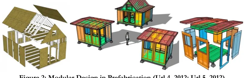
industrialization (CIB, 2014). Standardization and distinguishing of building to sub systems is the basic
notion of building industrialization as shown in Figure 2.
c b
Figure 2: Modular Design in Prefabrication (Url 4, 2012; Url 5, 2012)
The concepts “closed building systems” and “open building systems” are widely used in the context of industrialisation of the construction sector. The term “closed building system” is used to describe the approach of the building sector after the World War II in Europe. The term “closed” was added in the sixties and has a negative connotation.The term “open system building” is a neologism for an alternative approach for those “closed building systems”. In all cases a lot of components are bought on the market. Therefore one should take care that certain dimensions of the self-produced building parts fit with these
other components. Disadvantages of “closed building systems” approach are (Troyer, 2014);
only a limited choice between a few types of houses for each project (otherwise production series are to
small)
monotony of large sites
monopolistic positions for producers and large scale contractors.
1.2 Open Building Concept
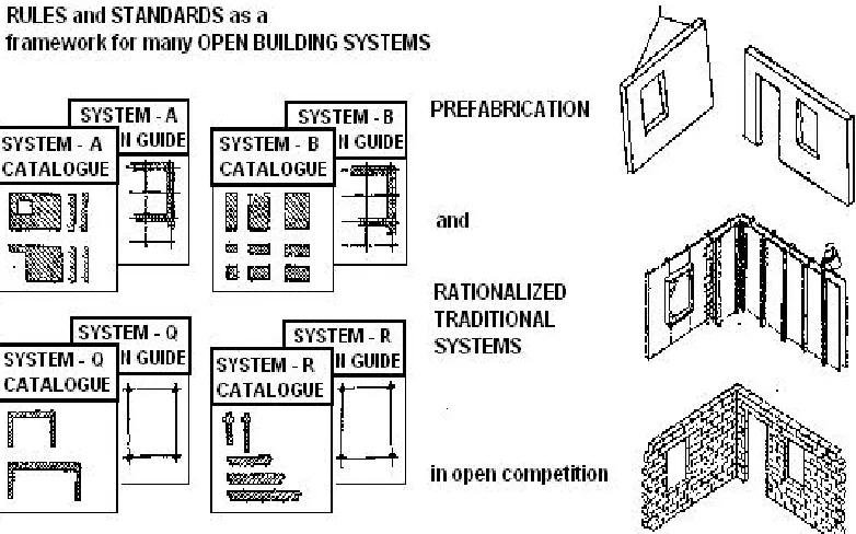
The term “open building system” (Figure 3) is used when the starting point is totally different. In the case of “open building system” one also starts from a specific project, but by respecting a certain dimensional discipline the elements produced for that project will fit with components of many independent manufacturers. One does not start from a specific project but one develops a set of elements which can be combined in many ways. So the term of “open building system” can be used when the two following conditions are fulfilled (Troyer, 2014);
With limited number of elements which are part of the system, an unlimited number of different projects
can be realised. There will however always be a set of constraints for the design of those projects. The “design guide” will inform the designer of the rules he has to follow (grids, positioning-rules, and requirements for stability).
The building elements of that “open building system” are co-ordinated with components of different
(beforehand unknown) producers.
Open building concept can be implemented over any kind of building technology and dimensional coordination is prerequisite for this concept. The role of designer in “open building” concept is; designing by using common conventions with limited number of components independently from the manufacturer (Atasoy, 1995). Dimensions and positions of the components are determinative while consisting of
geometrical shape of the building during design phase (Şener, 1990). “Open building” implementation
Figure 3: Open Industrialization (Troyer, 2014)
Levels of Decision Making
Re- distribution of design control is the field of industrial systematization. Design, production and installation processes are distinguished between designers and manufacturers by common conventions in “open building” concept. Building systems are separated as support (base building) and infill (fit-out) level in Figure 4 and “support” refers to structural system and envelope of a building and “infill” refers to partitioning walls, kitchen systems, utility systems and etc. These systems are designed separately from each
other in “open building” concept (Habraken, 2005).The scope of support (base building) and infill (fit-out)
levels are shown in Table 2.
(a) Support (Base Building) (b) Infill (Fit-out)
Figure 4. Distinguishing of Levels in “Open Building” Concept (Kendall, 2002) the fit-out concerns what is decided by each tenant
independently the base building
Table 2: The Scope of Support (Base Building) and Infill (fit-out) Level (Url 6, 2012)
Modular Coordination
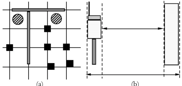
Rules for dimensions, position and interfaces of building parts are a prerequisite for “open building”. Based on Habraken's book 'Support, an alternative to mass housing' (Habraken, 1961), later the SAR (foundation for Architectural Research) published SAR '65. Based on the basic module of 4 feet, a 'tartan-grid' was developed (Cuperus, 2005). Later on SAR, research groups as OBOM and CIB workgroup W104 were formed. To use a grid as a design tool, the designer must determine rules for placing elements relative to the grid. The simplest and most obvious placement rule is that elements center on grid crossings. Figure 5a shows different position relations for elements on a simple square grid. Grids need not be always unitary; an alternating sequence of dimensional units can be used, to form a tartan or band grid (Figure 5). A tartan grid can be superimposed on a simpler grid that marks the band centerlines.
Elements can be restricted to center on the centerline grid, and limited in dimension to stay within the tartan bands (Gross, 2012).
(a) (b)
(a) (b)
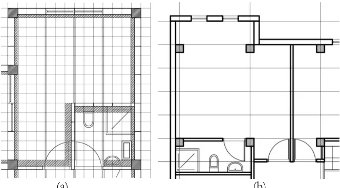
Figure 6: (a) Position of Building Elements on Grid of ACC Building System, (b) Position of
Building Elements on Grid of Solfege Building System (Yildirim, 2000)
In the 1970’s, Finnish industry developed an open element system called the BES system. The initial wall-slab system was used for housing, then frame-slab system was developed for industrial, commercial and institutional buildings (Url 7, 2012).
Similarly, ACC and Solfege Building Systems were developed in France in “open building” concept as defining of common conventions and modular coordination of building elements on choiced grid. 12x12 inch (~30x30 cm) tartan grid in ACC system and 3x9 feet (~90x270 cm) simple grid in Solfege system were used and defined positions of building elements on grids are shown in Figure 6. Variety grid and positioning of building elements can be defined, but the more practical rules are the better in terms of solving interface problems.
1.3 Building Codes (Performance codes & Prescriptive codes)
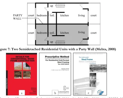
In a performance code, the performance criteria of a component are specified instead of the material or the construction system. The performance criteria are based on the function of the component. For example, a prescriptive code might require an 8-in.-thick brick wall as a party wall between two semidetached residential units in Figure 7. It might further specify the type of bricks and the type of mortar to be used in joints. A performance code, on the other hand, states the required properties of the wall, such
as the fire resistance, sound insulation, load-carrying capacity, and durability characteristics (Mehta, 2008).In
Figure 7: Two Semidetached Residential Units with a Party Wall (Mehta, 2008)
Figure 8. Samples of Prescriptive Codes (a) (AWC, 2001), (b) (NASFA, 2000), (c) (CSSBI, 2005)
2. Applicable Building Technologies
Material and methods of construction are variable in building technologies, such as; a) galvanized profiles, dimensional lumber, reinforced concrete, aerated concrete or OSB panels with insulation layer are commonly in use as material and, b) stick-built system and panelized system are in use in terms of construction method. While considering low rise residential (1 to 3 story buildings) as a study field of which accepted in PBL activity, five different construction methods are being introduced herein. These are the building technologies studied already or having possible to be studied in further courses in conformity with this educational model;
a) Timber framing system
b) Cold-formed steel (CFS) framing system
c) Reinforced concrete (RC) prefabricated system
d) Autoclaved aerated concrete (AAC) panel system
e) Structural insulated panel (SIP) system
Having a common ground as spacing possibility with 12”, 16” or multiplier at each system is the selection reason of these systems. The systems from (a) to (d) have already been studied as a hands-on learning experience in related courses, (e) is being proposedas well which has possibility to be studied in PBL environment. Each system is being introduced briefly in this section. Before starting to hands on learning experience by selecting of any of system herein, prior knowledge shall be maintained to the students at the lecture sessions. Selection of structural system for scaled model study in a course is directly dependent on to availability and workability of the scaled model members.
In order to fulfill “the task project” in PBL environment by completing a scaled model, students need further information, such as; design guide. But, the design guide used in this PBL environment is out of scope of this paper and discussed separately.
a) Timber Framing System
Wood material is being used as a structural member in housing construction widely in the world and classified in two types as log houses and wood light frame construction. The latter is also called as timber framing system. Timber framing system consists of by the usage of dimensional lumber and engineered wood products such as plywood and OSB (oriented strand board). Consistent material supply, ease of workability, having competitive price of these materials in the market makes timber framing system still popular. On the other hand, due to its conformity with the prefabrication rules as stick-built system or panelized system brings advantage during selection of structural system of a residential.
In terms of construction method, there are two methods in wood light frame construction; balloon frame and platform frame system. Wood light frame system was invented to replace the heavy construction
systems in 19th century in USA, such as; thick masonry wall, heavy timber posts, beams and thick wood
plank floor and roofs. First, balloon frame was introduced then, platform frame invented to maintain a platform at each level of the construction. In the platform frame, the subfloor at the first floor level is completed soon after laying the floor joists at that level (Figure 9). This subfloor provides a platform for the workers to stand on and to build the following story (Mehta, 2008; Götz, 1989; Chiuini, 2007).
Figure 9. Timber Framing System (a) (Url 8, 2012), (b) and (c) Photograph by Semih G. Yildirim, Kumburgaz, Istanbul
b) Cold Formed Steel (CFS) Framing System
Steel structures are constituted by two ways. The skeleton of a building as columns and beams
erected by hot rolled steel profiles as I, U and box sectional profiles in the first alternative. The second way is walls and floors are installed by using thin structural steel members as galvanized cold formed steel profiles. Latter is called as CFS framing system (Figure 10) (Smith, 1996).
Figure 10: CFS Framing System (Photograph by Semih G. Yildirim,Bahcesehir, Istanbul)
a b c
Installation principle, placement of wall studs and floor joists, connection properties, load distribution of CFS framing system is similar with timber frame system. The main difference of this system is; usage of hollow core galvanized steel profiles having high conductive value instead of usage of solid
timber section having high insulation value (Işık, 2001).Wall and floor are formed in CFS framing system
with many types of structural members in an order as being in timber frame system. In addition to horizontal or diagonal bracing, walls and floors are supported by structural sheeting particularly used OSB. U, C and other galvanized steel profiles as steel structural members shape CFS framing system and maximum story of building is variable as two or three in different specifications published in variety countries in the world, but the limitation is accepted as three story building is possible to erect. Construction of a building with light frame members is called as “stick construction”. “Stick construction” is distinguished as “balloon frame system” and “platform frame system” due to connection type of load bearing members at the wall and floor (Ang, 2004).
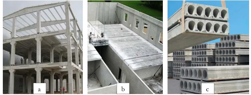
c) Reinforced Concrete (RC) Prefabricated System
RC prefabricated building system for residentials are classified as stick (frame) system, panelized system and volumetric (box) system. Not only industrialization level increases through volumetric system, but also need of mass production increases. When compared the mentioned sub-systems, stick system gives more design flexibility than the others. Moreover, it has ease of manufacturing properties, transportation and lifting of the manufactured members despite of increasing workmanship on-site. On the other hand, type of modular members as column, beam and floor panel can be decreased and design diversity can be increased at the same time (Figure11) (Ayaydin, 2004). Therefore, stick-built system with column and beam is being focused in this case study of proposed educational model. Wall and floor are being considered as panelized members.
Figure 11: RC Prefabricated System, (a) (Url 9, 2012), (b) (Url 10, 2014), (c) (Url 11, 2014)
d) Autoclaved Aerated Concrete (AAC) Panel System
AAC (otherwise known as Aerated Cellular Concrete or Aircrete) was developed by a Swedish architect, and was patented in 1920’s. AAC products include blocks, wall panels, floor and roof panels, cladding (facade) panels and lintels (Url 12, 2014).
Figure 12: AAC Panel System, (a and b) (Ytong, 2007), (c) (Url 13, 2014)
AAC offers significant advantages over other cement construction materials; being lightweight material results in less dead load of the structure, improved thermal efficiency reduces the heating and cooling load in buildings; porous structure allows for superior fire resistance, being sound absorber eliminates usage of other sound insulation layers and smooth surface minimizes finishing and plastering cost during construction process (Boggelen, 2014). Steel reinforcement is also used in AAC panels (Boggelen, 2011) and it is called reinforced AAC elements as load bearing wall panels, floor and roof panels and included in this educational model (Figure 12).
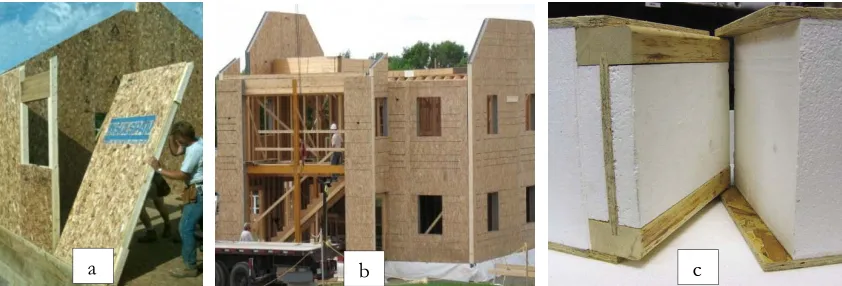
e) Structural Insulated Panel (SIP) System
SIP system is a panelized system that reduces on-site construction time and allows the use of less-skilled labor. The SIP system consists of sandwich composition. Each panel comprises two facing boards bonded to a core consisting of rigid plastic foam insulation (Figure 13). The core generally consists of expanded polystyrene (EPS). OSB is commonly used for the facings (Mehta, 2008). SIPs enable structures to be assembled with minimal framing up to two story building above basement. The framing factor is a measure of thermal bridging. The more framing, the higher the framing factor and the more energy are lost due to thermal bridging. There are two options for floor systems when constructing a home with SIPs. First is hanging floor system, that floor joists are attached to the side of wall panel using metal hangers, the second one is a typical platform floor design (Url 14, 2007).
Figure 13: Structural InsulatedPanel System, (a) (Url 15, 2014), (b) (Url 16, 2014), (c) (Url 17, 2014)
3. Conclusion
Earlier studies of this research shows that the necessity of hands-on learning experience in architectural engineering programs and positive impact of PBL over traditional lecture learning environment.
a b c
On the other hand, course curriculum design is highly promoted by using variety modules. This paper shows that PBL in “building components design” education is applicable by using specific methodology. This methodology is formulated by combining three notions as; prefabrication rules, open building concept and prescriptive codes. These are the existing notions in building industrialization and being implemented in higher education. Open building can be applied on any kind of building technology. The common ground for the building technologies is modular coordination. Spacing with 12”, 16” or multiplier are commonly used in framing system, beside applicable for panelized system as well. Due to accepted modular dimension, five building technologies have been selected which can be studied in “building components design” education. Scaled model activity of these building technologies is the task for the PBL environment. Available and workable material for a scaled model study is the determiner of selection of building technology. Timber and cold-formed galvanized steel profiles are being used in framing construction and can be erected in both ways as stick-built and panelized systems. R.C. prefabricated system presented herein is accepted as a stick frame columns and beams, panelized wall and floors. AAC panel system and SIP system can be directly assembled as panelized systems. The proposed educational methodology has been used in architectural engineering program and the design guide and learning outcomes are being discussed separately. This is an ongoing research to improve this educational methodology and any kind of alteration can be done due to need of related course curriculum.
Bibliography
Ang, T. C., Chiew, S. P., Lam, D., (2004). Structural steelwork; design to limit state theory. Elsevier Butterworth-Heinemann, Oxford
Atasoy, A., Şener, H., Şener, S. M., Pulat, G., Erem, O., (1995). Türkiye’ de toplu konut üretiminde kullanılabilecek ulusal nitelikli bir endüstrileşmiş sistem tasarımı araştırma projesi, 1. aşama: envanter. İ.T.Ü. Araştırma Fonu,
İstanbul.
AWC, (2001). Details for conventional wood frame construction.American Forest & Paper Association (AWC), Washington. [Online] Available: http://www.awc.org/ pdf/wcd1-300.pdf.
Ayaydın Y., Koman, İ., (2004). 12 soruda beton prefabrikasyon. Yapı Endüstri Merkezi, Istanbul.
Boggelen, W. V.,(2011). The contribution of AAC in securing a sustainable future. 5th International Conference on Autoclaved Aerated Concrete, Bydgoszcz, ISBN 978-83-89334-26-4.
Boggelen, W. V.,(2014). Fast and green construction with autoclaved aerated concrete prefab productsNew ways of AAC application – AIRCRETE Building System. [Online] Available: http://www.aircrete-europe.com/ downloads.html.(Sept. 07, 2014)
Chiuini, M., Underwood, R., (2007). Structural design, a practical guide for architects.John Wiley & Sons Inc. New Jersey, USA.
CIB, (2004). Industrialisation in construction. International Council for Research and Innovation in Building and Construction.[Online] Available: http://cibworld.nl.(Sept. 09, 2004)
CSSBI, (2005). The lightweight steel frame house construction handbook. Canadian Sheet Steel Building Institute (CSSBI), Canada. [Online] Available: http://consteel.com.br/docs/CSSBI/CSSBI%20%20The%20Light weight%20Steel%20Frame%20House%20Construction%20Handbook%20-%200%20%20Introduction. pdf (January 15, 2010)
Cuperus, Y., (2001). An introduction to open building, OBOM open building strategic studies, Delft University of Technology, Netherland. [Online] Available: http://cic.vtt.fi/lean/singapore/cuperusfinal.pdf.
Cuperus, Y., (2005). An introduction to open building, OBOM open building strategic studies. Delft University of Technology, Netherland. [Online] Available: http:// obom. org. (March 22, 2005)
Dochy, F., Segers, M., Bossche, P. V. D., Struyven, K., (2005). Students’ perceptions of a problem-based learning environment. Learning Environments Research (2005) 8: (pp. 41–66), Springer. [Online] Available:
http://www.researchgate.net/publication/226219806_Students_Perceptions_of_a_Problem-BasedLearningEnvironment/file/ 79e415139a443b766a.pdf
Graaff, E. D., AnetteKolmos, (2003). Characteristics of problem-based learning. Int. J. Engng Ed. Vol. 19, No. 5, pp. 657-662, 2003, printed in Great Britain, Tempus publications. [Online] Available: http://www.ijee.ie /articles/ Vol19-5 /IJEE1450.pdf
asro.kuleuven.ac.be/asro/English/HOME/Fdt/FrankDeTroyer_files/systembuilding/Industr%20build%20. htm. (June 05, 2014)
Gross, M. D., Grids in design and cad, University of Colorado. [Online] Available: http://code.arc.cmu.edu/ archive/dmgftp/public_html/publications/pdfs/acadia91 mdg.pdf. (Jan. 10, 2012)
Habraken, N. J., (1961). Supports, an alternative to mass housing. London 1972, Amsterdam 1961 (Dutch version) Habraken, N. J., (2005). Open building as a condition for industrial construction. [Online] Available: http://
habraken.org. (March 21, 2005)
Işık, B., 2001. Hafif çelik yapıların geleneksel ahşap yapılar ile benzerlikleri. Türk Yapısal Çelik Derneği, [Online] Available: http://tucsa.org> dated (July 15, 2001)
Kendall, S., (2002). An open building industry: making agile buildings that achive performance for clients. 10th International Symposium Construction Innovation & Global Competitiveness, Cincinnati, Ohio, USA
Klegeris, A., Hurren, H., (2011).Impact ofproblem-based learning in a large classroom setting: methodology, student perception and problem-solving skills. AdvPhysiolEduc 35: (pp. 408–415) 2011, Canada. [Online] Available: doi:10.1152/ advan.00046.2011. 408 1043
Mehta, M., Scarborough, W., Ampriest, D., (2008). Building construction; principles, materials, and systems. Pearson Prentice Hall, USA
NASFA, (2000). Prescriptive method for residential cold formed steel framing. North American Steel Framing Alliance (NASFA). [Online] Available: http://steelframingalliance.com. (April 12, 2002)
Smith, K. H., (2005). Problem-based learning in architecture and medicine: comparing pedagogical model in beginning professional education. 21st National Conference on the Beginning Design Student, University of Texas at
San Antonio, 24-26 February, 2005. [Online] Available: http://www.novicedesign.org/NCBDS/21/pdf/22_ The Beginners Mind.pdf.
Smith, R. J., (1996). Innovations in steel, residential construction around the world. International Iron and Steel Institute, Belgium
Şener, H., (1990). Endüstrileşmiş binada açık sistemler (Open systems in industrialized building). Publication of ITU Faculty of Architecture, Istanbul.
Troyer, F. D. “System building” or “Industrialised building”: A review of approaches and a vision for the future. [Online] Available: http://www.asro.kuleuven.ac.be/asro
/English/HOME/Fdt/FrankDeTroyer_files/systembuilding/Industr%20build%20.htm. (Sept. 05, 2014) Url 1. [Online] Available: http://en.m.wikipedia.org/wiki/Meccano. (Jan. 10, 2012)
Url 2. [Online] Available: http://architecture.lego.com/en-us/products/landmark/rockefeller- center. (Jan. 10, 2012)
Url 3. [Online] Available: http://www.ikea.com/us/en/catalog/categories/series /09064. (Jan. 10, 2012) Url 4. [Online] Available: http://www.tinyhousedesign.com/2011/09/22/prefab-hybrid. (Jan. 10, 2012)
Url 5. [Online] Available: http://www.tinyhousedesign.com/wp-content/uploads/2009/09/ panel-system.jpg. (Jan. 10, 2012)
Url 6. Open building. [Online] Available: http://en.wikipedia.org/wiki/openbuilding. (March 01, 2012)
Url 7. The Finnish experience on industrialisation. [Online] Available: http://www.bca.gov.sg/publications/ buildabilityseries/others/rscp_anxa.pdf. (Jan. 10, 2012)
Url 8. Timber frame house. [Online] Available: http://3.bp.blogspot.com/-2EckWJoZj3Y/TusfOSwMg-I/AA AAAA AAA9E/hFnIvMJycjo/s1600/timber+house.jpg. (Jan. 10, 2012)
Url 9. Reinforced concrete prefabricated system. [Online] Available: http://www.cevre.com/resimler /AEE_ betonarme.jpg. (Jan. 10, 2012)
Url 10. Reinforced concrete wall and floor panels. [Online] Available: http://www.cpci.ca/en/about_ us/project_ month/october_2005/. (Sept. 02, 2014)
Url 12. [Online] Available: http://www.aircrete-europe.com/aircrete-aac/what-is-autoclavedaerated-concrete. html. (Sept. 07, 2014)
Url 13. Aerated concrete panel system. [Online] Available: http://www.yapikatalogu.com/Vimages/Firmalar/1219/ FotografDosyalari/b_26446_prefabrike-konutlar.jpg. (Sept. 02, 2014)
Url 14. Structural insulated panels, product guide, (2007). Structural Insulated Panel Association (SIPA) and The Engineered Wood Association (APA). [Online] Available: http://www.tolko.com/documents/APA_H650 _Product_Guide_Structural_ Insulated_Panels.pdf
Url 15. [Online] Available: http://buildipedia.com/images/masterformat/Channels/On_Site/SIPs/panel_install_3. jpg. (Sept. 07, 2014)
Url 16. [Online] Available: http://terrahaus.files.wordpress.com/2011/06/6-20-2011-002.jpg. (Sept. 07, 2014) Url 17. [Online] Available: http://www.northshorehwy61.com/bm/bm~pix/typical_roof_panel_con_opt~s600x6
00. jpeg. (Sept. 07, 2014)
Yildirim, S. G., (2000). Term project for MSc course in ITU (unpublished). Advisor; Prof. Dr. Hasan Sener
Yildirim, S. G. (2012a). Design education of industrialized building systems. The World Conference on Design, Arts and Education, May 1-3 2012, Antalya, Turkey. Elsevier, Procedia - Social and Behavioral Sciences, Volume 51, 2012, (pp. 84–89). [Online] Available: http://dx.doi.org/10.1016/ j.sbspro.2012.08.123
Yildirim, S. G. (2012b). Definition of common conventions for education of CFS system design.21st international specialty conference on cold formed structures, October 23-24, 2012, St. Louis, Missouri.Wei-Wen Yu Center for Cold Formed Steel Structures, Missouri S&T.
Yildirim, S. G., Baur, S. W., LaBoube, R. A., (2014a). Problem-based learning with framing construction in architectural engineering, Journal of Engineering and Architecture, Vol. 2, No. 2, pp. 63-74, Dec., 2014. Published by American Research Institute for Policy Development, NY.
Yildirim, S. G., Baur, S. W., LaBoube, R. A., (2014b). Fundamentals of framing construction in architectural engineering; a hands-on learning experience. 2014 Midwest Section Conference of the American Society for Engineering Education, Sept. 24-26, 2014, University of Arkansas, Fort Smith, AR, USA. [Online] Available: http://www.uafs.edu/sites/default/files/users/yildirim.pdf
Yousuf, A., Mustafa, M., Cruz, A. D. L., (2010). Project-based learning (PBL). American Society for Engineering Education Annual Conference and Exposition, Louisville, Kentuky, 20-23 June 2010. [Online] Available: http://heeap.org/sites/default/files/Introduction%20to%20Problem%20Based%20Learning%20%20ASEE %20Paper. pdf