Experimental and CFD Study of the Tube Configuration Effect
on the Shell-Side Thermal Performance in a Shell
and Helically Coiled Tube Heat Exchanger
R. Beigzadeh, A. Parvareh*, M. Rahimi
CFD Research Centre, Department of Chemical Engineering, Razi University, Kermanshah, Iran
Abstract
Despite numerous studies of shell and helically coiled tube heat exchangers, a few investigations on the heat transfer and flow characteristic consider the geometrical effects like coil pitch. Moreover, this scarcity is highlighted for the shell side of this type of heat exchangers. This study reports experimental and Computational Fluid Dynamics (CFD) investigations on heat transfer and flow characteristics of a shell and helically coiled tube heat exchanger. The experiments were carried out using a helically coiled tube, which was placed in a cylindrical shell. Hot and cold water were used as the process fluids on the tube and shell side, respectively. The CFD modeling technique was employed to describe the experimental results, fluid flow pattern, and temperature profiles as well as dead zones in the heat exchanger. Quantitative predicted results of CFD modeling show a good agreement with the experimental data for temperature. The effect of the coil pitch on heat transfer rate was numerically studied and it was found that the heat transfer coefficient intensifies with an increase in coil pitch. The average turbulent kinetic energy (k) for the old coil tube and twice coil pitch heat exchanger was computed as 2.9×10⁻³ and 3.3×10⁻³ m2/s2, respectively. This indicates an increase of about 14% in flow turbulent kinetic energy. Nusselt numbers were compared with those estimated using published correlation and a mean relative error (MRE) of 14.5% was found between the experimental and predicted data. However, a good agreement was obtained in lower shell Reynolds numbers (lower than Re=200).
Keywords: Heat Exchanger, Helically Coiled; Shell Side, Computational Fluid Dynamics (CFD), Modeling
1. Introduction
Heat exchangers with helically coiled tubes have been employed in many industrial applications such as power plants, process plants, refrigeration process and heat recovery systems [1-5]. High heat transfer coefficient and the compact structure of these heat exchangers are the main reasons for these applications [5,6]. In helically coiled tubes, the centrifugal force generated by the
Corresponding author: arsalanparvareh@yahoo.com
curvature of the tube leads to a secondary flow which causes a higher heat transfer coefficient. However, in this type of heat exchanger a higher pressure drop is observed compared with those of straight tubes.
two-phase flows in curved tubes were presented. Numerical modeling of the flow and thermal characteristics of nanofluids in curved tubes was done by Ebrahimnia-Bajestan and Niazmand [7]. They used control volume technique to solve incompressible Navier-Stokes and energy equations. The results show that the heat transfer rate was increased. Moreover, employing the nanoparticles leads to more uniform cross sectional temperature distributions. Beigzadeh et al. [8] investigated the effects of curvature ratio and torsion of the coiled tubes on thermal and flow characteristics. They applied a genetic algorithm-based multi-objective optimization method to obtain optimal geometric parameters for the coiled tubes which leads to a trade-off between Nusselt number (Nu) and friction factor (f). Moreover, the Artificial Neural Network (ANN) and Adaptive Neuro-Fuzzy Inference System (ANFIS) modeling were done to predict the heat transfer and flow characteristics in helically coiled tubes by Beigzadeh and Rahimi [9,10].
Shell and helically coiled tube heat exchanger is one of the wide uses of coiled tubes in heat transfer process. Salimpour [11] experimentally investigated the heat transfer rate of shell and helically coiled tube heat exchangers with different coil pitches for parallel-flow and counter-flow configur-ations. Also, empirical correlations were reported for prediction of Nu in tube side and shell side of the heat exchanger. In another work, Salimpour [12] studied heat transfer characteristics of temperature dependent-property engine-oil in shell and helically coiled tube heat exchangers. In his work, a
correction factor was applied to consider the effect of variable properties such as specific heat capacity and viscosity of the fluid in the empirical correlation for the prediction of Nu number.
Various types of shell and tube heat exchangers have been investigated in literature experimentally and numerically [13-16]. On the other hand, modeling of
hydrodynamics and heat transfer
characteristics of coiled tubes have been considered in other literature [17-20]. CFD modeling has been performed in various publications [19,20] and the effect of dimensionless geometrical parameters of helically coiled tubes such as curvature ratio and coil pitch on heat transfer and flow characteristics have been investigated. CFD analysis inside helically coiled tubes for single-phase flows was done by Jayakumara et al. [20]. In their study, a correlation was developed to estimate the local Nu as a function of the angular location of a point.
effects of geometrical parameters such as coiled tube pitch on hydrodynamics and heat transfer rate were investigated.
2. Experimental work
A schematic diagram of the experimental setup is shown in Fig. 1. The setup consists of a single-phase heat exchanging system in which hot water passes through the helically coiled tube and exchanges heat with cold water flows inside the shellside.
The heat exchanger includes an insulated cylindrical shell which is equipped with a copper helically coiled tube. Characteristics of the heat exchanger have been presented in Table 1.
In the experiments, the hot water fluid was supplied from a storage tank equipped with an electric heater. The hot fluid was circulated from the tank through the coiled tube by a pump at a temperature in the range of 43.6 to 45.5°C. Mass flow rate of each stream was measured using two flowmeters. Both the parallel-flow and counter-flow configurations for the shell and coiled tube heat exchanger were investigated and
compared frequently with the literature [11,21]. In this study only a parallel-flow configuration was considered in the experiments. The pressure drop of each stream was measured using pressure transducers installed at the inlet and outlet of each side. In addition, the inlet and outlet temperatures were measured using 4 K-type thermocouples installed at the inlets and outlets.
Table 1
Characteristics of the heat exchanger.
Shell side Tube side
Process fluid Cold water Hot water Diameter (cm) 14.5 0.54
Length (cm) 34.5 300
Coil diameter (D) (cm) - 8.5 Coil pitch (H) (cm) - 3.2
Physical properties of each fluid have been evaluated at the inlet and outlet average temperatures. After beginning each run, it was allowed to reach a steady state condition and then data recording was performed.
3. CFD modeling
In this study, a three-dimensional numerical simulation of the turbulent flow and heat transfer developments is conducted by means of the CFD code FLUENT [22].
The solution domain consists of the cylindrical shell and helically coiled tube which was meshed using 906368 tetrahedral unstructured meshes. These mesh layouts were obtained through examination of different cell sizes as no further significant changes are revealed for finer meshes. Fig. 2 shows the actual coiled tube used in the experiments and the meshed configuration of the shell and coiled tube heat exchanger.
Figure 2. The meshed shell and coiled tube heat exchanger.
Some of the geometrical characteristics of the coiled tube, coil pitch (H) and coil diameter (D), are shown in the figure. Conservative equations of mass and momentum together with the energy equation were conducted for all of the cells in the
solution domain. The standard
turbulence model [23] with the standard wall functions was employed to simulate the turbulent flow regime and heat transfer development.
Segregated method is chosen as the solver type and the SIMPLE pressure–velocity
coupling algorithm, the standard pressure, the first order upwind discretization scheme for momentum, energy, turbulent kinetic energy and dissipation energy were applied in the model. Due to a reduction of the CPU time and no significant differences between the obtained results, the first order scheme was preferred over the more relevant second order one. Moreover, a convergence criterion of 10 8 was selected for energy and a value of 10 4 was employed for other calculated parameters.
4. Results and discussion 4-1. Experimental results
In order to investigate the heat transfer rate in the shell and helically coiled tube heat exchanger, the overall heat transfer coefficients were found using the following procedure.
The heat transfer rate from the hot fluid in the coiled tube and cold fluid in the shell side were calculated as follows:
) ( C m ) ( C m
Q t p,t ti to s p,s To Ti (1)
Where Q is the heat transfer rate, m is the mass flow rate, T is the shell side flow temperature, t is the tube side flow temperature, and Cp is the specific heat
%
Q
Q
Q
t ts
100
10
(2)This takes into account the heat transfer losses from the shell side of the heat exchanger to the surrounding air. The overall heat-transfer coefficient was obtained from the following equation:
LMTD o o T A Q U (3)
where Ao is the external surface area of
the coiled tube and TLMTD is the logarithmic
mean temperature difference, based on the inlet temperature difference ( T1) and the
outlet temperature difference ( T2) as
follows: 1 2 1 2 ln ) ( T T T T TLMTD (4)
Fig. 3 illustrates the variation of the obtained overall heat transfer coefficients for three flow rates of 3.1, 3.5 and 4.9 lit/min in the shell side at various tube side flow rates. As shown in this figure, an increase in flow rate either in the tube side or in the shell side enhances the overall heat transfer coefficient. The main reason for the enhancement of the overall heat transfer coefficient during the increasing flow rates is the increase of fluid flow turbulence intensity and consequently the increases of local convection heat transfer coefficient in both sides.
Shell side Reynolds number (ReS) and
Nusselt number (NuS), are defined as
Figure 3. Overall heat transfer coefficient for three shell side flow rates at various tube side flow rates.
D V
Re S h
S (5) f h S k D h Nu (6)
where kf is the thermal conductivity of the
fluid and VS, hS, and Dh are average velocity,
convective heat transfer coefficient, and the hydraulic diameter of the shell side, respectively. Fig. 4 illustrates the variation of the Nusselt number with Reynolds number for the shell side of the heat exchanger which was calculated based on hydraulic diameter of the shell. The NuS increased with
increasing ReS due to increase in convective
Figure 4. Nusselt number versus Reynolds number for shell side of the heat exchanger. (Points: Experimental data; Dashed line: Salimpour [11] correlation).
4-2. CFD modeling results
The measured outlet temperature of the helically coiled tube and shell are compared with those obtained from CFD modeling in Table 2. The mass flow rates and inlet temperatures in the CFD modeling were considered equal to corresponding experimental values and the outlet temperatures obtained from the experimental
measurements and CFD predictions have been compared. Acceptable differences between experimental and predicted data can be found that indicate the validity of the model.
The conditions of test number 1 in Table 2 were considered for the CFD analysis of the heat exchanger.
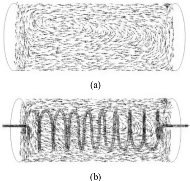
In the first step of the CFD modeling, the tangential velocity vectors in a vertical plane passing through the shell diameter are compared with those of a single shell without the coiled tube. As shown in Fig. 5, similar main flow patterns are dominated for both cases. The strength of the input stream pushes the fluid in the shell to the other side near the outlet and a small amount of the fluid goes out from the shell. However, most fluid returns to the inlet side. This causes a circulating flow in both cases, but the existence of the coiled tube led to further swirling flows near the coiled tube wall.
Table 2
The model validation for three data points.
Experimental Predicted
Test number 1 2 3 1 2 3
Tube side mº(kg/s) 0.1239 0.1238 0.1415 - - -
tin (K) 316.78 318.65 318.45 - - -
tout(K) 313.45 315.65 315.95 314.42 316.62 316.56
Shell side mº(kg/s) 0.0828 0.058 0.0526 - - -
Tin(K) 288.2 290.65 287.75 - - -
(a)
(b)
Figure 5. The tangential velocity vector in a vertical plane of the shell (a) without coiled tube and (b) with coiled tube and its grid.
A better understanding of the coiled tube’s effect on flow pattern in the shell can be obtained from turbulent intensity distribution. Fig. 6 (a, b) shows the turbulence intensity contour plots with and without the coiled tube in the above mentioned vertical plane of the shell. As can be seen in these figures, in both cases the turbulence intensity in the entrance part of the shell is stronger than in other parts due to higher velocity components in this region.
L=5 cm L=15cm L=25cm L=35cm
Figure 6. The turbulence intensity:
(a) In a vertical plane of the shell without the coiled tube. (b) In a vertical plane of the shell with the coiled tube. (c) In various slices along the shell length.
(for a better display limited to range of 0.18 – 7%). (a)
(b)
The existence of the coiled tube reduces the turbulence intensity due to reduction of the input stream strength. Trapping of fluid parts inside the coiled tube causes formation of dead zones that can clearly be seen in Fig. 6 (c). The turbulence intensity for various vertical slices along the heat exchanger length at distances of 0.05, 0.15, 0.25, and 0.35 m from the left head are presented in Fig. 6 (c). For better illustration, the distribution of turbulent intensity in all figures is limited in a range between 0.18 and 7%. Increasing of the turbulence intensity in the shell has a significant effect on increasing the heat transfer rate. Hence greater heat transfer rate is expected in the areas with more turbulence intensity.
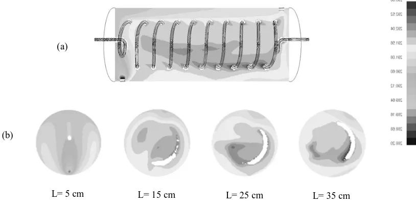
The temperature contour in the vertical plane of the heat exchanger and also various vertical slices along the shell length have been shown in Fig. 7.
Higher temperature values can be seen in the central regions of the shell where the dead zone is formed. Higher temperature values occurred in the dead zones due to the lower turbulent intensity that was followed by a lower heat transfer rate. Therefore, reduction of the dead zone in the central part of the coiled tube can lead to increase in the turbulence intensity and consequently increasing the heat transfer rate. Increasing the coil pitch can have a significant effect on dead zone volume.
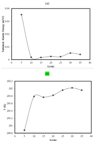
The equivalent value related to temperature and turbulence of Figs. 6 and 7 is shown in Fig. 8. In this figure, variation of turbulent kinetic energy (m2/s2) and temperature at different cross sections along the shell side of the heat exchanger have been reported.
L= 5 cm L= 15 cm L= 25 cm L= 35 cm
Figure 7. The temperature (K) contour (a) in a vertical slice of the heat exchanger and (b) at various planes along the shell (for a better display limited to range of 288.2 – 293 K).
(a)
(a)
(b)
Figure 8. The area weighted average of (a) turbulent kinetic energy (m2/s2) and (b) temperature (K) in planes along the shell.
As can be seen, the turbulent kinetic energy flow rapidly decreases at the first one-third of the shell due to its contact with the coiled tube. This causes a rapid heat transfer between the shell and tube fluid, and consequently the mean temperature of the shell has a sharp increasing rate at this region. Minimum
turbulent kinetic energy has been predicted at the length of 12 cm. After this region, the turbulence intensity increases very slowly along the shell and the mean temperature at different cross section along the shell will increase slowly.
4-3. CFD modeling of new coil pitch design
heat transfer rate in this type of heat exchanger is the coil pitch. Based on successful agreement between the experimental and CFD predicted results, a new design for a coiled tube heat exchanger was modeled in order to study the effect of coil pitch on heat transfer rate. All conditions in the new design are the same as the previous coiled tube (Test number 1 in Table 2), and only the tube pitch has been considered twice (H=6.4 cm). The turbulence intensity of the
previous coiled tube has been compared with the new design.
Fig. 9 shows the comparison between the turbulence intensity of the previous and new coil designs. The contours show a meaningful difference between these two designs. In the new case, where the coil pitch is doubled, the turbulence intensity is increased and consequently the dead zones are reduced. So, the heat transfer rate becomes greater than in the old design.
(a)
(b)
Fig. 9. Comparison of turbulence intensity for: (a) the old coil tube heat exchanger (b) the new design (twice coil pitch) Fig. 10 shows the temperature contour
plots for the two studied cases. The predicted results show that increasing the coil pitch causes a fairly uniform temperature profile
(a)
(b)
Figure 10. Temperature contour for a shell and coiled tube heat exchanger with twice the coil pitch compared the studied heat exchanger. The resulted average turbulent kinetic
energy (k) for heat exchanger with twice the coil pitch was 3.3×10⁻³ m2/s2. Whereas observed k for the old coil tube heat exchanger, 2.9×10⁻³ m2/s2, indicates an increase of about 14% in flow turbulent kinetic energy.
It should be noted that the lower length of the helically coiled tube can be embedded in a certain shell for a higher coil pitch that causes lower total heat transfer. On the other hand, the lower length and higher coil pitch of a coiled tube led to decrease of the pressure drop in the tube (less pump energy consumption) and decrease in the convection heat transfer of the fluid in the tube side due to loose-coiling conditions [8]. Therefore, finding the optimal operating conditions and geometric parameters of the heat exchanger which leads to a trade-off between heat transfer rate and pressure drop can be very useful.
5. Conclusions
However, it should be noted that a lower length of the embedded coiled tube with a higher coil pitch can cause lower total heat transfer.
Nomenclature
A heat transfer area (m2)
Cp specific heat capacity (kJ/kg K)
D coil diameter (m) f friction factor H coil pitch (m) m mass flow rate (kg/s) Q heat transfer rate (W)
T tube side flow temperature (K) T shell side flow temperature (K)
T1 temperature difference at inlet (K)
T2 temperature difference at outlet (K)
U overall heat-transfer coefficient (W/m2 K)
Subscripts
i inlet
LMTD log mean temperature difference (K) o outlet/outer/overall
s shell side
t tube side
References
[1] Zhou, Y., Yu, J. and Chen, X., "Thermodynamic optimization analysis of a tube-in-tube helically coiled heat exchanger for Joule–Thomson refrigerators", Int. J.
Therm. Sci., 58, 151 (2012).
[2] Yi, J., Liu, Z. H. and Wang, J., "Heat transfer characteristics of the evaporator section using small helical coiled pipe in a looped heat pipe", Appl. Therm. Eng., 23 (1), 89 (2003).
[3] Wongwises, S. and Polsongkram, M., "Evaporation heat transfer and pressure drop
of HFC-134a in a helically coiled concentric tube-in-tube heat exchanger", Int. J. Heat
Mass Transf., 49 (3-4), 658 (2006).
[4] Guo, L. J., Feng, Z. P., Chen, X. J., "Pressure drop oscillation of steam–water two-phase flow in a helically coiled tube",
Int. J. Heat Mass Transf., 44 (8) 1555 (2001).
[5] Vashisth, S., Kumar, V. and Nigam, K. D. P., "A review on the potential applications of curved geometries in process industry",
Ind. Eng. Chem. Res., 47 (10), 3291 (2008).
[6] Naphon, P. and Wongwises, S., "A review of flow and heat transfer characteristics in curved tubes", Renew. Sust.
Energ. Rev., 10 (5), 463 (2006).
[7] Ebrahimnia-Bajestan, E. and Niazmand, H., "Convective heat transfer of nanofluids flows through an isothermally heated curved pipe", J. Chem. Eng., 8 (2), 81 (2011).
[8] Beigzadeh, R., Rahimi, M. and Parvizi, M., "Experimental study and genetic algorithm-based multi-objective optimization of thermal and flow characteristics in helically coiled tubes", Heat. Mass.
Transfer., 49, 1307 (2013).
[9] Beigzadeh, R. and Rahimi, M., "Prediction of heat transfer and flow characteristics in helically coiled tubes using artificial neural networks", Int. Commun.,
Heat. Mass. Transfer., 39 (8), 1279 (2012).
[10] Beigzadeh. R., Rahimi, M., "Prediction of thermal and fluid flow characteristics in helically coiled tubes using ANFIS and GA based correlations", Int.
Commun. Heat. Mass. Transfer., 39 (10),
1647 (2012).
203 (2009).
[12] Salimpour, M. R., "Heat transfer characteristics of a temperature-dependent-property fluid in shell and coiled tube heat exchangers", Int. Commun. Heat. Mass.
Transfer., 35 (9), 1190 (2008).
[13] Eiamsaard, S., Wongcharee, K. and Sripattanapipat, S., "3-D Numerical simulation of swirling flow and convective heat transfer in a circular tube induced by means of loose-fit twisted tapes", Int.
Commun. Heat. Mass. Transfer., 36 (9), 947
(2009).
[14] Moradi, M., Etemad, S. Gh. and Moheb A., "laminar flow heat transfer of a pseudoplastic fluid through a double pipe heat exchanger", Iran. J. Chem. Eng., 3 (2), 13 (2006).
[15] Wang, Y., Liu, Z., Huang, S., Liu, W. and Li, W., "Experimental investigation of shell-and-tube heat exchanger with a new type of baffles", Heat. Mass. Transfer., 47, 833 (2011).
[16] Chen, G. D., Zeng, M. and Wang, Q., "Experimental and numerical studies on shell-side performance of three different shell-and-tube heat exchangers with helical baffles", J. Enhanced Heat Trans., 18 (5), 449 (2011).
[17] Conté, I., Peng, X. F. and Wang, B. X., "Numerical investigation of forced fluid flow and heat transfer from conically coiled pipes", Numer. Heat. Tr. A-Appl., 53 (9), 945 (2008).
[18] Piazza, I. D. and Ciofalo, M., "Numerical prediction of turbulent flow and heat transferin helically coiled pipes", Int. J.
Therm. Sci., 49 (4), 653 (2010).
[19] Jayakumar, J. S., Mahajani, S. M.,
Mandal, J. C., Vijayan, P. K. and Rohidas, B., "Experimental and CFD estimation of heat transfer in helically coiled heat exchangers", Chem. Eng. Res. Des., 86 (3), 221 (2008).
[20] Jayakumar, J. S., Mahajani, S. M., Mandal, J. C., Iyer K. N. and Vijayan, P. K., "CFD analysis of single-phase flows inside helically coiled tubes", Comput. Chem. Eng.,
34 (4), 430 (2010).
[21] Shokouhmand, H., Salimpour, M. R.
and Akhavan-Behabadi, M. A.,
"Experimental investigation of shell and coiled tube heat exchangers using wilson plots", Int. Commun. Heat Mass Transfer.,
35 (1), 84 (2008).
[22] Fluent 6.2®, Fluent Inc, Lebanon, NH, USA, 2005.
[23] Launder, B. E. and Spalding, D. B., "The numerical computation of turbulent flows", Comput. Meth. Appl. Mech. Eng., 3