Research Journal
Volume 10, No. 32, Dec. 2016, pages 101–108
DOI: 10.12913/22998624/65130 Research Article
STUDY OF CHIP IGNITION AND CHIP MORPHOLOGY AFTER MILLING
OF MAGNESIUM ALLOYS
Ireneusz Zagórski1, Józef Kuczmaszewski1
1 Department of Production Engineering, Faculty of Mechanical Engineering, Lublin University of Technology, Nadbystrzycka 36, 20-618 Lublin, Poland, e-mail: [email protected], [email protected]
ABSTRACT
The paper analyses the impact of specified technological parameters of milling (vc, fz, ap) on time to ignition. Stages leading to chip ignition were analysed. Metallographic images of magnesium chip were presented. No significant difference was observed in time to ignition in different chip fractions. Moreover, the surface of chips was free of products of ignition and signs of strong oxidation.
Keywords: magnesium alloys, chip morphology, time to ignition, chip ignition, high-speed dry milling.
INTRODUCTION
Although magnesium alloy has been known since the World War II, it is still an interesting structural material. In recent years, there has been a growing interest in magnesium alloys, which are considered as innovative structural materials, particularly in the context of the aircraft indus-try, which is seen to be at the forefront of modern technology. Manufacturing modern aircraft parts frequently requires quick removal of any existing machining allowance. In addition, the lightness of structure in manufactured aircrafts or helicopters is paramount. In the aerospace industry, the ma-jority of parts is machined by milling, which is a preferred operation in most roughing and finish-ing applications. Time factor is crucial in remov-ing machinremov-ing allowance, hence the popularity of high-performance machining methods, such as HSM, HPC or HSC, which however, necessi-tate the application of snecessi-tate-of-the-art machining centres (high-speed electrospindles) and modern tool materials. High-performance milling offers numerous advantages: high quality surface finish, production costs reduction (grinding is unnec-essary), increased efficiency and performance,
which leads to reducing machining time. A wide-spread application of magnesium alloy as a struc-tural material in different branches of industry in-creases the importance of its rational and precise machining.
THE STATE OF KNOWLEDGE
The classification of methods for machining magnesium alloys accounts for the character of the realised process and formulated aims [15]: dry or minimum quantity lubrication cutting, with water-immiscible fluids including oils or emulsions. Dry machining of magnesium alloys entails high risk of chip ignition, particularly of small chips. Therefore, chip dimensions and size are crucial in machining magnesium, which arises from susceptibility of magnesium chips to ignition during milling. The analysis of chip frac-tions and specific weight of formed chips is fre-quently used to determine machining safety. Chip fragmentation occurs during magnesium alloy milling in certain conditions, and consists in chip segmentation during forming. In addition, igni-tion in dry cutting can occur as a result of flank
built-up [8, 9]. This unfavourable build-up can be reduced if proper tool coating and PCD tools are applied. Another advantage of PCD tools is that the finished surface is of excellent quality, comparable to surfaces finished by grinding. Fin-ishing operations are also used in removing burr from light alloys Al or Mg, in which case bur-nishing finds application [14].
Owing to the fact that the risk of ignition in machining is connected with elevated tempera-ture during chip formation, the temperatempera-ture is usually measured on the chip or in the area just above the rake face. Safety analysis in machining may concern several phenomena, e.g. analysis of chip fractions formed during machining, monitor-ing ignition in dry cuttmonitor-ing, analysis of time to chip ignition (usually away from the machine tool), chip morphology (observation with optic micros-copy and SEM) or stages of chip morphology change prior to chip ignition [4, 8, 9].
It is possible to control the shape and form of chips during milling through adjusting tech-nological parameters of machining. The efforts during machining should be focused on produc-ing chip that would be least susceptible to ig-nition. A particular type of formed chip, hence the type of ignition, depends on: cutting speed, depth of cut and the type of magnesium alloy machined [2, 3, 9]. It is crucial to determine the ignition point, i.e. temperature characteristic for a given type of Mg alloy. In related studies, the analyses concern the importance of cerium (Ce) and aluminium (Al) on ignition point and resis-tance of magnesium alloys to oxidation. Among other factors, studies show that resistance to ig-nition also depends on the presence of yttrium (Y) [11, 12, 19, 21]. Chip ignition is retarded with the increase of Al content in alloy. Chip ignition studies are conducted at depths of cut (1÷1000μm) that are rarely applied in industrial conditions. In the depth of cut range of 1÷80 μm, chip ignitron during machining was ob-served [6, 7, 20].
For theoretical considerations, the unde-formed chip thickness is of great significance in modelling the cutting process. In studies, sev-eral models for determining chip thickness are introduced, beginning from basic, such as linear or circular interpolation [13], to more advanced analysis of actual tool trajectory in trochoidal tool path. The local undeformed chip thickness can be calculated from the equation of so-called tran-scendental deduction [10].
The classification of chips can be adopted from the Polish Norm PN-ISO 3685:1996 (and its English equivalent ISO 3685:1993 Tool-life testing with single-point turning tools) [16]; how-ever, the standard in question concerns turning steel or cast iron workpiece with high-speed steel, cemented carbide or ceramic tools. In addition, chip characteristics are dependent on other fac-tors, e.g.: workpiece material, cutting edge mate-rial and geometry, its wear and position, cutting parameters and other cutting conditions. Further-more, the importance of cutting tool geometry, stress and strain conditions, i.e. decohesion of material in chip formation zone [5, 8].
Magnesium chip morphology is another factor of considerable significance in safety of machin-ing. The methodology for the evaluation of ma-chining safety should include elements that will enable determination of built-up or burnt surfaces on the chip. Such a risk occurs when the melt-ing point temperature of a workpiece material is reached during machining (for Mg alloys approx. 500°C). The concept of chip morphology con-cerns mainly chip structure and geometry. Magne-sium alloy chips have a characteristic structure: on the one hand, their surface is smooth (as a result of the contact between the rake face and chip), on the other hand, frequently chips of lamellar structure are formed. Lamellae are regular structures lay-ered in parallel to each other [4, 6, 9].
During HSM, increasing cutting speed (at constant material removal rate) results in de-crease in cutting forces, which in turn dede-creases the amount of heat generated in the cutting zone and minimises chip deformation [1]. It is there-fore crucial to realise the machining process with-in cuttwith-ing data denotwith-ing high-speed machwith-inwith-ing.
At temperatures exceeding 500°C small frac-tions of loose Mg chips can ignite, and 623°C is the nominal ignition temperature for magnesium in the presence of oxygen. At the temperature of 650°C, magnesium melts, 1107°C is magnesium boiling point and the combustion temperature is above 2000°C (ignition point is lower than melt-ing point) [15].
PROGRAMME, METHODOLOGY AND AIM
OF STUDY
selecting such cutting data as: cutting speed, feed and depth of cut, with a view to risk of ignition, defined by indices analysed in the study. Select-ing proper relations between the cuttSelect-ing param-eters in question is paramount to obtaining excel-lent stability and effectiveness of the process. The main aim was to analyse ignition time, stages in chip morphology change prior to ignition and mi-croscopic observation of chips.
Milling operations were carried out on a ver-tical machining centre Avia VMC800HS with a TiAlN-coated carbide cutter 16 mm in diameter. The selected working engagement was constant, at
ae = 14mm, and changing technological parameters
of milling were: ap = (0.5÷6) mm, fz = (0.05÷0.3)
mm/tooth and vc = (400÷1200) m/min. The tests
were conducted on two types of magnesium al-loys: AZ91HP cast alloy and AZ31 alloy for plas-tic working applications. The two analysed mate-rials are widely used in industry. Table 1 shows the chemical composition of the analysed magnesium alloys, e.g. AZ91 alloy has an 89.587% content of pure Mg, while AZ31 95.31%.
Metallographic examination of chips was car-ried out with Leica DFC450-C digital microscope camera. Time to ignition and ignition temperature were measured on a custom test set-up outside of the machine tool. With a view to comparative analysis, stages in chip morphology change prior to chip ignition were analysed with Phantom 9.1 high-speed camera. Ignition time measurement was carried out 5 times for specified technologi-cal parameters of milling.
For the purpose of description, two terms are used in the paper: chip fraction and chip fragmen-tation. Fraction is a population of elements of a particular size or dimensions. Fragmentation is a phenomenon occurring during machining con-sisting in formation of an intermediate chip frac-tion of different shape and mass, alongside the leading fraction (prevailing and characteristic). It is an unfavourable condition due to the danger of ignition of small chip fractions and swarf pollut-ing the workspace of the machine tool. The divi-sion into leading (main) fraction and intermedi-ate fractions was based on the shape and mass of chip. The shape of chip determined the leading fraction (of the highest mass per unit area and the most representative in quantitative terms) and intermediate fractions. The intermediate fraction was defined in two stages: as a fraction dissimilar to the leading fraction, and as a fraction of mass per unit area which is approx. 50% lower than the chip of leading fraction.
Figure 2 shows a visualisation of a set-up for measurement of time to ignition of chip formed dur-ing milldur-ing at changdur-ing technological parameters.
The methodology and the programme of tests determine that it is important to search for the suitable set of solutions, for which the aims of the work are realised to the greatest extent, in the space of independent variables.
Figure 3 shows a sheathed thermocouple dedicated for surface temperature measurements (of e.g. heating plate) and a temperature control-ler. The thermocouple is designed for measuring
Fig. 1. General plan of study
Table 1. Chemical composition of tested magnesium alloys [17, 18]
Alloy Chemical composition [%]
Cu Mn Mg Zn Si Fe Al other
temperature of liquids, gases and on the surface [22]. The temperature sensor works with different input types, including thermocouples K, J, T and E, providing measurement accuracy of ±[0.2% + 0.6°C]. The types of thermocouples denote the sheath material, i.e.: J – Fe-CuNi, T – Cu-CuNi, E – NiCr-CuNi. The type of a thermocouple used depends on the range of temperatures to be mea-sured.
Time to ignition was measured 5 times for each chip fraction. In addition, maximum and av-erage temperature of the heating plate was given.
TEST RESULTS AND ANALYSIS
Figure 4 shows the impact of cutting speed vc and feed per tooth fz on average time to chip ignition.
There is no clear-cut correlation between the
change of vc and fz and increase or decrease of
time to ignition of leading and intermediate
frac-tions of chips. In the case of vc change and the
leading chip fraction, AZ91HP magnesium al-loy, the average time to ignition rises whereas in AZ31 no particular tendency is observed (Fig. 4a). The change of feed per tooth (Fig. 4b)
pro-duced two notable tendencies. At fz = (0.05÷0.15)
mm/tooth time to ignition for the leading chip
fraction increases. At fz = (0.15÷0.3) mm/tooth,
the following effects are observed: time to igni-tion of AZ91HP alloy chips decreases, whereas in AZ31 alloys, further increase is observed.
An important observation is that, as shown in Figure 4, even in intermediate chip fractions, in particular in “intermediate fraction c”, no sharp decrease in time to ignition occurs, compared to the leading chip fraction, despite a great differ-ence in mass per unit of both fractions (as in [8]). This information is of great significance to safety precautions during machining, as even the inter-mediate fraction does not ignite instantly: even chips of small mass (m = 0.0003 g) require a cer-tain length of time to ignite.
Figure 5 analyses the impact of depth of cut
ap on average time to chip ignition. In the case of the leading chip fraction, the change in the depth of cut (Fig. 5) resulted in no significant change of
Fig. 2. Chip ignition test set-up
Fig. 3. Type K sheathead thermocouple (thermo-couple TP-102a-120, sheath material NiCr-NiAl) and
UT-320 temperature controller [22]
Fig. 4. Time to ignition of different chip fractions at different milling parameters: a) cutting speed vc (fz =
0.15 mm/tooth, ap = 6 mm; Tmax = 525.4±1.7°C, Tav = 521.8±1.6°C), and b) feed per tooth fz (vc = 800 m/
min, ap = 6 mm; Tmax = 529.3±1.7°C,
Tav = 525.8±1.7°C) b)
time to ignition. No direct correlation was noted between the change in average mass per unit of the leading chip fraction on its average time to ignition parameter. The analysis of intermediate chip fractions showed that at changing depth of cut (Fig. 5) in the majority of cases the time to ignition values were comparable to that of the leading chip fraction. Longer time to ignition ob-served in AZ91HP chips could result from differ-ences in alloy additions in the analysed Mg alloys. The characteristic changes in chip morpholo-gy at stages prior to ignition were analysed for the
following technological parameters: ap=1.5mm
fz=0.05mm/tooth vc=300m/min. The examination
was carried out to present the chip morphology stages leading to chip ignition. Figs. 6 and 7 show phases prior to ignition of analysed chip fractions.
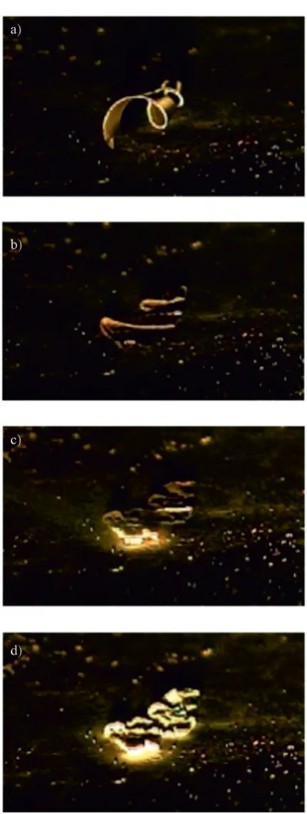
Fig 6. shows changes in chip morphology preceding ignition of AZ31 alloy chip.
Chip ignition, observed on a special heating plate, is preceded by strong thermal deformation of the analysed chip in response to high
tempera-Fig. 5. Time to ignition of different chip fractions at different depths of cut ap: a) fz = 0.05 mm/tooth; Tmax = 520.8±1.6°C, Tav = 515.0±1.6°C; b) fz = 0.15
mm/tooth; Tmax=525.2±1.7°C, Tav = 521.2±1.6°C
Fig. 6. Subsequent stages prior to AZ31 alloy chip ignition: a) the contact of chip with the heating plate,
b) thermal deformation of chip, c) initial ignition of chip, d) full ignition of chip; ap = 1.5 mm fz = 0.05
mm/tooth vc = 300 m/min
ture. The vision camera used in tests provided im-ages that allowed us to measure time to ignition and time needed to cause thermal deformation of chip, the latter measured from the moment of
c)
d)
a)
b)
b)
chip-plate contact to chip deformation. The test provides crucial information from the point of view of ensuring secure conditions of machining in terms of potential chip ignition occurrence.
Additional tests for the leading fraction chip ignition were conducted for chips produced at the
following cutting conditions: AZ91HP alloy, vc =
1200 m/min, fz = 0.15 mm/tooth, ap = 6 mm. The
ignition of the leading fraction chip was initiated by direct ignition from intermediate chip frac-tions (the intermediate fraction was supposed to ignite the leading fraction). 5 test attempts were carried out for each intermediate chip fraction, then the leading fraction chip was replaced and the procedure was repeated. In chips produced in the aforementioned conditions the following ob-servations were made:
• failure to ignite the leading fraction chips by
two intermediate fractions: “b” (average mass 0.0071 g) and “c” (average mass 0.0003 g),
• successful ignition of the leading fraction
chips by the intermediate fraction “a” (aver-age mass 0.0176 g, i.e. approx. a half of the leading fraction mass).
The conducted tests conclude that even if small chips are ignited during milling, the re-maining larger chip fractions will not become ig-nited. Obviously, it is imperative that machining parameters that could cause excessive fragmenta-tion of chips potentially leading to ignifragmenta-tion during the process should not be applied, as the formed chip could additionally leave swarf and debris in-side the machine tool.
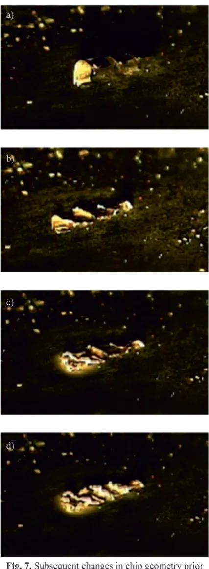
Figure 7 shows phases prior to ignition of AZ91HP alloy chip.
Metallographic examination of thermally de-formed chip morphology becomes an important tool in analysis of ignition risk during milling. Leica DFC450-C digital microscope camera en-abled us to analyse the built-up edges occurring on the side surface of formed Mg chip. Such analysis was conducted for chip produced at maximum (in the analysed study) technological parameters of machining.
Figure 8 shows photographic images of the following magnesium alloy chips: chips formed at maximum cutting speed vc and feed per tooth fx (Fig. 8a and 8b), chips subjected to high temper-ature (approx. 500 ºC), chips where no ignition occurred (Fig. 8c and 8d), chips that succumbed to ignition on the heating plate at approx. 500 ºC (Fig. 8e and 8f).
No characteristic built-up or burnt surfaces or edges of chips presented in Figures 8a and 8b can be noticed. The surface of chips shown in Fig-ure 8c and 8d is considerably darker compared to
Fig. 7. Subsequent changes in chip geometry prior to AZ91HP alloy chip ignition: a) the contact of chip
with the heating plate, b) thermal deformation of chip, c) initial ignition of chip, d) full ignition of chip;
ap = 1.5 mm fz = 0.05 mm/tooth vc = 300 m/min
d)
c)
b)
chips immediately after cutting. This occurred as a result of strong oxidation of chip surface initi-ated at the point of chip-plate contact. The images in Figures 8e and 8f show ignition products on the surface of machined chips.
CONCLUSIONS
The conducted analytical and experimental works lead to the following general conclusions: 1. Chip fragmentation is an unfavourable
phe-nomenon in machining, mainly due to a
high-er risk of ignition of inthigh-ermediate fractions of chips and debris in the workspace.
2. The conducted tests indicate that in the ma-jority of cases longer time to ignition was noted in AZ91HP cast alloy chips; this could result from a higher content of alloy compo-nents and lower content of pure Mg.
3. Time to ignition was in the range of several to tens of seconds, i.e. several times more than the actual chip formation time.
4. Ignition of Mg alloy chips is preceded by strong thermal deformation of chip, observed in high-speed camera images.
Fig. 8. Metallographic images of Mg alloy chips: a) AZ91HP alloy (vc= 1200 m/min), b) AZ31 alloy (vc = 1200 m/min), c, d) chip that did not ignite when subjected to high temperature (≈500°C),
e, f) Mg alloy ignition products
a) b)
f)
e)
5. Ignition of the leading fraction of chips can be initiated by an ignited intermediate frac-tion only if the mass of intermediate fracfrac-tion chips is equal to or higher than approx. 50% of the leading fraction chip mass. In prac-tice, this means that the uncontrolled self-ignition of the most dangerous intermediate dust chip fraction cannot initiate ignition of the leading fraction.
6. The presented metallographic images show that no products of ignition or strong oxida-tion were present on the chip surface. This conclusion is of great significance to ma-chining safety during dry milling of analysed magnesium alloys.
7. Microscopic examination of chip formed during machining at maximum analysed technological parameters of cutting showed distinctly visible fragments of chips. No char-acteristic built-up edges were observe, which could indicate a cutting zone dangerous from the point of view of self-ignition.
REFERENCES
1. Adamski W. Manufacturing development strate-gies in aviation industry. Advances In Manufactur-ing Science and Technology, 34(3), 2010, 73–84. 2. Akyuz B. Machinability of magnesium and its
al-loys. TOJSAT: The Online Journal of Science and Technology, 1(3), 2011, 31–38.
3. Arai M., Sato S., Ogawa M. and Shikata H.I. Chip Control in Finish Cutting of Magnesium Alloy. Journal of Materials Processing Technology, 62(4), 1996, 341–344.
4. Fang F.Z., Lee L.C. and Liu X.D. Mean Flank Temperature Measurement in High Speed Dry Cut-ting. Journal of Materials Processing Technology, 167(1), 2005, 119–123.
5. Guo Y.B. and Salahshoor M. Process mechanics and surface integrity by high-speed dry milling of biodegradable magnesium–calcium implant alloys, CIRP Annals - Manufacturing Technology, 59(1), 2010, 151–154.
6. Hou J.Z., Zhou W. and Zhao N. Methods for Pre-vention of Ignition during Machining of Magne-sium Alloys. Key Engineering Materials, 447–448, 2010, 150–154.
7. Hou J.Z., Zhou W. and Zhao N. Effect of Cutting Parameters on Ignition of AM50A Mg Alloy
dur-ing Face Milldur-ing. Materials and Manufacturdur-ing Processes, 25(10), 2010, 1048–1051.
8. Kuczmaszewski J. and Zagórski I.: Badania frag-mentowania wiórów w procesie frezowania stopów magnezu. Mechanik, 8–9, 2014, 321–328.
9. Kuczmaszewski J. and Zagórski I. Badania masy, temperatury zapłonu oraz temperatury wiórów podczas skrawania wybranych stopów magnezu. Mechanik, 10, 2012, 824–828.
10. Li H.Z., Liu K. and Li X.P. A new method for de-termining the undeformed chip thickness in mill-ing. Journal of Materials Processing Technology, 113(1–3), 2001, 378–384.
11. Lin P.-Y., Zhou H., Li W., Li W.-P., Sun N. and Yang, R. Interactive effect of cerium and aluminum on the ignition point and the oxidation resistance of magnesium alloy. Corrosion Science, 50(9), 2008, 2669–2675.
12. Liu M., Shih D.S., Parish C. and Atrens A. The ig-nition temperature of Mg alloys WE43, AZ31 and AZ91. Corrosion Science, 54, 2012, 139–142. 13. Lotfi Sai, Bouzid W. and Zghal A. Chip thickness
analysis for different tool motions for adaptive feed rate. Journal of Materials Processing Technology, 204(1–3), 2008, 213–220.
14. Matuszak J. and Zaleski K. Effect of Brushing Pa-rameters Upon Edge States After Wire Brushing of AZ91HP Magnesium Alloy, Advances in Science and Technology Research Journal, 7(20), 2013, 55–60. 15. Oczoś K.E. Rozszerzenie granic stosowalności
stopów magnezu. Mechanik 5-6, 2009, 386–400. 16. Polska Norma. Badanie trwałości noży tokarskich
punktowych, PN–ISO 3685:1996.
17. Polska Norma. Magnez i stopy magnezu – Gąski i odlewy ze stopów magnezu, PN–EN 1753:2001. 18. Polska Norma. Magnez i stopy magnezu – Anody,
gąski i odlewy z magnezu i stopów magnezu – Sys-tem oznaczenia, PN–EN 1754:2002.
19. Ravi Kumar N.V., Blandin J.J., Suery M. and Gros-jean E. Effect of alloying elements on the ignition resistance of magnesium alloys. Scripta Materialia, 49(3), 2003, 225–230.
20. Zhao N., Hou J. and Zhu S. Chip ignition in re-search on high-speed face milling AM50A mag-nesium alloy. Second International Conference on Mechanic Automation and Control Engineering, Inner Mongolia, China 2011, 1102–1105.
21. Zhou H., Li W., Wang M. and Zhao Y. Study of ignition proof AZ91D magnesium alloy chips with cerium addition. Journal of Rare Earth, 23(4), 2005, 466–469.
![Table 1. Chemical composition of tested magnesium alloys [17, 18]](https://thumb-us.123doks.com/thumbv2/123dok_us/8808198.1775732/3.595.71.530.711.770/table-chemical-composition-tested-magnesium-alloys.webp)
![Fig. 3. Type K sheathead thermocouple (thermo-couple TP-102a-120, sheath material NiCr-NiAl) and UT-320 temperature controller [22]](https://thumb-us.123doks.com/thumbv2/123dok_us/8808198.1775732/4.595.305.522.76.395/sheathead-thermocouple-thermo-couple-sheath-material-temperature-controller.webp)