0 INTRODUCTION
Quality parameters of threads when machining depend both on material properties and on a number of technological factors: method and arrangement of shape-forming, tool structure and geometry, as well as cutting conditions [1] to [10]. The technology employed for making threaded parts has to provide a set of geometrical parameters and characteristics of the state of the surface layer, thus determining the performance characteristics of the threaded connection dependent on its functional purpose.
Thread surfaces – external or internal – are obtained by three principal methods: cutting, plastic working, and a combined method [2] to [5], [7], [8], and [11] to [15]. The two latter methods have a number of advantages as regards guaranteeing the major quality characteristics of all types of threaded connections. This is attributed to the greater hardness of the surface layer of the thread turns, the positive effect of surface compressive stresses, stable high accuracy, and low roughness of surfaces.
Тhe use of combined machining and plastic
deformation of external threads is widespread and is the prevailing method used for a number of fastener threaded parts [8]. For internal threads, having lower manufacturing producibility, these working methods, regardless of their obvious advantages, find limited application.
It is known that over 60% of the parts of modern machines and mechanisms have threaded holes. Making internal threads, especially of small sizes, is a manufacturing problem, owing to the insufficient strength and reliability of the tools (taps) used. The design and use of new tool materials, the application of optimum technological equipment and new kinds of lubricating-cooling agents do not solve the problems of highly productive, quality manufacturing of internal threads. Continuous improvement in tap design, geometry optimization of tap bodies, and
improvement of manufacturing technology of taps is necessary, since these are the most widely used tools for machining internal threads.
The objective of this paper is the structural and technological development and experimental study of a new design of cutting-deforming taps which have enhanced strength and reliability, combining both methods of formation – cutting and plastic deformation. By creating these taps, opportunities are offered for intensifying the internal thread forming process accompanied by quality improvement. The objective of this paper has been formulated on the basis of comparison, analysis and quality evaluation of advantages and disadvantages of methods and tools for making internal threads with diameters ranging from 1 to 16 mm (Table 1).
1 DESIGN AND STUDY OF COMBINED CUTTING-DEFORMING TAPS
1.1 Analysis of the Possibilities for Enhancing the Strength of Taps
In order to determine tap, it is necessary to take into account the shape and size of the operating tool elements as a geometric body, as well as the size and character of change in the forces affecting tool wear.
During internal thread forming, taps are mainly subjected to torsional loads and sometimes to bending loads (when the hole and tool axes are displaced). Therefore, tangential stresses are most dangerous for taps occurring where the tool tends to be twisted by the applied torque. The destruction (breaking) of these tools depends mainly on the size of the maximum torque and on their cross-section.
To determine the size of the crushing torque, special test specimens of high-speed steel HSS with a
hardness of НRC 63 were made. One of the specimens
has a cross-section of three-sided relieved profile of chipless tap with an M8 ground thread with the
Combined Cutting-deforming Taps
Aleksandrova, I.S. – Ganev, G.N.
Irina Stefanova Aleksandrova* – Gancho Nenkov Ganev Теchnical University of Gabrovo, Bulgaria
Enhancement of the efficiency and quality of internal thread forming requires continuous improvements in the design of the tools used and optimization of their body geometry. A new design for cutting-tightening taps with enhanced strength and reliability for forming thread surfaces by combining the methods of cutting and plastic deformation are proposed in this paper. An experimental study of torque was carried out during thread forming employing the designed combined tool and the major factors having an effect on the tool serviceability were defined. An algorithm for designing cutting-tightening taps has been proposed, which guarantees a minimum torque in thread forming.
following dimensions: inside diameter d1 = 6.65 mm; outside diameter d = 8.144 mm; mean diameter d2 =
7.30 mm; height of relieving k = 0.48 mm. The cross-
section of the test specimen is Sn1 = 29.175 mm2; and it is determined according to the relationship [4]:
Sn1 d k1 2 Ak2
4
=
(
−)
π − π, (1)where A = 1 is a constant for the three-sided relieved tap.
Таble 1. Quality evaluation of methods and tools for cutting internal threads
Parameters Tapping Threading with fluteless taps (by plastic deformation) Geometric accuracy
of thread
satisfactory good
Degree of roughness of thread
satisfactory good
Strength properties of threads
satisfactory good
Applicability to various materials
good low (for working metals with high plasticity)
Manufacturing producibility of tool
good satisfactory
Output low good Tool life short satisfactory Strength of the
bearing section of the tool
low good
The second specimen is a conventional M8 thread-cutting tap. Due to the complicated profile of the cross-section of the thread-cutting taps, universally valid formulae for calculating its area are not available in literature. However, the area can be determined graphically in the AutoCAD environment and it is Sn2 = 10.2 mm2.
After loading the test specimens the following results were obtained for the breaking torque Md and failure tangential stresses τ:
• for the chipless specimen М8; Md1 = 65.6 Nm;
τ1 = 670 MPa;
• for specimen М8 with chip flutes; Md2 = 21.7 Nm; τ2 = 640 MPa.
The relationship between the determined values of the breaking torques for chipless and thread-cutting taps characterizes the common safety margin (Eq. 2), since the determined values for failure stresses were approximately identical:
K M
M
S d
d
= 1 = =
2
65 6 21 7 3 023
.
. . . (2)
The analysis made shows that the chipless tap is over three times stronger than the conventional thread-cutting tap. This led us to the idea of designing a tap with a forming part, which encloses a cutting part that removes the whole or most of the additive as in conventional thread-cutting taps, and a tightening part, which through plastic deformation finishes and strengthens the thread. The calibrating part of the tap is shaped as chipless fluteless taps and thus the tool strength is significantly enhanced.
1.2 Design of Thread-tightening Taps with Enhanced Strength
In accordance with the theoretical-experimental anlaysis, a combined cutting-deforming (thread-tightening) tap was designed, which encloses a forming part that has a length of lf and a calibrating part. The cross-sections of the forming and calibrating parts are shaped and relieved as chipless taps (Section
e-e) (Table 2), which enhances the tool strength. On
the front part of the tap at length ls, a certain number of chip flutes with the geometry required for cutting are made. The forming part (lf) of the tap consists of two zones: cutting – having a length of lcand tightening - having a length of ld, shaped at angles χr1 and χr respectively, where χr1 ≥ χr (Table 2). The lengths of the cutting and tightening parts are determined by the location of point Т (the point where the chip flute inclined at angle λ intersects the axial plane of the tap) and by the length of the forming part, lf. The teeth positioned in front of point Т (Section a-a) are cutting with a positive clearance angle defined by the relieving on the flank. The teeth positioned after point Т (Section b-b), are tightening owing to their negative clearance angle shaped by the rising slope of the relieving curve of the preceding tooth of the tap.
Depending on the position and length of the chip flutes with regard to the forming part with length lf and the size of angle λ, various arrangements are possible (Table 2), which define the tap as cutting or cutting-tightening.
1.2.1 Taps with Inclined Chip Flutes λ > 0° and Variable Rake γ along the Chip Flute
If lf≥ lcand diameter d0 of the preliminary drilled hole is within: d2 ≥ d0 ≥ d1, the tap is cutting-tightening. For thread diameters less than dT (Table 2), the tap is cutting.
chip flutes on its calibrating part, which significantly enhances its strength and reduces the chance of breaking.
1.2.2 Taps with Straight Chip Flutes (λ = 0°) and Invariable Rake along the Chip Flute
If lc= ls ≤ lf and diameter d0 of the preliminary drilled hole is within: d2 ≥ d0 ≥ d1, the tap is cutting-tightening.
The cutting part with angle χr1 is additionally relieved (Section f-f, Table 2).
If lc= ls > lf , the tap is cutting.
1.3 Experimental Study of the Designed Thread-tightening Taps
The internal thread forming process employing the designed cutting-deforming taps and their
Таble 2. Taps – geometrical and structural elements
Type of tap Shapes of the forming part of the tap cylindrical taper
Deforming (chipless) tap:
The forming part lf is relieved with a height of k at angle χr.
Inclined chip flutes at angle λ > 0°
Cutting-deforming tap:
• lc≤ lf ; d2 ≥ d0 ≥ d1; d3 = d0 – δ;
• angle γ is variable (γ≥ 0) for the forming part lf .
Cutting tap:
• lc> lf ; d3 = d0 – δ;
• angle γ is variable: γ =arcsin2a .
dii
Straight chip flutes (λ = 0°) Cutting-deforming tap:
• lc≤ lf ; d2 ≥ d0 ≥ d1;
• cutting part lc is relieved with a height of k at angle χr1;
• tightening part ld is relieved with a height of k at angle χr. Cutting tap:
• lc≥ lf ; d0 ≥ d1; d3 = d0 – δ;
• cutting part lc is relieved with a height of k at angle χr1;
serviceability depend on a great number of factors, which can be divided into two large groups:
• Factors determined by the tool structure: pitch p and diameter d of the thread, lengths of cutting and tightening parts lc and ld, number of flutes, geometrical elements of the forming part (inclination angle of the chip flute λ, rake angle γ, clearance angle α, angles of cutting and tightening parts χr1 and χr), and the arrangement for manufacturing the forming part;
• Factors determined by the type of machining: material to be machined (hardness, chemical composition, and structure), thread length, type of hole – blind or through, diameter of the preliminary drilled hole d0, plastic deformation additives vs. cutting additives ratio (η [%]), lubricating-cooling liquid type, intensity and feeding method in the cutting zone, machining conditions, etc.
Preliminary experimental studies of the serviceability of the designed cutting-deforming tap have been conducted. The maximum torque Mbmax in thread forming is taken to be a parameter for evaluating serviceability. For strength reasons, Mbmax should be deliberately kept at a minimum, especially if taking into account that the cross-section of the tap is limited by the thread diameter.
Four thread-tightening taps M8 with three
flutes (z = 3) of high-speed steel HSS have been made
for conducting the study. Their design parameters are
listed in Table 3.
The studied taps operate under identical conditions and the ratio of additives for plastic deformation to additives for cutting is (Table 2, Table
3):
η = − −
=
d d d dT2
2
100 17 5. % (3)
Таble 3. Еxperimental conditions
No. λ [grad] lc [mm] χr[grad] χr
1 [grad]
1 0 10.5 2 2.45 2 3 10.05 2 2.54
3 6 5.7 2 4.5
4 9 3.8 2 6.76
d = 8.144–0.02 mm; d2 = 7.323–0.02 mm; d3 = 6.9 mm;
γmax = 10°; k = 0.48 mm; d0 = 7+0.03 mm; dT = 7.8 mm; l d
tg
c= 32sinγλmax(λ> 0°)
χ λ
γ
r T
T 1=
− −
(
)
+ −
(
)
arctg d d d tg
d d d
2 1
1 sin
.
max
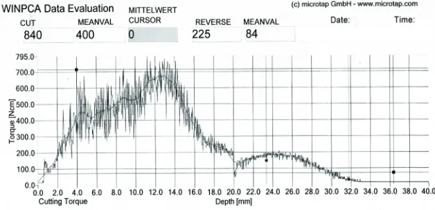
The material machined is steel C45 and Castrol Carecut ES1 thread oil was used as a lubricating-cooling liquid. The length and diameter of the through holes being worked are respectively: l0= 13 mm;and d0 = 7+0.03 mm. The torque is measured at a purpose
stand for torque testing Мicrotap at constant speed of
rotation n = 315 min–1.
Four experiments were conducted and during each experiment four observations were made. The character of the torque variations at λ = 0° is shown in
Fig. 1, and at λ > 0° in Fig. 2. The measured values of
maximum torque Mbmax are presented in Table 4. The analysis of the experimental results obtained shows that the magnitude of the maximum torque during thread forming depends on the length of the cutting part of the designed thread-deforming tap and that Mbmax decreases as the length increases. This
is explained by the increasing thickness of the layer being cut hz by one cutting tooth:
h d d p
l z
z T
c mm.
=
(
− 3)
=(
÷)
2 0 0178 0 0493. . (4)
Therefore, when the ratio of additives for plastic deformation to additives for cutting η is set, it is necessary for the length of the cutting part of the tap to be at a maximum.
Таble 4. Experimental results
n Mbmax [Nm]
λ = 0° λ = 3° λ = 6° λ = 9° 1 7.80 8.25 9.75 17.55 2 9.60 8.40 12.55 18.15 3 8.40 7.65 13.95 16.65 4 6.00 9.00 12.90 17.25
Mbmax 7.95 8.33 12.28 17.4
The algorithm of designing cutting-tightening taps is the following:
1. The ratio of additives for plastic deformation and additives for cutting is assumed to be η [%].
2. The diameter dT = −d 0 1. η
(
d d− 2)
is determined (Table 2).3. The diameter of the preliminary drilled hole
d0 = d + d1 – dT is determined.
4. The diameter of the tap front d3 = d0 –(0.05 ÷ 0.1) is determined.
5. The length of the cutting part l d d tg
c T
r
= − 3 →
2 χ1 max
is determined, i.e. the cutting part angle χr1 should be as small as possible.
2 CONCLUSION
Тhe possibility of increasing tap strength by
designing combined tools with enhanced strength and reliability, and forming thread surfaces by combining the methods of both cutting and plastic deformation, has been backed by theoretical and experimental arguments. A new combined cutting-deforming tap has been designed. Its forming part encloses two zones: a cutting zone, which removes the larger part of the additive as conventional thread cutting taps do, and a tightening zone, which by
a)
b)
plastic deformation further forms and strengthens the thread. The cross-sections of the forming and calibrating parts are shaped and relieved as chipless taps and that significantly enhances the tool strength, creating the conditions needed to enhance the quality of the machined thread. The expected higher quality is related to the fact that the final thread forming, which determines its accuracy and roughness, is achieved by plastic deformation and depends primarily on the manufacturing technology of the tap and its accuracy.
An experimental study of the torque when forming the thread employing the designed combined cutting-deforming taps has been conducted and the major factors having an effect on their serviceability have been defined.
An algorithm for designing cutting-tightening taps has been proposed that ensures minimum torque while forming the thread.
3 REFERENCES
[1] Аndonov, I. (2001). Material Cutting. Softtrade, Sofia. (in Bulgarian)
[2] Ivanov, V. (1983). Chipless Taps - Design, Technology and Exploitation. PhD thesis. Rousse University Printing, Rousse. (in Bulgarian)
[3] Ivanov, V. (1998). Cutting Tools. Rousse University Printing, Rousse. (in Bulgarian)
[4] Меnshakov V., Urlapov, G., Sereda, V. (1976). Chipless Taps. Mashinostroenie, Moscow. (in Russian)
[5] Prokofev, А. (2000). Progressive Technological Methods of Enhancing Thread Connection Quality. Reference Book. Engineering Journal, vol. 35, no. 2, p. 9-12. (in Russian)
[6] Prokofev, А. (2006). Теchnological equipment for obtaining performance properties of thread connections. In: Suslov, А., Fedorov, V., Gorlenko, О. et al.
Теchnological Equipment and Enhancing Performance
Properties of Parts and Their Connections,
Маshinostroenie, Моscow, p. 334-394. (in Russian)
[7] Prokofev, А. (2008). Теchnological Equipment and Enhancing Performance Properties of Thread
Connections, PhD Thesis. Bryansk State Technical
University, Bryansk. (in Russian)
[8] Suslov, А. (1999). Development of scientific bases of working high-accuracy internal threads. In: Suslov, А., Steshkov, А., Prokofev, А. (ed.). Present Problems of Quality Enhancement of Mechanical Engineering
Production, p. 128-129. (in Russian)
[9] Olinda de Carvalho, A. Brandão, L., Panzera, T., Lauro, C. (2012). Analysis of form threads using fluteless taps in cast magnesium alloy (AM60). Journal of Materials
Processing Technology, vol. 212, no. 8, p. 1753–1760,
DOI:10.1016/j.jmatprotec.2012.03.018.
[10] Stéphan, P., Mathurin, F. Guillot, J. (2012). Experimental study of forming and tightening processes with thread forming screws. Journal of Materials
Processing Technology, vol. 212, no. 4, p. 766–775,
DOI:10.1016/j.jmatprotec.2011.10.029.
[11] Ivanov, V., Kirov, V. (1997). Rolling of Internal Threads: Part 1. Journal of Materials Processing
Technology, vol. 72, p. 214-220.
[12] Niţu, E., Iordache, M., Marincei, L., Charpentier, I., Le Coz, G., Ferron, G., Ungureanu, I. (2011). FE-modeling of cold rolling by in-feed method of circular grooves. Strojniški vestnik - Journal of Mechanical Engineering, vol. 57, no. 9, p. 667-673, DOI:10.5545/ sv-jme.2010.244.
[13] Fromentin, G.G., Poulachon, A., Moisan, Julien, B., Giessler, J. (2005). Precision and surface integrity of threads obtained by form tapping. CIRP Annals -
Manufacturing Technology, vol. 54, no. 1, p. 519-522,
DOI:10.1016/S0007-8506(07)60159-0.
[14] Fromentin, G., Bierla, A., Minfray, C., Poulachon, G. (2010). An experimental study on the effects of lubrication in form tapping. Tribology International, vol. 43, no. 9, p. 1726-1734, DOI:10.1016/j. triboint.2010.04.005.
[15] Bhowmick, S., Lukitsch, M., Alpas, A. (2010). Tapping of Al–Si alloys with diamond-like carbon coated tools and minimum quantity of lubrication. Journal of
Materials Processing Technology, vol. 210, no. 15, p.