EINSTEIN COLLEGE OF ENGINEERING
(An Institution Affiliated To Anna University, Tirunelveli)
Sir.C.V.RAMAN NAGAR
SEETHAPARPANALLUR
TIRUNELVELI
DEPARTMENT OF ELECTRICAL AND ELECTRONICS
ENGINEERING
ME 36- ELECTRICAL DRIVES AND CONTROL
(III sem Mechanical Engg.)OBJECTIVE
To understand the basic concepts of different types of electrical machines and their performance.
To study the different methods of starting D.C motors and induction motors. To study the conventional and solid-state drives.
1. INTRODUCTION 8
Basic Elements – Types of Electric Drives – factors influencing the choice of electrical drives – heating and cooling curves – Loading conditions and classes of duty – Selection of power rating for drive motors with regard to thermal overloading and Load variation factors
2. DRIVE MOTOR CHARACTERISTICS 9
Mechanical characteristics – Speed-Torque characteristics of various types of load and drive motors – Braking of Electrical motors – DC motors: Shunt, series and compound - single phase and three phase induction motors.
3. STARTING METHODS 8
Types of D.C Motor starters – Typical control circuits for shunt and series motors – Three phase squirrel cage and slip ring induction motors.
4. CONVENTIONAL AND SOLID STATE SPEED CONTROL OF D.C. DRIVES 10 Speed control of DC series and shunt motors – Armature and field control, Ward-Leonard control system - Using controlled rectifiers and DC choppers –applications.
5. CONVENTIONAL AND SOLID STATE SPEED CONTROL OF A.C. DRIVES 10
Speed control of three phase induction motor – Voltage control, voltage / frequency control, slip power recovery scheme – Using inverters and AC voltage regulators – applications.
TOTAL : 45 TEXT BOOKS
1. VEDAM SUBRAHMANIAM, “Electric Drives (concepts and applications)”, Tata McGraw-Hill, 2001
2. NAGRATH.I.J. & KOTHARI.D.P, “Electrical Machines”, Tata McGraw-Hill, 1998 REFERENCES
1. PILLAI.S.K “A first course on Electric drives”, Wiley Eastern Limited, 1998
UNIT-I
INTRODUCTION TO ELECTRICAL DRIVES
robots, pumps, machine tools, etc. Prime movers are required in drive systems to provide the sources: di esel engines, petrol engines, hydraulic motors, electric motors etc.
There are several advantages of electrical drives:
a. Flexi ble control characteristic – This is particularly true when power electronic converters are employed where the dynamic and steady state characteristics of the motor can be controlled by controlling the applied voltage or current.
b. Available in wide range of speed, torque and power
c. High efficiency, lower noi se, low maintenance requirements and cleaner operation d. Electric energy is easy to be transported.
A typical conventional electric drive system for variable speed application employing multi-machine system is shown in Figure 1. The system is obviously bul ky, expensive, inflexible and require regular maintenance. In the past, induction and synchronous machines were used for constant speed applications – this was mainly because of the unavailabili ty of variable frequency supply.
Drives are employed for systems that require motion control – e.g. transportation system, fans,
movement or motion and energy that is used to provide the motion can come from various
Drives that use electric motors as the prime movers are known as electrical drives
W ith the advancement of power electronics, microprocessors and digital electronics, typical
electric drive systems nowadays are becoming more compact, efficient, cheaper and versatile –
this is shown in Figure 2. The voltage and current applied to the motor can be changed at will
by employing power electronic converters. AC motor is no longer limited to application where
only AC source is available, however, it can also be used when the power source available is DC
Electric drives is multi-disciplinary field. Various research areas can be sub-divided from electric drives as shown in Figure 3.
COM PONENTS OF ELECTRICAL DRIVES
The main components of a modern electrical drive are the motors, power processor, control unit and electrical source. These are briefly discussed bel ow
a) Motors
used, it is also possible for the power to be fed back to the sources rather than dissipated as heat
There are several types of motors used in electric drives – choice of type used depends on applications, cost, environmental factors and also the type of sources available.. Broadly, they can be classified as either DC or AC motors they can be classified as either DC or AC motors:
DC motors (wound or permanent magnet) AC motors
Induction motors – squirrel cage, wound rotor
Synchronous motors – wound field, permanent magnet Brushless DC motor – require power electronic converters Stepper motors – require power electronic converters
Synchronous reluctance motors or switched reluctance motor – require power electronic converters
b) Power processor or power modulator
Since the electrical sources are normally uncontrollable, it is therefore necessary to be able to control the flow of power to the motor – this i s achieved using power processor or power modulator. W ith controllable sources, the motor can be reversed, brake or can be operated with variable speed. Conventional methods used, for example, variable impedance or relays, to shape the voltage or current that is supplied to the motor – these methods however are inflexible and inefficient. Modern electric drives normally used power electronic converters to shape the desired voltage or current supplied to the motor. In other words, the characteristic of the motors can be changed at will. Power electronic converters have several advantages over classical methods of power conversion, such as
1)More efficient – since ideally no losses occur in power electronic converters
2)Flexi ble – voltage and current can be shaped by simply controlling switching functions of the
power converter.
3) Compact – smaller, compact and higher ratings solid–state power electronic devices are continuously being devel oped – the prices are getting cheaper
Converters are used to convert and possibly regulate (i.e. using closed-loop control) the available sources to sui t the load i.e. motors. These converters are efficient because the switches operate in either cut-off or saturation modes
b)Control Unit
The complexity of the control unit depends on the desired drive performance and the type of motors used. A controller can be as simple as few op-amps and/or a few digital ICs, or it can be as complex as the combinations of several ASICs and digital signal processors (DSPs).
The types of the main controllers can be
• analog - which is noisy, inflexible. However analog circuit ideally has infinite bandwidth.
• DSP/microprocessor – flexible, lower bandwidth compared to above. DSPs perform faster operation than mi croprocessors (multiplication in single cycle). W ith DSP/microp., complex estimations and observers can be easily implemented.
d) Source
Electrical sources or power supplies provide the energy to the electrical motors. For high efficiency operation, the power obtained from the electrical sources need to be regul ated using power electronic converters Power sources can be of AC or D C in nature and normally are uncontrollable, i.e. their magnitudes or frequencies are fixed or depend on the sources of energy such as solar or wind. AC source can be either three-phase or single-phase; 3-phase sources are normally for high power applications There can be several factors that affect the selection of different configuration of electrical drive system such as
a) Torque and speed profile - determine the ratings of converters and the quadrant of operation required.
b) Capital and running cost – Drive systems will vary in terms of start-up cost and running cost, e.g. maintenance
c) c) Space and weight restrictions d) Environment and location
3. Selecting a Drive
Often drive selection is straight forward, as a motor is already installed and the speed range requirement is not excessive. However, when a drive system is selected from first principles, careful consideration may avoid problems in installation and operation, and may also save significant cost.
3.1 Overall Considerations.
• Check the Current rating of the inverter and the motor. Power rating is only a rough guide
• Check that you have selected the correct operating voltage. 230V three phase input MICROMASTERs will operate with single or three phase inputs; MIDIMASTERs will operate with three phase only. Single phase input units can be more cost effective in some cases, but note that 230V units will be damaged if operated at 400V.
• Check the speed range you require. Operation above normal supply frequency (50 or 60Hz) is usually only possible at reduced power. Operation at low frequency and high torque can cause the motor to overheat due to lack of cooling
• Synchronous motors require de-rating, typically by 2 -3 times. This is because the power factor, and hence the current, can be very high at low frequency.
• Check overload performance. The inverter will limit current to 150 or 200 % of full current very quickly - a standard, fixed speed motor will tolerate these overloads.
cable capacitance. 3.2 Motor limitations
For more information concerning calculation of Power requirements, Torque, and Moment of Inertia, see later.
The motor speed is determined mainly by the applied frequency. The motor slows down a little as the load increases and the slip increases. If the load is too great the motor will exceed the maximum torque and stall or „pull out‟. Most motors and inverters will operate at 150% load
Thermal considerations
The losses in the machines contribute to the temperature increase in the machine. The various parts of the machine use different type of insulation materials which have different temperature limits. Particularly important is the insulation used for the windings which give rise to the different classes of machines. Allowable power losses are higher for materials which can withstand higher temperature which translates to higher costs. Three main cause of power losses are:
Conductor losses :
Exist in the windings, cables, brushes, slip rings, commutator, and etc. Core losses:
Mainly due to eddy current and hysteresis losses Friction and w indage losses:
Mainly due to ball bearings, brushes, ventilation losses
Let us assume that a homogeneous body shown in Figure 12 represents a motor which has a thermal capacity C. The input power, which is the losses incurred in the motor, is represented by p1 whereas the output power, which is the power released as heat by convection, is represented by p2 . The output power due to radiation is assumed negligible because of the low operating temperature and back radiation. Under a steady state condition, the input power equals the output power; this is when the steady state temperature is reached. The equation describing the power balance is given by
The heat dissipated by convection is given by
where is the coefficient of heat transfer
If we let equation (12) can be written as
where is the thermal time constant. With and a step change in the power input p1 from 0 to ph at t=0, the solution for is
At steady state, \
If the thermal time constant is large, a temporary overload is therefore possible without exceeding the temperature limits. Three typical modes of operation are:
- Continuous duty
- Short time intermittent duty - Periodic intermittent duty\
Ratings of converters and motors
Fig. Limits for torque, speed and power for drive system
Steady-state stability
UNIT-II
DRIVE MOTOR CHARACTERISTICS
Torque speed characteristics of a shunt motor:
A constant applied voltage V is assumed across the armature. As the armature current Ia, varies the armature drop varies proportionally and one can plot the variation of the induced emf E. The mmf of the field is assumed to be constant. The flux inside the machine however slightly falls due to the effect of saturation and due to armature reaction.
The variation of these parameters is shown in Fig. Knowing the value of E and flux one can determine the value of the speed. Also knowing the armature current and the flux, the value of the torque is found out. This procedure is repeated for different values of the assumed armature currents and the values are plotted as in Fig. (a). From these graphs, a graph indicating speed as a function of torque or the torque-speed characteristics is plotted Fig. (b)(i).
the on-load speed may even slightly increase at over load conditions. This effect gets more pronounced if the machine is designed to have its normal field ampere turns much less than the armature ampere turns. This type of external characteristics introduces instability during operation Fig. (b)(ii) and hence must be avoided. This may be simply achieved by
providing a series stability winding which aids the shunt field mmf. Load characteristics of a series motor
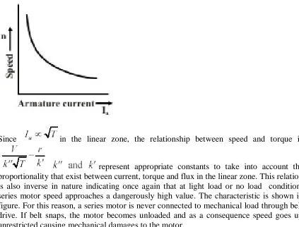
Following the procedure described earlier under shunt motor, the torque speed Characteristics of a series motor can also be determined. The armature current also happens to be the excitation current of the series field and hence the flux variation resembles the magnetization curve of the machine. At large value of the armature currents the useful flux would be less than the no-load magnetization curve for the machine. Similarly for small values of the load currents the torque varies as a square of the armature currents as the flux is proportional to armature current in this region. As the magnetic circuit becomes more and more saturated the torque becomes proportional to Ia as flux variation becomes small.
on series motors to ensure a definite, though small, value of flux even when the armature current is nearly zero. This way the no-load speed is limited to a safe maximum speed. It is needless to say, this field should be connected so as to aid the series field.
Load characteristics of a compound motor
Two situations arise in the case of compound motors. The mmf of the shunt field and series field may oppose each other or they may aid each other. The first configuration is called differential compounding and is rarely used. They lead to unstable operation of the machine unless the armature mmf is small and there is no magnetic saturation. This mode may sometimes result due to the motoring operation of a level-compounded generator, say by the failure of the prime mover. Also, differential compounding may result in large negative mmf under overload/starting condition and the machine may start in the reverse direction. In motors intended for constant speed operation the level of compounding is very low as not to cause any problem.
Cumulatively compounded motors are very widely used for industrial drives.
provided under shunt and series motors for the provision of an additional series/shunt winding, it can be seen that all modern machines are compound machines. The difference between them is only in the level of compounding.
Braking the d.c. Motors
When a motor is switched off it `coasts' to rest under the action of frictional forces.
Braking is employed when rapid stopping is required. In many cases mechanical braking is adopted. The electric braking may be done for various reasons such as those mentioned below:
1. To augment the brake power of the mechanical brakes. 2. To save the life of the mechanical brakes.
3. To regenerate the electrical power and improve the energy efficiency. 4. In the case of emergencies to step the machine instantly.
5. To improve the throughput in many production processes by reducing the stopping time.
In many cases electric braking makes more brake power available to the braking process where mechanical brakes are applied. This reduces the wear and tear of the mechanical brakes and reduces the frequency of the replacement of these parts. By recovering the mechanical energy stored in the rotating parts and pumping it into the supply lines the overall energy efficiency is improved. This is called regeneration. Where the safety of the personnel or the equipment is at stake the machine may be required to stop instantly.
Extremely large brake power is needed under those conditions. Electric braking can help in these situations also. In processes where frequent starting and stopping is involved the process time requirement can be reduced if braking time is reduced. The reduction of the
1. Dynamic 2. Regenerative
3. Reverse voltage braking or plugging
These are now explained briefly with reference to shunt, series and compound motors. Dynamic braking
Shunt machine
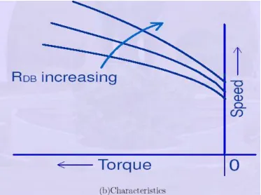
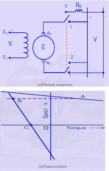
current through the braking resistance. The direction of this current is opposite to the one which was owing before change in the connection. Therefore, torque developed also gets reversed. The machine acts like a brake. The torque speed characteristics separate by excited shunt of the machine under dynamic braking mode is as shown in Fig. (b) for a particular value of RDB. The positive torque corresponds to the motoring operation. Fig. shows the dynamic braking of a shunt excited motor and the corresponding torque-speed curve. Here the machine behaves as a self-excited generator. Below a certain speed the self-excitation collapses and the braking action becomes Zero. Process time improves the throughput.
Basically the electric braking involved is fairly simple. The electric motor can be made to work as a generator by suitable terminal conditions and absorb mechanical energy.
This converted mechanical power is dissipated/used on the electrical network suitably.
Figure : Dynamic braking of shunt excited shunt machine
Series machine
In the case of a series machine the excitation current becomes zero as soon as the armature is disconnected from the mains and hence the induced emf also vanishes. In order to achieve dynamic braking the series field must be isolated and connected to a low voltage high current source to provide the field. Rather, the motor is made to work like a separately excited machine. When several machines are available at any spot, as in railway locomotives, dynamic braking is feasible. Series connection of all the series fields with parallel connection of all the armatures connected across a single dynamic braking resistor is used in that case.
Compound generators
In the case of compound machine, the situation is like in a shunt machine. A separately excited shunt field and the armature connected across the braking resistance are used.
Regenerative braking
In regenerative braking as the name suggests the energy recovered from the rotating masses is fed back into the d.c. power source. Thus this type of braking improves the energy efficiency of the machine. The armature current can be made to reverse for a constant voltage operation by increase in speed/excitation only. Increase in speed does not result in braking and the increase in excitation is feasible only over a small range, which may be of the order of 10 to 15%. Hence the best method for obtaining the regenerative braking is to operate, the machine on a variable voltage supply. As the voltage is continuously pulled below the value of the induced emf the speed steadily comes down. The field current is held constant by means of separate excitation. The variable d.c. supply voltage can be obtained by Ward-Leonard arrangement, shown schematically in Fig. .
Braking torque can be obtained right up to zero speed. In modern times static Ward-Leonard scheme is used for getting the variable d.c. voltage. This has many advantages over its rotating machine counter part. Static set is compact, has higher efficiency, requires lesser space, and silent in operation; however it suffers from drawbacks like large ripple at low voltage levels, unidirectional power flow and low over load capacity. Bidirectional power flow capacity is a must if regenerative braking is required. Series motors cannot be regeneratively braked as the characteristics do not extend to the second quadrant.
Plugging
Plugging also it is necessary to limit the current and thus the torque, to reduce the stress on the mechanical system and the commutator. This is done by adding additional resistance in series with the armature during plugging.
Series motors
In the case of series motors plugging cannot be employed as the field current too gets reversed when reverse voltage is applied across the machine. This keeps the direction of the torque produced unchanged. This fact is used with advantage, in operating a d.c. series motor on d.c. or a.c. supply. Series motors thus qualify to be called as `Universal motors'.
Compound motors
Plugging of compound motors proceeds on similar lines as the shunt motors. However some precautions have to be observed due to the presence of series field winding. A cumulatively compounded motor becomes differentially compounded on plugging. The mmf due to the series field can 'over power' the shunt field forcing the flux to low values or even reverse the net field. This decreases the braking torque, and increases the duration of the large braking current. To avoid this it may be advisable to deactivate the series field at the time of braking by short-circuiting the same. In such cases the braking proceeds just as in a shunt motor. If plugging is done to operate the motor in the negative direction of rotation as well, then the series field has to be reversed and connected for getting the proper mmf. Unlike dynamic braking and regenerative braking where the motor is made to work as a generator during braking period, plugging makes the motor work on reverse motoring mode.
Deducing the machine performance. (Single phase Induction motor)
From the equivalent circuit, many aspects of the steady state behavior of the machine can be deduced. We will begin by looking at the speed-torque characteristic of the machine. We will
Consider the approximate equivalent circuit of the machine. We have reasoned earlier that the power consumed by the 'rotor-portion' of the equivalent circuit is the power transferred across the air-gap. Out of that quantity the amount dissipated in R0 r is the rotor copper loss and the quantity consumed by R0r(1 + s)=s is the mechanical power developed. Neglecting mechanical losses, this is the power available at the shaft. The torque available can be obtained by dividing this number by the shaft speed.
The complete torque-speed characteristic of Induction motor
Where Vs is the phase voltage phasor and Is is the current phasor. The magnetizing current is neglected. Since this current is owing through , the air-gap power is given by
The mechanical power output was shown to be (1_s) Pg (power dissipated in R0r=s). The torque is obtained by dividing this by the shaft speed .Thus we have,
Where! S is the synchronous speed in radians per second and s is the slip. Further, this is the torque produced per phase. Hence the overall torque is given by
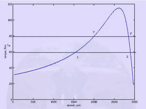
The torque may be plotted as a function of `s' and is called the torque-slip (or torque- speed, since slip indicates speed) characteristic | a very important characteristic of the induction machine. Equation 16 is valid for a two-pole (one pole pair) machine. In general, this expression should be multiplied by p, the number of pole-pairs. A typical torque-speed characteristic is shown in _g. 22. This plot corresponds to a 3 kW, 4 pole,60 Hz machine. The rated operating speed is 1780 rpm.
We must note that the approximate equivalent circuit was used in deriving this relation. Readers with access to MATLAB or suitable equivalents (octave, scilab available free under GNU at the time of this writing) may find out the difference caused by using the `exact' equivalent circuit by using the script found here. A comparison between the two is found in the plot of fig. The plots correspond to a 3 kW, 4 pole, 50 machine, with a rated speed of 1440 rpm. It can be seen that the approximate equivalent circuit is a good approximation in the operating speed range of the machine. Comparing the two figures. We can see that the slope and shape of the characteristics are dependent intimately on the machine parameters.
Torque, Nm to obtain this curve by directly starting the motor with full voltage applied to the terminals and measuring the torque and speed dynamically as it runs up to steady speed.
Another point to note is that the equivalent circuit and the values of torque predicted is valid when the applied voltage waveform is sinusoidal. With non-sinusoidal voltage waveforms, the procedure is not as straightforward.
Restricting ourselves to positive values of slip, we see that the curve has a peak point. This is the maximum torque that the machine can produce, and is called as stalling torque. If the load torque is more than this value, the machine stops rotating or stalls. It occurs at a slip ^s, which for the machine of fig is 0.38. At values of slip lower than ^s, the curve falls steeply down to zero at s = 0. The torque at synchronous speed is therefore zero. At values of slip higher than s = ^s, the curve falls slowly to a minimum value at s = 1. The torque at s = 1 (speed = 0) is called the starting torque.
The value of the stalling torque may be obtained by differentiating the expression for torque with respect to zero and setting it to zero to find the value of ^s. Using this method,
Substituting ^s into the expression for torque gives us the value of the stalling torque ^ T
the negative sign being valid for negative slip.
We may note that if R is chosen equal to becomes unity, which p means that the maximum torque occurs at starting. Thus changing of R r, wherever possible can serve as a means to control the starting torque.
While considering the negative slip range, (generator mode) we note that the maximum torque is higher than in the positive slip region (motoring mode).
Operating Point
Consider a speed torque characteristic shown in fig. For an induction machine, having the load characteristic also superimposed on it. The load is a constant torque load i.e., the torque required for operation is fixed irrespective of speed. The system consisting of the motor and load will operate at a point where the two characteristics meet. From the above plot, we note that there are two such points. We therefore need to find out which of these is the actual operating point.
To answer this we must note that, in practice, the characteristics are never fixed; they change slightly with time. It would be appropriate to consider a small band around the curve drawn where the actual points of the characteristic will lie. This being the case let us considers that the system is operating at point 1, and the load torque demand increases slightly. This is shown in fig, where the change is exaggerated for clarity. This would shift the point of operation to a point 10 at which the slip would be less and the developed torque higher.
The difference in torque-developed 4Te, being positive will accelerate the machine. Any overshoot in speed as it approaches the point 10 will cause it to further accelerate since the developed torque is increasing. Similar arguments may be used to show that if for some reason the developed torque becomes smaller the speed would drop and the effect is cumulative. Therefore we may conclude that 1 is not a stable operating point.
torque, Nm From the foregoing discussions, we can say that the entire region of the speed-torque characteristic from s = 0 to s = ^s is an unstable region, while the region from s = ^s to s = 0 is a stable region. Therefore the machine will always operate between s = 0 and s = ^s.
Modes of Operation
The reader is referred to fig which shows the complete speed-torque characteristic of the induction machine along with the various regions of operation.
curve between
Figure : Stability of operating point
s = 0 and s = 1 is the region where the machine produces torque to rotate a passive load and hence is called the motoring region. Note further that the direction of rotation of the rotor is the same as that of the air gap flux.
Suppose when the rotor is rotating, we change the phase sequence of excitation to the machine. This would cause the rotating stator field to reverse its direction | the rotating stator mmf and the rotor are now moving in opposite directions. If we adopt the convention that positive direction is the direction of the air gap flux, the rotor speed would then be a negative quantity. The slip would be a number greater than unity. Further, the rotor as we know should be "dragged along" by the stator field. Since the rotor is rotating in the opposite direction to that of the field, it would now tend to slow down, and reach zero speed.
Therefore this region (s > 1) is called the braking region. (What would happen if the supply is not cut-off when the speed reaches zero?) . There is yet another situation. Consider a situation where the induction machine is operating from mains and is driving an active load (a load capable of producing rotation by itself). A typical example is that of a windmill, where the fan like blades of the windmill are connected to the shaft of the induction machine. Rotation of the blades may be caused by the motoring action of the machine, or by wind blowing. Further suppose that both acting independently cause rotation in the same direction. Now when both grid and windact, a strong wind may cause the rotor to rotate faster than the mmf produced by the stator excitation. A little reaction shows that slip is then negative.
Braking of d.c shunt motor: basic idea
It is often necessary in many applications to stop a running motor rather quickly. We know that any moving or rotating object acquires kinetic energy. Therefore, how fast we can bring the object to rest will depend essentially upon how quickly we can extract its kinetic energy and make arrangement to dissipate that energy somewhere else. If you stop pedaling your bicycle, it will eventually come to a stop eventually after moving quite some distance. The initial kinetic energy stored, in this case dissipates as heat in the friction of the road. However, to make the stopping faster, brake is applied with the help of rubber brake shoes on the rim of the wheels.
Thus stored K.E now gets two ways of getting dissipated, one at the wheel-brake shoe interface (where most of the energy is dissipated) and the other at the road-tier interface. This is a good method no doubt, but regular maintenance of brake shoes due to wear and tear is necessary.
If a motor is simply disconnected from supply it will eventually come to stop no doubt, but will take longer time particularly for large motors having high rotational inertia. Because here the stored energy has to dissipate mainly through bearing friction and wind friction. The situation can be improved, by forcing the motor to operate as a generator during braking. The idea can be understood remembering that in motor mode electromagnetic torque acts along the direction of rotation while in generator the electromagnetic torque acts in the opposite direction of rotation. Thus by forcing the machine to operate as generator during the braking period, a torque opposite to the direction of rotation will be imposed on the shaft, thereby helping the machine to come to stop quickly. During braking action, the initial K.E stored in the rotor is either dissipated in an external resistance or fed back to the supply or both.
Rheostatic braking
Consider a d.c shunt motor operating from a d.c supply with the switch S connected to position 1 as shown in figure. S is a single pole double throw switch and can be connected either to position 1 or to position 2. One end of an external resistance Rb is connected to position 2 of the switch S as shown.
opposition with the supply voltage. Also note Te and n have same clockwise direction.
Now if S is suddenly thrown to position 2 at t = 0, the armature gets disconnected from the supply and terminated by Rb with field coil remains energized from the supply. Since speed of the rotor can not change instantaneously, the back emf value Eb is still maintained with same polarity prevailing at t = 0-. Thus at t = 0+, armature current will be Ia = Eb/(ra + Rb) and with reversed direction compared to direction prevailing during motor mode at t = 0-.
Obviously for t > 0, the machine is operating as generator dissipating power to Rb and now the electromagnetic torque Te must act in the opposite direction to that of n since Ia has changed direction but has not As time passes after switching, n decreases reducing K.E and as a consequence both Eb and Ia decrease. In other words value of braking torque will be highest at t = 0+, and it decreases progressively and becoming zero when the machine finally
come to a stop.
Plugging or dynamic braking
part of the circuit remains inactive.
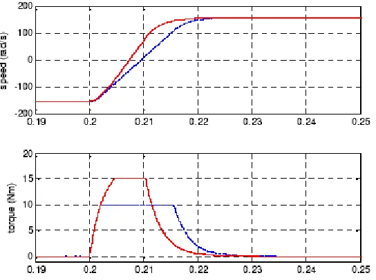
To initiate braking, the switch is thrown to position 2 and 2' at t = 0, thereby disconnecting the armature from the left hand supply. Here at t = 0+, the armature current will be Ia = (Eb + V)/(ra + Rb) as Eb and the right hand supply voltage have additive polarities by virtue of the connection. Here also Ia reverses direction-producing Te in opposite direction to n. Ia decreases as Eb decreases with time as speed decreases. However, Ia can not become zero at any time due to presence of supply V. So unlike rheostatic braking, substantial magnitude of braking torque prevails. Hence stopping of the motor is expected to be much faster then rheostatic breaking.
the reverse direction operating as a motor. So care should be taken to disconnect the right hand supply, the moment armature speed becomes zero.
Regenerative braking
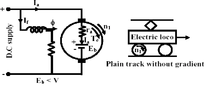
A machine operating as motor may go into regenerative braking mode if its speed becomes sufficiently high so as to make back emf greater than the supply voltage i.e., Eb > V. Obviously under this condition the direction of Ia will reverse imposing torque which is opposite to the direction of rotation. The situation is explained in figures 39.27 and 39.28. The normal motor operation is shown in figure 39.27 where armature motoring current Ia is drawn from the supply and as usual Eb < V. Since The question is how speed on its own become large enough to make Eb < V causing regenerative braking. Such a situation may occur in practice when the mechanical load itself becomes active. Imagine the d.c motor is coupled to the wheel of locomotive which is moving along a plain track without any gradient as shown in figure. Machine is running as a motor at a speed of n1 rpm. However, when the track has a downward gradient (shown in figure 39.28), component of gravitational force along the track also appears which will try to accelerate the motor and may increase its speed to n2 such that Eb In such a scenario, direction of Ia reverses, feeding power back to supply.
UNIT-III
STARTING METHODS
STARTING OF D.C. MACHINES:
For the machine to start, the torque developed by the motor at zero speed must exceed that demanded by the load. Then TM _ TL will be positive so also is di=dt, and the machine accelerates. The induced emf at starting point is zero as the i = 0 The armature current with rated applied voltage is given by V=Ra where Ra is armature circuit resistance.
Normally the armature resistance of a d.c. machine is such as to cause 1 to 5 percent drop at full load current. Hence the starting current tends to rise to several times the full load current. The same can be told of the torque if full flux is already established. The machine instantly picks up the speed. As the speed increases the induced emf appears across the terminals opposing the applied voltage. The current drawn from the mains thus decreases, so also the torque. This continues till the load torque and the motor torque are equal to each other. Machine tends to run continuously at this speed, as the acceleration is zero at this point of operation. The starting is now discussed with respect to specific machines.
If armature and field of d.c. shunt motor are energized together, large current is drawn at start but the torque builds up gradually as the field flux increases gradually. To improve the torque per ampere of line current drawn it is advisable to energize the field first. The starting current is given by V=Ra and hence to reduce the starting current to a safe value, the voltage V can be reduced or armature circuit resistance Ra can be increased. Variable voltage V can be obtained from a motor generator set. This arrangement is called Leonard arrangement. A schematic diagram of Ward-Leonard arrangement is shown in Fig. By controlling the field of the Ward-Ward-Leonard generator one can get a variable voltage at its terminals, which is used, for starting the motor. The second method of starting with increased armature circuit resistance can be obtained by adding additional resistances in series with the armature, at start. The current and the torque get reduced. The torque speed curve under these conditions is shown in Fig. (a). It can be readily seen
from this graph that the unloaded machine reaches its final speed but a loaded machine may crawl at a speed much below the normal speed. Also, the starting resistance wastes large amount of power. Hence the starting resistance must be reduced to zero at the end of the starting process. This has to be done progressively, making sure that the current does not jump up to large values. Starting of series motor and compound motors are similar to the shunt motor. Better starting torques are obtained for compound motors as the torque per ampere is more. Characteristics for series motors are given in fig.
Grading of starting resistance for a shunt motor
If the starting resistor is reduced in uniform steps then the current peaks reached as we cut down the resistances progressively increase. To ascertain that at no step does
Starting of D.C shunt motor
1. Problems of starting with full voltage
We know armature current in a d.c motor is given by
At the instant of starting, rotor speed n = 0, hence starting armature current is
because of fast rise in the back emf. However, for large motor, a starter is to be used during starting.
2. A simple starter
To limit the starting current, a suitable external resistance Rext is connected in series (Figure (a)) with the armature so that At the time of starting, to have sufficient starting torque, field current is maximized by keeping the external field resistance Rf, to zero value. As the motor picks up speed, the value of Rext is gradually decreased to zero so that during running no external resistance remains in the armature circuit. But each time one has to restart the motor, the external armature resistance must be set to maximum value by moving the jockey manually.
Imagine, the motor to be running with Rext = 0 (Figure (b)).
Now if the supply goes off (due to some problem in the supply side or due to load shedding), motor will come to a stop. All on a sudden, let us imagine, supply is restored. This is then nothing but full voltage starting. In other words, one should be constantly alert to set the resistance to maximum value whenever the motor comes to a stop. This is one major limitation of a simple rheostatic starter.
3. 3-point starter
three terminals marked as A, L and F for external connections. Terminal A is connected to one armature terminal Al of the motor. Terminal F is connected to one field terminal F1 of the motor and terminal L is connected to one supply terminal as shown. F2 terminal of field coil is connected to A2 through an external variable field resistance and the common point connected to supply (-ve). The external armatures resistances consist of several resistances connected in series and are shown in the form of an arc. The junctions of the resistances are brought out as terminals (called studs) and marked as 1,2,.. .12. Just beneath the resistances, a continuous copper strip also in the form of an arc is present.
There is a handle which can be moved in the clockwise direction against the spring tension. The spring tension keeps the handle in the OFF position when no one attempts to move it. Now let us trace the circuit from terminal L (supply + ve). The wire from L passes through a small electro magnet called OLRC, (the function of which we shall discuss a little later) and enters through the handle shown by dashed lines. Near the end of the handle two copper strips are firmly connected with the wire. The furthest strip is shown circular shaped and the other strip is shown to be rectangular. When the handle is moved to the right, the circular strip of the handle will make contacts with resistance terminals 1, 2 etc. progressively. On the other hand, the rectangular strip will make contact with the continuous arc copper strip. The other end of this strip is brought as terminal F after going through an electromagnet coil (called NVRC). Terminal F is finally connected to motor field terminal Fl.
Let us explain the operation of the starter. Initially the handle is in the OFF position. Neither armature nor the field of the motor gets supply. Now the handle is moved to stud number 1. In this position armature and all the resistances in series gets connected to the supply. Field coil gets full supply as the rectangular strip makes contact with arc copper strip. As the machine picks up speed handle is moved further r to stud number 2. In this position the external resistance in the armature circuit is less as the first resistance is left out. Field however, continues to get full voltage by virtue of the continuous arc strip. Continuing in this way, all resistances will be left out when stud number 12 (ON) is reached. In this position, the electromagnet (NVRC) will attract the soft iron piece attached to the handle. Even if the operator removes his hand from the handle, it will still remain in the ON position as spring restoring force will be balanced by the force of attraction between NVRC and the soft iron piece of the handle. The no volt release coil (NVRC) carries same current as that of the field coil. In case supply voltage goes off, field coil current will decrease to zero. Hence NVRC will be deenergised and will not be able to exert any force on the soft iron piece of the handle. Restoring force of the spring will bring the handle back in the OFF position.
The starter also provides over load protection for the motor. The other electromagnet, OLRC overload release coil along with a soft iron piece kept under it, is used to achieve this. The current flowing through OLRC is the line current IL drawn by the motor. As the motor is loaded, Ia hence IL increases. Therefore, IL is a measure of loading of the motor. Suppose we want that the motor should not be over loaded beyond rated current. Now gap between the electromagnet and the soft iron piece is so adjusted that for the iron piece will not be pulled up. However, if rated I I force of attraction will be sufficient to pull up iron piece. This upward movement of the iron piece of OLRC is utilized to de-energize NVRC. To the iron a copper strip (Ä shaped in figure) is attached. During over loading condition, this copper strip will also move up and put a short circuit between two terminals B and C. Carefully note that B and C are nothing but the two ends of the NVRC. In other words, when over load occurs a short circuit path is created across the NVRC. Hence NVRC will not carry any current now and gets deenergised. The moment it gets deenergised, spring action will bring the handle in the OFF position thereby disconnecting the motor from the supply.
Three-point starter has one disadvantage. If we want to run the machine at higher speed (above rated speed) by field weakening (i.e., by reducing field current), the strength of NVRC magnet may become so weak that it will fail to hold the handle in the ON position and the spring action will bring it back in the OFF position. Thus we find that a false disconnection of the motor takes place even when there is neither over load nor any sudden disruption of supply.
DIFFERENT TYPES OF STARTERS FOR 3 PHASE INDUCTION
MOTOR (IM)
• Need of using starters for Induction motor
• Two (Star-Delta and Auto-transformer) types of starters used for Squirrel cage Induction motor
• Starter using additional resistance in rotor circuit, for Wound rotor (Slip-ring) Induction motor
Introduction
In the previous, i.e. fourth, lesson of this module, the expression of gross torque developed, as a function of slip (speed), in IM has been derived first. The sketches of the different torque-slip (speed) characteristics, with the variations in input (stator) voltage and rotor resistance, are presented, along with the explanation of their features. Lastly, the expression of maximum torque developed and also the slip, where it occurs, have been derived. In this lesson, starting with the need for using starters in IM to reduce the starting current, first two (Star-Delta and Auto-transformer) types of starters used for Squirrel cage IM and then, the starter using additional resistance in rotor circuit, for Wound rotor (Slip-ring) IM, are presented along with the starting current drawn from the input (supply) voltage, and also the starting torque developed using the above starters. Keywords:
Direct-on-Line (DOL) starter, Star-delta starter, auto-transformer starter, rotor resistance starter, starting current, starting torque, starters for squirrel cage and wound rotor induction motor, need for starters.
Direct-on-Line (DOL) Starters
The input voltage per phase to the stator is equal to the induced emf per phase in the stator winding, as the stator impedance is neglected (also shown in the last lesson (#32)). In the formula for starting current, no load current is neglected. It may be noted that the starting current is quite high, about 4-6 times the current at full load, may be higher, depending on the rating of IM, as compared to no load current. The starting torque is which shows that, as the starting current increases, the starting torque also increases. This results in higher accelerating torque (minus the load torque and the torque component of the losses), with the motor reaching rated or near rated speed quickly.
The main problem in starting induction motors having large or medium size lies mainly in the requirement of high starting current, when started direct-on-line (DOL). Assume that the distribution line is starting from a substation (Fig.), where the supply voltage is constant. The line feeds a no. of consumers, of which one consumer has an induction motor with a DOL starter, drawing a high current from the line, which is higher than the current for which this line is designed. This will cause a drop (dip) in the voltage, all along the line, both for the consumers between the substation and this consumer, and those, who are in the line after this consumer. This drop in the voltage is more than the drop permitted, i.e. higher than the limit as per ISS, because the current drawn is more than the current for which the line is designed. Only for the current lower the current for which the line is designed, the drop in voltage is lower the limit. So, the supply authorities set a limit on the rating or size of IM, which can be started DOL. Any motor exceeding the specified rating, is not permitted to be started DOL, for which a starter is to be used to reduce the current drawn at starting.
Starters for Cage IM
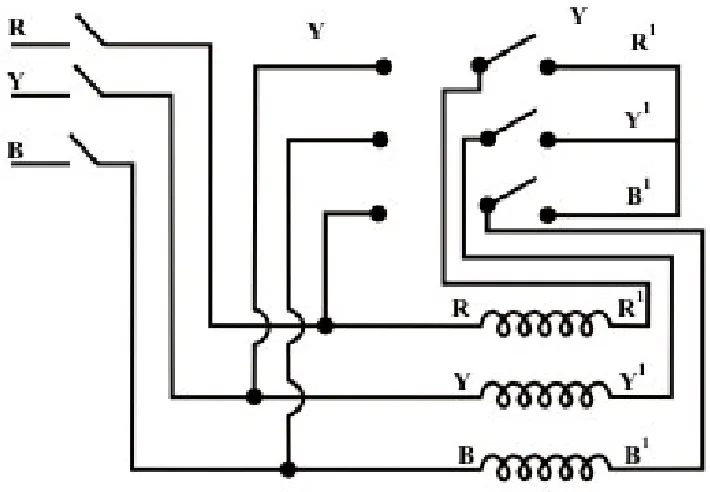
This type is used for the induction motor, the stator winding of which is nominally delta-connected (Fig. 33.2a). If the above winding is reconnected as star (Fig. 33.2b), the voltage per phase supplied to each winding is reduced by )1/3(.577). This is a simple starter, which can be easily reconfigured as shown in Fig. 33.2c. As the voltage per phase in delta connection is Vs, the phase current in each stator winding is
An auto-transformer, whose output is fed to the stator and input is from the supply (Fig. 33.3), is used to start the induction motor. The input voltage of IM is , which is the output voltage of the auto-transformer, the input voltage being Vs. The output
voltage/input voltage ratio is x , the value of which lies between 0.0 and 1.0 Let be the starting current, when the motor is started using DOL starter, i.e applying rated input voltage. The input current of IM, which is the output current of auto-transformer, when this starter is used with input voltage as . The input current of auto-transformer, which is the starting current drawn from the supply, is, obtained by equating input and output volt-amperes, neglecting losses and assuming nearly same power factor on both sides. As discussed earlier, the starting torque, being proportional to the square of the input current to IM in two cases, with and without auto-transformer (i.e. direct), is also reduced by , as the ratio of the two currents is same as that (ratio) of the voltages applied to the motor as shown earlier. So, the starting torque is reduced by the same ratio as that of the starting current.
Rotor Resistance Starters for Slip-ring (wound rotor) IM
In a slip-ring (wound rotor) induction motor, resistance can be inserted in the rotor circuit via slip rings (Fig. 33.4), so as to increase the starting torque. The starting current in the rotor winding is
where = Additional resistance per phase in the rotor circuit.
The input (stator) current is proportional to the rotor current as shown earlier. The starting current (input) reduces, as resistance is inserted in the rotor circuit. But the
starting torque increases, as the total resistance in
start IM with high load torque. It may be observed from Fig. 32.2b that the starting torque increases till it reaches maximum value, the external resistance in the rotor circuit is increased, the range of total resistance being The range of external resistance is between zero (0.0) and 2 r x -). The starting torque is equal to the maximum value, i.e. if the external resistance inserted is equal to if the external resistance in the rotor circuit is increased further, the starting torque decreases. This is, because the This is, because the starting current decreases at a faster rate, even if the total resistance in the rotor circuit is increased.
In this lesson - the fifth one of this module, the direct-on-line (DOL) starter used for IM, along with the need for other types of starters, has been described first. Then, two types of starters - star-delta and autotransformer, for cage type IM, are presented. Lastly, the rotor resistance starter for slip-ring (wound rotor) IM is briefly described. In the next (sixth and last) lesson of this module, the various types of single-phase induction motors, along with the starting methods, will be presented.
STARTING METHODS FOR SINGLE-PHASE INDUCTION MOTOR
Instructional Objectives
• Why there is no starting torque in a single-phase induction motor with one (main) winding in the stator?
• Various starting methods used in the single-phase induction motors, with the introduction of additional features, like the addition of another winding in the stator, and/or capacitor in series with it.
Introduction
firstly it is shown that there is no starting torque in a single-phase induction motor with only one (main) winding in the stator. Then, the various starting methods used for such motors, like, say, the addition of another (auxiliary) winding in the stator, and/or capacitor in series with it.
Keywords:
Single-phase induction motor, starting torque, main and auxiliary windings, starting methods, split-phase, capacitor type, motor with capacitor start/run.
Single-phase Induction Motor
The winding used normally in the stator (Fig.) of the single-phase induction motor (IM) is a distributed one. The rotor is of squirrel cage type, which is a cheap one, as the rating of this type of motor is low, unlike that for a three-phase IM. As the stator winding is fed from a single-three-phase supply, the flux in the air gap is alternating only, not a synchronously rotating one produced by a poly-phase (may be two- or three-) winding in the stator of IM. This type of alternating field cannot produce a torque if the rotor is stationery
so, a single-phase IM is not self-starting, unlike a
three-phase one. However, as shown later, if the rotor is initially given some
torque in either direction then immediately a torque is produced in the motor. The motor then accelerates to its final speed, which is lower than its synchronous speed. This is now explained using double field revolving theory.
When the stator winding (distributed one as stated earlier) carries a sinusoidal current (being fed from a single-phase supply), a sinusoidal space distributed mmf, whose peak or maximum value pulsates (alternates) with time,
is produced in the air gap. This sinusoidally varying flux is the sum of two rotating fluxes or fields, the magnitude of which is equal to half the value of the
alternating flux and both the fluxes rotating synchronously at the speed,
The flux or field rotating at synchronous speed, say, in the anticlockwise direction, i.e. the same direction, as that of the motor (rotor) taken as positive induces emf (voltage) in the rotor conductors. The rotor is a squirrel cage one, with bars short circuited via end rings. The current flows in the rotor conductors, and the electromagnetic torque is produced in the same direction as given above, which is termed as positive (+ve). The other part of flux or field rotates at the same speed in the opposite (clockwise) direction, taken as negative. So, the torque produced by this field is negative (-ve), as it is in the clockwise direction, same as that of the direction of rotation of this field. Two torques are in the opposite direction, and the resultant (total) torque is the difference of the two
torques produced (Fig. 34.3). If the rotor is stationary the slip due to forward (anticlockwise) rotating field is 0 . 1 = sf . Similarly, the slip due to
backward rotating field is also sb = 0 .1. The two torques are equal and opposite,
and the resultant torque is 0.0 (zero). So, there is no starting torque in a single-phase IM.
But, if the motor (rotor) is started or rotated somehow, say in the anticlockwise (forward) direction, the forward torque is more than the backward torque, with the resultant torque now being positive. The motor accelerates in the forward direction, with the forward torque being more than the backward torque. The resultant torque is thus positive as the motor rotates in the forward direction. The motor speed is decided by the load torque supplied, including the losses (specially mechanical loss).
Mathematically, the mmf, which is distributed sinusoidally in space, with its
angle) measured from the winding axis. Now, So, the mmf
is distributed both in space and time, i.e. This can be expressed as,
which shows that a pulsating field can be considered as the sum of two
synchronously rotating fields The forward rotating field is,
and the backward rotating field is,
Both the fields have the same amplitude equal to
where is the maximum value of the pulsating mmf along the axis of the winding. When the motor rotates in the forward (anticlockwise) direction
with angular speed the slip due to the forward rotating field is,
Similarly, the slip
due to the backward rotating field, the speed of which is is,
The torques produced by the two fields are in opposite direction.
The resultant torque is,
It was earlier shown that, when the rotor is stationary,
with both as Therefore, the
resultant torque at start is 0.0 (zero).
STARTING METHODS
of 90 , to produce maximum starting torque, as shown in a balanced two-phase stator. Thus, rotating magnetic field is produced in such motor, giving rise to starting torque. The various starting methods used in a single-phase IM are described here.
Resistance Split-phase Motor
The schematic (circuit) diagram of this motor is given in Fig. . As detailed earlier, another (auxiliary) winding with a high resistance in series is to be added along with the main winding in the stator. This winding has higher resistance to
reactance ratio as compared to that in the main winding, and is
placed at a space angle of from the main winding as given earlier. The phasor diagram of the currents in two windings and the input voltage is shown in Fig. 34.4b. The current (Ia ) in the auxiliary winding lags the voltage (V ) by an
angle, which is small, whereas the current (Im ) in the main winding lags the
voltage (V ) by an angle, which is nearly 90o. The phase angle between the
full load current. The torque-speed characteristics of the motor with/without auxiliary winding are shown in Fig. The change over occurs, when the auxiliary winding is switched off as given earlier. The direction of rotation is reversed by reversing the terminals of any one of two windings, but not both, before connecting the motor to the supply terminals. This motor is used in applications, such as fan, saw, small lathe, centrifugal pump, blower, office equipment, washing machine, etc.
The motor described earlier, is a simple one, requiring only second (auxiliary) winding placed at a space angle of 90o from the main winding, which is there in nearly all such motors as discussed here. It does not need any other thing, except for centrifugal switch, as the auxiliary winding is used as a starting winding. But the main problem is low starting torque in the motor, as this torque is a function of, or related to the phase difference (angle) between the currents in the two windings. To get high starting torque, the phase difference required is 90°(Fig. 34.5b), when the starting torque will be proportional to the product of the
magnitudes of two currents. As the current in the main winding is lagging by
the current in the auxiliary winding has to lead the input voltage by with
is taken as negative (-ve), while is positive (+ve). This can be can be achieved by having a capacitor in series with the auxiliary winding, which results in additional cost, with the increase in starting torque,
The two types of such motors are described here.
The schematic (circuit) diagram of this motor is given in Fig. It may be observed that a capacitor along with a centrifugal switch is connected in series with the auxiliary winding, which is being used here as a starting winding. The capacitor may be rated only for intermittent duty, the cost of which decreases, as it is used only at the time of starting.
The function of the centrifugal switch has been described earlier. The phasor diagram of two currents as described earlier, and the torque-speed characteristics of the motor with/without auxiliary winding, are shown in Fig. respectively. This motor is used in applications, such as compressor, conveyor, machine tool drive, refrigeration and air-conditioning equipment, etc.
In this motor (Fig. 34.6a), two capacitors -Cs for starting, and Cr for running, are
Beside the above two types of motors, a Permanent Capacitor Motor (Fig.) with the same capacitor being utilised for both starting and running, is also used. The power factor of this motor, when it is operating (running), is high. The operation is also quiet and smooth. This motor is used in applications, such as ceiling fans, air circulator, blower, etc.
Shaded-pole Motor
A typical shaded-pole motor with a cage rotor is shown in Fig. This is a singlephase induction motor, with main winding in the stator. A small portion of each pole is covered with a short-circuited, single-turn copper coil called the shading coil. The sinusoidally varying flux created by ac (single-phase) excitation of the main winding induces emf in the shading coil. As a result, induced currents flow in the shading coil producing their own flux in the shaded portion of the pole.
As per the above equations, the shading coil current (Isc ) and flux
phasors lag behind the induced emf (Esc ) by angle while the flux
phasor leads the induced emf (Esc ) by 90o. Obviously the phasor is in phase
with The resultant flux in the shaded pole is given by the phasor
sum as shown in Fig. and lags the flux of the remaining pole
by the angle The two sinusoidally varying fluxes are displaced in space as well as have a time phase difference thereby producing forward and backward rotating fields, which produce a net torque. It may be noted that the motor is self-starting unlike a single-phase single-winding motor. It is seen from the phasor diagram (Fig. 34.8b) that the net flux in the shaded portion of the
In this lesson - the sixth and last one of this module, firstly, it is shown that, no starting torque is produced in the single-phase induction motor with only one (main) stator winding, as the flux produced is a pulsating one, with the winding being fed from single phase supply. Using double revolving field theory, the torque-speed characteristics
of this type of motor are described, and it is also shown that, if the motor is initially given some torque in either direction, the motor accelerates in that direction, and also the torque is produced in that direction. Then, the various types of single-phase induction motors, along with the starting methods used in each one are presented.
UNIT-IV
CONVENTIONAL AND SOLID STATE SPEED CONTROL OF D.C. DRIVES
SPEED CONTROL OF D.C. MOTORS:
In the case of speed control, armature voltage control and flux control methods are available. The voltage control can be from a variable voltage source like Ward-Leonard arrangement or by the use of series armature resistance. Unlike the starting conditions the series resistance has to be in the circuit throughout in the case of speed control. That means considerable energy is lost in these resistors. Further these resistors must be adequately cooled for continuous operation. The variable voltage source on the other hand gives the motor the voltage just needed by it and the losses in the control gear is a minimum. This method is commonly used when the speed ratio required is large, as also the power rating.
Field control or flux control is also used for speed control purposes. Normally field weakening is used. This causes operation at higher speeds than the nominal speed. Strengthening the field has little scope for speed control as the machines are already in a state of saturation and large field mmf is needed for small increase in the flux. Even though flux weakening gives higher speeds of operation it reduces the torque produced by the machine for a given armature current and hence the power delivered does not increase at any armature current. The machine is said to be in constant power mode under field weakening mode of control. Above the nominal speed of operation, constant ux mode with increased applied voltage can be used; but this is never done as the stress on the commutator insulation increases.
Thus operation below nominal speed is done by voltage control. Above the nominal speed field weakening is adopted. For weakening the field, series resistances are used for shunt as well as compound motors. In the case of series motors however field weakening is done by the use of „diverters‟. Diverters are resistances that are connected in parallel to the series winding to reduce the field current without affecting the armature current.
Speed control of shunt motor
We know that the speed of shunt motor is given by:
1. Speed control by varying armature resistance
The inherent armature resistance ra being small, speed n versus armature current Ia characteristic will be a straight line with a small negative slope as shown in figure . In the discussion to follow we shall not disturb the field current from its rated value. At no load (i.e., Ia = 0) speed is highest and Note that for shunt motor voltage applied to the field and armature circuit are same and equal to the supply voltage V. However, as the motor is loaded, Iara drop increases making speed a little less than the no load speed n0. For a well-designed shunt motor this drop in speed is small and about 3 to 5% with respect to no load speed. This drop in speed from no load to full load condition expressed as a percentage of no load speed is called the inherent speed regulation of the motor.
It is for this reason, a d.c shunt motor is said to be practically a constant speed motor (with no external armature resistance connected) since speed drops by a small amount from no load to full load condition.
Since for constant operation, Te becomes simply proportional to Ia. Therefore, speed vs. torque characteristic is also similar to speed vs. armature current characteristic as shown in figure.
vs. armature curves as shown in figures for various values of rext. From these characteristics it can be explained how