Validation of EGY-DRIP program in determining the
optimum lateral length
Hisham Mohamed Imam
1*, Sabreen Khalil Pibars
2(1. Department of Field Irrigation and Drainage Engineering Researches, Agricultural Engineering Research Institute, Giza, Egypt; 2. Water Relation and Field Irrigation Department, Agricultural Division, National Research Centre, El-Dokki, Cairo, Egypt.)
Abstract: In drip irrigation systems the lateral lines are the pipes on which the emitters are installed. The accurate design of drip irrigation laterals needs to determine the total energy losses that include the pipe friction losses along the lateral line and minor losses due to emitter connections. A friendly user interface computer program named EGY-DRIP had developed for drip irrigation system design. The program had written in Microsoft visual basic 2013 to carry out hydraulic calculations of drip irrigation sub-unit design. The hydraulic calculation based on inputs of water properties, quality, soil characteristics, reference evapotranspiration, crop parameters, and irrigation system components (drippers, pipes, and fittings). The program supported with an upgradable Microsoft access database to facilitate data input by the user. The program determines the optimum lateral length applying two mathematical models developed using dimensional analysis. An experimental drip irrigation sub-unit was used to make a field evaluation of EGY-DRIP to determine the optimum lateral length for built-in and on-line emitters. The lateral length was determined on the base on 10% variation in the emitters’ discharge, 50% friction head losses limit for manifold and 50% for the laterals. There was a good agreement between the field measured and the calculated optimum lateral length using EGY-DRIP program. The average difference between the measured and the calculated length was 0.5 m for built-in emitters and 0.58 m for the on-line emitters.
Keywords: validation, drip irrigation system, EGY-DRIP program, friction losses
Citation: Imam, H. M., and S. Kh. Pibar. 2019. Validation of EGY-DRIP program in determining the optimum lateral length.
Agricultural Engineering International: CIGR Journal, 21(4): 14–23.
1 Introduction
Drip irrigation is one of the impotent modern techniques in irrigation systems which saves water, consumes low energy, improves the on-farm water management, and increases crop yield productivity. A typical drip irrigation system consists of the control head, main and sub-main lines, manifold, laterals, emitters, flow controls, and flow pressure regulators. For optimum design, the field divided into sub-units to reduce both pipelines diameters and lengths which in turn reduce the friction head losses, capital costs and to achieve better control of drip irrigation system.
Received date: 2019-02-17 Accepted date: 2019-06-30 * Corresponding author: Hisham Mohamed Imam, Researcher.
Department of Field Irrigation and Drainage Engineering Researches, Agricultural Engineering Research Institute, Egypt. Email: [email protected]. Tel: +2011154333696.
Many considerations, which must be taken into account in the design of drip irrigation system, including field topography, soil type, crop to be grown, weather conditions, availability of labor, energy, available technology and financial resources. Attempts to quantify these parameters for designing drip irrigation systems resulted in a very cumbersome and time consuming task (Patel and Rajput, 2004). The use of computers removes much tedious work associated with repetitive complex calculations and manipulation of large pools of data. These results are in less error frequency and more detailed analysis when compared to non-computer aided design (Ismail et al.,2001).
2012). Some of these computer models exceeded to calculate pressure drop, flow rate and distribution uniformity of system pipelines network (manifold, sub-main and main lines) to find the economically optimum pipe size (Sharaf and Hassan, 2006; Zella et al., 2006; Ghaemi and Tabarzad, 2014). The design of a sub-unit was also considered in computer models through both size and shape of the irrigated area (Sharaf and Hassan, 2006; Mahrous et al., 2008; and Nina et al., 2012).
Model computations are supported by a database containing updated data of the micro-irrigation system components. Another database of crop properties, some Egyptian climatic zones and soil physical properties were utilized in designing computer models (Ismail et al., 2001).
Most of these developed models didn’t concern the effect of the geometric parameters of emitters, soil physical properties, and irrigation water requirement on the determination of optimum length of lateral subsequently the dimensions and water distribution uniformity of sub-unit.
The objective is to evaluate the lateral length determination using EGY-DRIP computer program and to compare the simulated results with the on-farm measurements. EGY-DRIP program carries out hydraulic calculations taking into account data of water properties, the soil physical properties, the irrigation water requirement, and emitters geometrical parameters to determine the optimum length of the lateral and dimension of sub-unit.
2 Material and methods
The optimum lateral length determined by calculating the accumulated friction head losses between two adjacent emitters along the lateral line that variation in emitters discharge should not exceed 10%. The spacing between emitters in the row should not exceed 80% of the wetted diameter, which depends on the hydraulic conductivity of the soil, the emitter discharge, and on the total amount of water in the soil. It is useful to limit the lateral pressure head difference to 50% of the sub-unit pressure head variation and the other 50% to occur within the manifold (Keller and Bliesner, 1990).
Wetted area:
Schwartzmass and Zur (1985) developed a general empirical equation to estimate the wetted depth and width (Keller and Bliesner, 1990):
w=0.0094(z)0.35(q)0.33(ks)-0.33 (1)
where, w = wetted width or diameter of water pattern, (m); z = vertical distance to wetting front, (m); q = point-source emitter discharge, (L h-1); ks = saturated
hydraulic conductivity of the soil, (m s-1).
Emitter spacing:
Emitters might be placed on laterals to have an overlapping between adjacent wetted circles. The distance between two adjacent emitters is:
L=0.8w (2)
where, L = distance between two adjacent emitters, (m).
Emitter equation:
The relationship between emitter water discharge (qe)
and operating pressure head (he) is (Clark et al., 2007):
x e e e
q =k h (3)
where, ke = Emitter discharge coefficient; x = Emitter
discharge exponent; qe = Emitter discharge (L h-1); he =
Operating pressure head (m).
The allowable friction head losses difference:
The allowable difference in friction head losses of a sub-unit can be estimated using the following relation (Ismail et al., 2001).
Δ
Δ av
q
H x h
q
⎛ ⎞
= ⎜ ⎟×
⎝ ⎠ (4)
where, ∆H = allowable difference in friction head losses of a sub-unit (m); q = emitter discharge (L h-1); ∆q = allowable difference in emitter discharge (L h-1); hav =
average operating pressure head of a sub-unit (m).
Friction head losses model for lateral pipe with on-line
and built-in emitters:
Two mathematical models were developed to predict the friction head losses between two adjacent emitters on lateral line equipped with both on-line and built-in emitters. The parameters affecting the friction head losses in lateral defined in dimensionless terms using Buckingham’s Π theorem (Imam et al., 2015).
The predicting model of friction head losses in lateral line with on-line emitters is:
The predicting model of friction head losses with built-in emitters is:
∆H=5.741ρ-0.266μ0.266g-1v1.734D0.936L0.141De-1.158Le-0.185 (6)
where, ΔH = Friction head losses in emitter spacing (m);
ρ = Water density (kg m-3); μ = Water viscosity (kg ms-3);
v = Average velocity (m s-1); D = Inner diameter of the pipe (m); L = Emitter spacing (m); . (m2); Ae = Barb
protrusion area (m2); De = Emitter inside diameter (m);
Le = Emitter length (m).
Determination of lateral length:
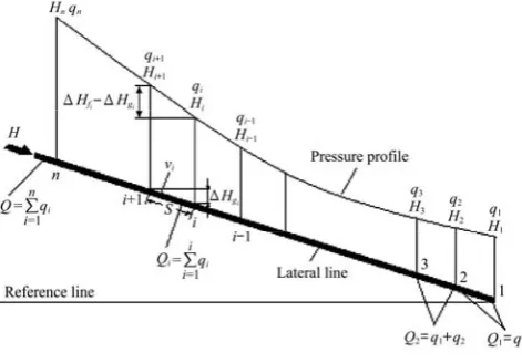
Drip irrigation laterals are not only smooths pipes, but also have multiple outlets depending upon the emitter type and spacing. Since emitters discharge water along the lateral line, the total flow rate decreases and the pressure changes in the lateral line with respect to the length. For this reason, pressure and flow rate relations are considered in order to determine the optimum lateral lengths and water distribution uniformity from the emitters along the lateral Figure 1 (Yurdem et al., 2011). Starting from the far-end emitter, with the minimum desired discharge, moving against water direction, friction losses are calculated for each segment depending on the passing flow, which increases in the opposite flow direction (Alazba and El-Nesr, 2011).
Figure 1 The pressure and flow rate distribution along the drip irrigation lateral line (Yurdem et al., 2011)
The inlet pressure head at every emitter expressed as (Yurdem et al., 2011):
Hi=Hi–1+∆Hf ±∆Hg (7)
where, Hi = inlet pressure in ith emitter (m); Hi–1 = inlet
pressure in emitter i–1 (m); ∆Hf = friction loss between
emitter i and emitter i–1 (m); ∆Hg = elevation between
emitter i and emitter i–1 (m).
EGY-DRIP program:
EGY-DRIP is a friendly user interface computer program developed to determine the optimum length of the lateral and the dimension of the sub-unit to achieve a high distribution uniformity of irrigation water. The program was written in Microsoft visual basic 2013. EGY-DRIP program carries out hydraulic calculations taking into account data on the soil physical properties, the irrigation water requirement, and emitters geometrical parameters.
The program uses both field and technical data to perform the hydraulic calculations. The user starts by entering field data about, water source and quality, soil characteristics, reference evapotranspiration, and planted crops. They needed technical data are specifications of drippers, distribution piping system and fittings. The program calculates the irrigation water requirements, number of drippers per plant, distance between drippers, optimum lateral length, and pressure head losses of manifold pipeline.
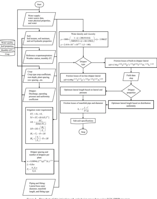
EGY-DRIP provided with a database for water quality, crops, reference evapotranspiration, and soil characteristics to facilitate input of data input by the user. The flow chart of the program is outlined in Figure 2.
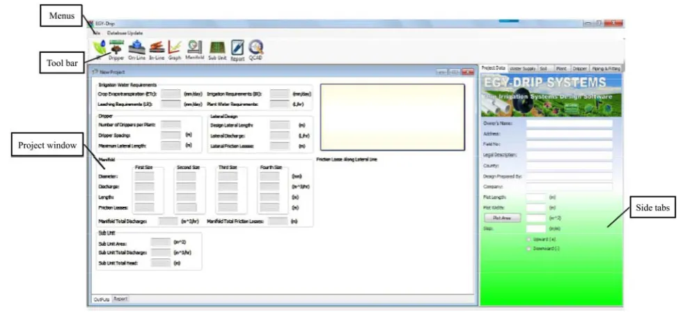
EGY-DRIP program window are shown in Figure 3 which is contained:
Menus:
There are only two pull down menus. File menu contains the basic functions of windows software like Open, Save, Print and Exit. The Database Update menu shows the database table to be updated.
Side Tabs:
The tab control designed to be a platform for data input that is needed for the design process and hydraulic calculations. It contains tab pages of Project Data, Water Supply, Soil, Plant, Dripper, and Piping and Fitting.
Tool Bar:
It contains buttons which trigger the calculation steps like irrigation water requirements, number of drippers, lateral and manifold friction losses. There is a button to present a printable form of the program outputs detailed report.
Project window:
report tab page. The outputs tab page displays the results which are irrigation water requirements, dripper spacing, lateral design, manifold (length, telescopic diameters and friction losses) and sub-unit specifications. A graph area
was set aside to display the friction losses variation along the lateral length. The report tab page presents a printable copy of all project details and it can also be saved as text file.
Figure 3 The main window of EGY-DRIP program
Soil
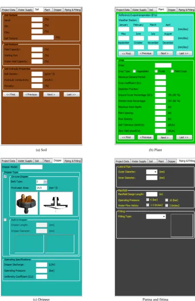
The spacing between emitters in the row should not exceed 80% of the wetted diameter to have a continuous wetted strip. The area wetted by each emitter, depends on the hydraulic conductivity of the soil, the emitter discharge, and on the total amount of water in the soil (Keller and Bliesner, 1990; Ismail et al., 2001). Soil characteristics like soil texture, moisture content and hydraulic conductivity are inputted through soil tab page shown in Figure 4(a).
Plant
Reference evapotranspiration and crop characteristics can be entered through plant tab page Figure 4(b), which are parameters essential for irrigation water requirements calculations and determination of emitters number.
Dripper
Dripper tab page in Figure 4(c) contains the geometric and operating specifications of both on-line and built-in drippers, which is essential in friction losses and lateral optimum length determination. The user should select the dripper type to activate its group box. The on-line dripper group box provided with a number of barb protrusion areas of the conventionally used dripper. The built-in dripper geometrical data have to be added according to the manufacturer specifications.
Piping and Fitting
Other geometrical and technical parameters which are needed for discharge and friction losses calculations of the laterals, manifold can be entered through piping and fitting tab page Figure 4(d). It contains text boxes for
manifold length, hose pipe diameter, fitting type, and operating pressure.
Field evaluation:
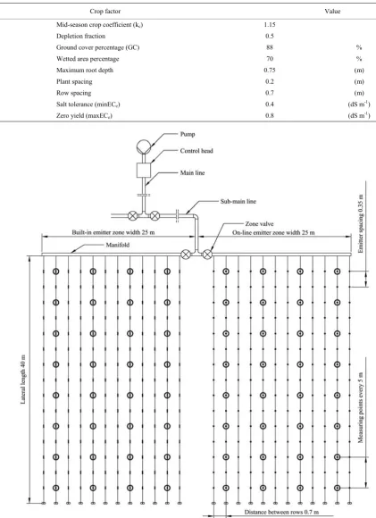
The field evaluation of EYG-Drip program was carried out in the experimental farm of National Research Centre (NRC), El-Nubaria, Beheira Governorate, Egypt. The soil texture physical properties analyses are shown in Table 1. The planted crop was Peanut (Arachishypogaea L.) cultivar Giza-6, in summer growing season of 2017 and the crop characteristics are listed in Table 2.
The planted crop was irrigated using an experimental sub-unit of 40×50 m size. The manifold line was a PVC pipe of 32 mm diameter – 6 bar with 50 m long. It was branched according to emitter type into two zones with 25 m manifold long and every branch controlled by a ball valve. Lateral lines were a 16 mm diameter PE tube with 40 m long. For every emitter type zone, it was divided into four longitudinal quarters, a lateral line was selected at every zonal quarter to determine the pressure drop along it, and the measuring point was selected at every 5 meters along the lateral line to measure pressure value and emitter discharge. A schematic plan of measurement points for each emitter type, emitter spacing, and selected laterals are shown in Figure 5. Two types of emitters were used in the evaluation: built-in cylindrical emitter and on-line emitters shown in
(a) Soil (b) Plant
(c) Dripper Piping and fitting Figure 4 EGY-DRIP program data input tabs
Table 1 The soil physical properties and mechanical analysis of the experimental site
Physical properties Mechanical analysis,% Depth
(cm)
SP (%) θFc(%) θwp(%) A.W(%) BD (g cm-1) HC (c h-1) Course sand Fine sand Clay + Silt Texture
0-20 21 10.1 4.7 5.4 1.69 22.5 47.76 49.75 2.49 20-40 19 13.5 5.6 7.9 1.69 19 56.72 39.56 3.72
40-60 22 12.5 4.6 7.9 1.67 21 36.76 59.4 3.84
Sandy
Table 2 Crop parameters of Peanut (Arachishypogaea L.) cultivar Giza-6
Crop factor Value
Mid-season crop coefficient (kc) 1.15
Depletion fraction 0.5
Ground cover percentage (GC) 88 %
Wetted area percentage 70 %
Maximum root depth 0.75 (m)
Plant spacing 0.2 (m)
Row spacing 0.7 (m)
Salt tolerance (minECe) 0.4 (dS m-1)
Zero yield (maxECe) 0.8 (dS m-1)
Figure 5 A schematic plan of measurement points for each emitter type, emitter spacing, and selected laterals
Table 3 Geometric and hydraulic specifications of both built-in and on-line emitters
Specifications Built-in Emitter On-line Emitter Emitter length (Le) 35 mm
Emitter diameter (De) 12 mm
(Ae) 13 mm2
Emitter discharge exponent (x) 0.537 0.548 Emitter discharge coefficient (ke) 3.624 3.775
Emitter Coefficient variation (CV) 6.9% 5.7%
3 Results and discussion
Results:
The pressure drop along lateral lines of the experimental drip irrigation sub-unit was measured for both the built-in and on-line emitter types. The measured pressure drop and the discharge of the two emitter types are presented in Tables 4 and 5.
Table 4 The on-field measurements of pressure drop and discharges of the built-in emitters along the selected laterals
1st Lateral 2nd Lateral 3rd Lateral 4th Lateral
P (bar) Q (L h-1) P (bar) Q (L h-1) P (bar) Q (L h-1) P (bar) Q (L h-1)
0.97 3.912 0.97 3.9 0.96 3.804 0.95 3.648 0.97 3.888 0.97 3.912 0.95 3.72 0.94 3.6 0.97 3.864 0.97 3.84 0.95 3.696 0.94 3.612 0.97 3.84 0.97 3.816 0.94 3.6 0.92 3.492 0.97 3.852 0.96 3.78 0.94 3.564 0.92 3.444 0.96 3.732 0.96 3.72 0.91 3.48 0.91 3.324 0.96 3.708 0.94 3.624 0.9 3.456 0.9 3.276 0.92 3.468 0.9 3.384 0.86 3.3 0.84 3.18 0.88 3.384 0.86 3.288 0.82 3.24 0.81 3.12
Table 5 The on-field measurements of pressure drop and discharges of the on-line emitters along the selected laterals
1st Lateral 2nd Lateral 3rd Lateral 4th Lateral
P (bar) Q (L h-1) P (bar) Q (L h-1) P (bar) Q (L h-1) P (bar) Q (L h-1)
1.00 4.013 0.99 3.973 0.98 3.952 0.96 3.920 0.99 3.973 0.99 3.973 0.98 3.910 0.95 3.874 0.99 3.973 0.98 3.934 0.97 3.894 0.94 3.775 0.99 3.973 0.97 3.894 0.96 3.854 0.94 3.775 0.96 3.854 0.96 3.854 0.95 3.814 0.93 3.735 0.94 3.775 0.94 3.775 0.93 3.735 0.90 3.615 0.93 3.735 0.92 3.695 0.92 3.695 0.86 3.456 0.91 3.655 0.91 3.655 0.90 3.615 0.84 3.327 0.89 3.576 0.88 3.536 0.87 3.496 0.82 3.287
Data of water properties, soil characteristics, reference evapotranspiration Eto, planted peanut crop
parameters and the geometric dimensions of both built-in and on-line emitters were inputted to the EGY-DRIP program. The program determined the water density (ρ) and viscosity (μ) through the water temperature. Both reference evapotranspiration Eto and, planted peanut crop
parameters were used to calculate the needed emitter discharge (q). To find the emitter spacing (L), the program calculated wetted diameter which depends on saturated hydraulic conductivity of the soil and emitter discharge. The geometric dimensions ofbuilt-in were both the emitter length (Le) and inside diameter (De), where it was
barb protrusion area (Ae) for on-line. The computer
program calculated the expected friction head losses along the lateral line and the optimum lateral length by applying the mathematical models (5) and (6). The calculated optimum lateral lengths based on 10% variation in emitter discharge and 50% limit of pressure head losses for lateral. The calculated optimum lateral lengths using EGY-DRIP program were: 41, 41, 37, and 43 m for the built-in emitter and it was 36.25 m for the on-line emitters.
It can be noted form the on-field measured data in Tables 4 and 5 the measured optimum lateral lengths were: 40, 40, 38, and 38 m for the built-in emitters and 37.5, 37, 36, and 36 m for on-line emitters.
The statistical analysis showed no significant difference between the calculated and the measured lateral lengths for both built-in and on-line emitters. The f-ratio value is 0.157895 and P-value was 0.704853 as listed in Table 6. The result was not significant at P<0.05 for the built-in emitter lateral length.
Table 6 ANOVA results of variation between the on-field
measured and the calculated optimum lateral length by
EGY-DRIP for built-in emitters
Source of Variation SS df MS F P-value F crit Between Groups 0.5 1 0.5 0.157895 0.704853 5.987378 Within Groups 19 6 3.166667
Total 19.5 7
The f-ratio value is 1.75 and P-value was 0.256435 as listed in Table 7. The result was not significant at P<0.05 for the on-line emitter lateral length.
Table 7 ANOVA results of variation between the on-field
measured and the calculated optimum lateral length by
EGY-DRIP for on-line emitters
Source of Variation SS df MS F P-value F crit Between Groups 0.510417 1 0.510417 1.75 0.256435 7.708647 Within Groups 1.166667 4 0.291667
Total 1.677083 5
Discussion:
the field measured optimum lateral length and that calculated using EGY-DRIP program for both built-in and on-line emitters. The average difference between the measured and the calculated length was 0.5 m for built-in emitters and 0.58 m for the on-line emitters. It could be due to the use of the mathematical models that developed by (Imam et al, 2015) using the dimensional analysis technique. The developed mathematical models to determine the friction head losses between two adjacent emitters concerning many parameters. These parameters are: water physical properties (density and viscosity), the distance between emitters (depends on soil hydraulic conductivity), the inner diameter of the lateral tube, emitters’ discharge (depends on plant water requirement), and emitter’s geometrical dimensions (barb protrusion area of on-line emitters and length and inner diameter of built-in emitters). EGY-DRIP program solves the developed models applying segment by segment technique that based on calculating the head losses due to friction between two adjacent emitters. Total lateral friction head losses is the summation of these segment pressure losses (Ismail et al., 2001). Calculation of friction head losses starts from the last emitter on the lateral line until the acceptable limit of pressure drop. The acceptable limit of pressure drop should not allow a variation in the emitters' discharge to exceed 10% by a lateral pressure head difference to 50% (Keller and Bliesner, 1990). Both the concerned parameters and solving technique resulted a relatively accurate determination of the lateral length.
4 Conclusion
EGY-DRIP is a friendly user interface computer program developed to determine the optimum length of lateral and dimensions of sub-unit to achieve a high distribution uniformity of irrigation water. The computer program carries out hydraulic calculations to determine lengths and size of both laterals and manifold pipelines. The input data included water physical properties, water quality, soil characteristics, reference evapotranspiration, crop parameters, and geometrical parameters of both built-in and on-line emitters. The computer program used two mathematical models based on dimensional analysis developed to predict the friction head losses between two
adjacent emitters on lateral line and to determine the optimum lateral length equipped with both on-line and built-in emitters.
The result showed a good agreement between the on-field measured lateral lengths and the calculated lateral lengths using the computer program. The average difference between the measured and the calculated length was 0.5 m for built-in emitters and 0.58 m for the on-line emitters.
It is recommended to continue the development of EGY-DRIP computer program to have more functions and to be available on-line on the internet to cover a wider area of drip irrigation system designers and agricultural producers.
References
Alazba, A. A., and M. B. El-Nesr. 2011. Simple iterative model for adjusting hazen-williams friction coefficient for drip irrigation laterals. Australian Journal of Basic and Applied Sciences, 5(12): 1079–1088.
Clark, G. A., D. Z. Haman, F. P. James, and Y. Muluneh. 2007. General system design principles, Micro irrigation for Crop Production Design, Operation, and Management. Oxford OX5 1GB, UK: Elsevier.
Ghaemi, A. A., and A. Tabarzad. 2014. Development of micro irrigation design software (mids) to optimize total project cost and hydraulic parameters. Transactions of Civil Engineering, 38(C1): 297–307.
Imam, H. M., M. T. Tantawy, M. A. El Nono, and A. M. El-Gendy. 2015. Mathematical modeling of factors affecting head losses in laterals for on and built-in emitters. In 4th International Conference of Agricultural & Bio-Engineering, 227–244. Egypt, 6-7 September.
Ismail, S. M., E. R. El-Ashry, G. A.Sharaf, and M. N. El-Nesr. 2001. Computer aided design of trickle irrigation system. Misr Journal of Agricultural Engineering, 18(2): 243–260. Keller, J., and R. D. Bliesner. 1990. Sprinkle and Trickle Irrigation.
1st ed. New York: Van Nostrand Reinhold.
Mahrous, A., M. Hanafy, G. A. Bakeer, and A. S. Bazaraa. 2008. Computer program for predicting emission uniformity of odd-shaped subunits in drip irrigation system. Misr Journal of Agricultural Engineering, 25(4): 1240–1255.
Martinez, J. M., and A. R. Canales. 2009. Pocket PC software to evaluate drip irrigation lateral diameters with on-line emitters. Computers and Electronics in Agriculture, 69(1): 112–115.
plots. Journal of Theoretical and Applied Mechanics, Sofia, 42(4): 3–18.
Patel, N., and T. B. S. Rajput. 2004. Development of software for design of micro irrigation and fertigation system. In 7th International Micro Irrigation Congress. Kuala Lumpur – Malaysia, 13-16 September.
Schwartzmass. M., B. Zur. 1985. Emitter spacing and geometry of wetted soil volume. Journal of Irrigation and Drainage Engineering. 112(3): 242-253.
Sharaf, G. A., and A. Hassan. 2006. Design of small holdings irregular shape micro irrigation unit. In the 14th .Annual
Conference of the Misr Society of Agriculture Engineering. Egypt, 22 November.
Yurdem, H., V. Demir, and A. Degirmencioglu. 2011. Development of a software to determine the emitter characteristics and the optimum length of new designed drip irrigation laterals. Mathematical and Computational Applications, 16(3): 728–737.