Shock-absorbing algorithm for front-end loader modified for
agricultural purposes with an electro-hydraulic directional valve
Jong-Woo Ha
1, Hak-Jin Kim
1,2*(1. Department of Biosystems Engineering, College of Agriculture and Life Sciences, Seoul National University, Seoul, Korea; 2. Research Institute for Agriculture and Life Sciences, Seoul National)
Abstract: A front-end loader for agricultural purposes is the most commonly used implement for agri-tractors in Korea. As it is operated to raise, lower and carry various objects in a farming field, it bringsa large amount of stress to a tractor, causing vibrations and often leading to a mechanical breakdown. These high stresses are observed at the starting and ending points of operation, that is, the points at which the highest acceleration and deceleration occur. To reduce the sudden change of the speed, soft-start & end operation were tested with an electrohydraulic directional valve, which has a built-in ramp time spool control function. This valve was controlled by SAE-J1939 associated messages via CAN bus. This shock-absorbing system contains three electronic control unit(ECUs): a loader ECU for receiving and transmitting loader position data, a joystick ECU to convert a lever position that is constantly being changed by an operator into CAN messages, and a valve ECU to regenerate all messages into the J1939 standard to be understood by the electrohydraulic directional valve. By sensing the loader position and speed, the ramp activation point wasdetermined. As expected, applying ramp time control to the front-end loader control system proved to be effective for reducing the shock level, in contrast to that of the conventional control using a hydraulic manual valve.
Keywords:Front-end loader, shock absorbing, electrohydraulic directional valve, ECU
Citation: Ha, J. W., and H. J. Kim. 2015. Shock-absorbing algorithm for front-end loader modified for agricultural purposes with an electro-hydraulic directional valve. Agric Eng Int: CIGR Journal, Special issue 2015: 18th World Congress of CIGR: 310-316.
1 Introduction
1As the technology of agricultural attachments has
expanded to include electrical control communication via
a message based topology, such as J1939 for a tractor and
ISO11783 for an attachment, now a large amount of
information is able to be transferred on a twisted pair of
wires, that is, the CAN bus (Fellmeth, 2003). Since a
front-end loader (FEL), which is one of the most
frequently used implements with an agricultural tractor,
requires various subsystems such as hydraulic,
mechanical and electrical parts, complex control
algorithms become in high demand (Worley and La
Saponara. 2008).Especially, the implementation of
Received date: 2014-11-24 Accepted date: 2015-01-13 *Corresponding author: Hak-Jin Kim, Seoul National University,Seoul, Korea. [email protected].
delicate and robust control algorithms is essential because
FEL working related accidents in many different
countries have been reported, and incidents of
FEL-related tractor damage have also been reported
continuously (Day, 1999).
A front end loader equipped vehicle can not only be
prone to excessive pitching during high speed travelling
(Rehnberg and Drugge, 2007) but also subject to heavy
work, such as round hay bale work, which causes injuries
to many operators by accidentally rolling back onto the
unprotected tractor operator (Bader, 1997; Friesen and
Ekong, 1988; Fellmeth, 2003). However, such accidents
could have been prevented if accurate and smart control
had been available. These accidents often occurred during
a FEL operation at the starting and ending points, at
which the fastest acceleration and deceleration occur,
Our goal was to develop a front-end loader (FEL)
mounted on an agricultural tractor equipped with a J1939
communicable electro-hydraulic proportional valve
(EHPV) to provide smarter control capability than a
conventional on & off manual valve control while
controlling the EHPV mounted on a tractor defined as
Class3 by ISO standard (ISO, 2002a). Toward that goal,
in this study, a shock absorbing algorithm based on the
measurement of boom cylinder stroke was developed
using in-valve pre-programmed ramp time functions.
Two electronic control units (ECUs) were simulated by
using a software package (CANoeVer. 8.0, Vector Co.,
Germany) that supports the J1939 network. Due to the
limitation of the test space and easier access than an
engine driven tractor, a front-end loader simulator was
constructed in the laboratory.Applying this software and
simulator allowed us to not include ECU hardware and to
avoid firmware development time, thereby it allowed us
to spend more time on algorithm design (Freimann, 2007).
These simulated ECUs communicated with EHPV via the
CAN bus and achieved a satisfactory result. Thus, this
EHPV equipped FEL was expected to reduce the risk of
potential accidents and prolong the lifetime of both the
FEL and the tractor.
2 Materials and methods
2.1 Simulator of a front-end loader
Figure 1 shows a simulator of the front-end loader
(FEL) that was used for indoor tests. A front-end loader
used in a 25hp tractor, an electro-hydraulic proportional
valve (EHPV) (Bosch), a DC motor drive, and a
hydraulic power unit are the main components of the
simulator.
Figure 1 Simulator of a front-end loader control system
connected with an EHPV
2.1.1 Front-end loader
Due to the difficulties of performing a field test, the
front-end loader (model: ML426 – TAESEONG), which
is designed for a 25hp tractor, was mounted onto a jig in
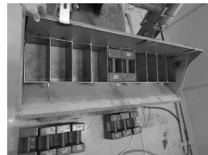
the laboratory. To simulate a variable loading weight
(0-200 kg) on a bucket, a weight holder was welded in a
bucket (Figure 2). By adding up to ten 20kg weights, up
to 200 kg of loading capacity was able to be tested.
Figure 2 Weight holder in the bucket used in the study
2.1.2 Hydraulic equipment
Figure 3a shows the connections of the EHPV and
cylinders for a boom rod. To control a FEL in a manner
that prevents sudden changes of oil flow to the cylinders
of the FEL, the EHPV (Model: SB23-EHS1, Bosch) was
used instead of a conventional manual valve. This EHPV
has three sections: the first section for boom cylinder, the
second section for bucket cylinder and the third section
for spare usage. The nominal oil flow of EHPV is from P
to A, with the B port at 100 L/min, but for this laboratory
usage, the FEL max oil flow was set as 17.5 L/min to
meet a requirement of the FEL (ML426) specification.
The oil flow target value can be set as the default by
means of a J1939 message. The J1939 message adheres to
the general CAN 2.0B conventions, as described in Table
1.
Figure 3b shows the hydraulic supply unit that sends
hydraulic oil to the EHPV valve. To support a hydraulic
oil flow to the EHPV, a 15kW DC motor with a gear
pump, which outputs 24.5L/min, was used to support the
hydraulic oil flow. Because the FEL simulator for this
applied to lower the speed of the motor until it supplies
17.5L/min.
(a)
(b)
Figure 3 EHPV valve and hydraulic oil supplier with a
pressure sensor
(a)EHPV valve (b) hydraulic oil supplier with a
pressure sensor
2.1.3 CAN signal generator for a loader control
Figure 4 shows the virtual ECUs, the CAN adapter
and the data logging equipment. To control an EHPV,
virtual ECUs were designed in a PC environment using
the ECU development tool (CANoe). The messages of
the ECUs were transmitted via a CAN adapter (VN1630,
Vector Co., Germany). To read the sensor signals coming
from a potentiometer attached onto the cylinders of the
boom and bucket of the FEL, the data logging equipment
was connected to ani-7 laptop computer. Figure 4 CAN message generator system
2.2 Topology of ECUs and components of FEL control
system
Table 1 Loader ECU messages and signals
Msg (ID) Signal Start bit Length Byte order Type Initial value Loader_ECU_sensor
_value0 (0x15x)
Loader_ECU_valve0A_pressure 0 32 Intel Float 0
Loader_ECU_valve0B_pressure 32 32 Intel Float 0
Loader_ECU_sensor _value1 (0x16x)
Loader_ECU_hydro_main_supply 0 32 Intel Float 0
Loader_ECU_sensor _value2 (0x17x)
Loader_ECU_horizontal_body 0 32 Intel Float 0
Loader_ECU_horizontal_boom 32 32 Intel Float 0
Loader_ECU_sensor _value3 (0x18x)
Loader_ECU_poten_meter_boom 0 32 Intel Float 0
2.2.1 Network topology
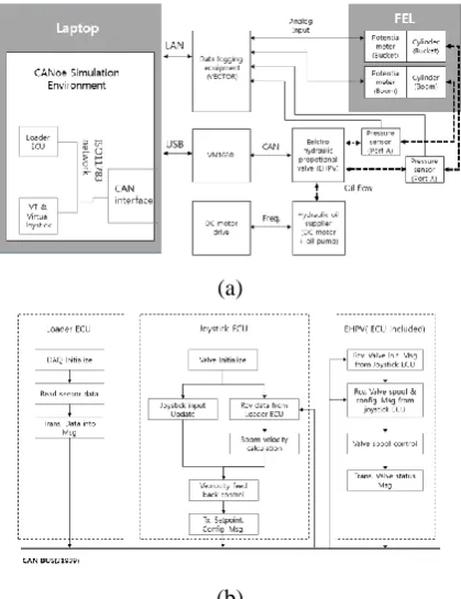
To control the FEL, two ECUs were designed in a
virtual environment: joystick ECU for a data analysis
using an algorithm that sends TX messages to the EHPV
and loader ECU that reads the sensor signals of the
position of the FEL (Figure 9a). When loader ECU
receives sensor signals, loader ECU converts into a
message and send them to a CAN bus for an EHPV to
decide set points. (ISO, 2002b). A valve ECU is
integrated into an EHPV, which receives and send
messages in accordance with the J1939 standard. For this
loader control system, three ECUs were involved in the
communication. All of the network buses used the J1939
protocol to share the network bus with an ECU of the
EHPV. Figure9b shows the processes of each ECU.
(a)
(b)
Figure 9 Simulated ECU topology for the FEL loader
controland flow chart of the ECUs
(a) Simulated ECU topology for the FEL loader control
(b) Flow chart of the ECUs
2.2.2 FEL control message
For the FEL control, the J1939 messages of the loader
ECU and the joystick ECU were assigned to a database,
as described Tables 1 and 2, respectively. Eight signals,
i.e., pressure of valve A, pressure of valve B, main supply
pressure, boom potentiometer, bucket potentiometer,
body angle and bucket angle, were generated to transmit
digitally converted signals from the sensors attached on
FEL. The message data field was limited to eight bytes.
As a result, these eight signals were transmitted in four
messages. The joystick ECU performs EHPV control,
generating the required signals and the messages defined
by the EHPV manual (Rexroth, 2012). The EHPV ECU
receives four messages: set point, configuration,
parameter assignment and flash; the EHPV ECU
transmits three messages: status, parameter assignment,
and flash. Out of seven messages, two messages of the
setpoint, which sets the spool operation, and the
configuration, which sets a ramp time, are generated in a
joystick ECU. A status message of EHPV shows the
valve status, such as the error, valve temperature, oil flow,
and maximum oil flow. The parameter assignment
message is assigned a valve number by transmitting to the
EHPV and then the EHPV transmitting back to the CAN
bus if a new assigned valve number is saved. When a
valve number is assigned, only one valve should be
connected to the CAN bus; otherwise, more than one
2.3 Shock absorbing algorithm
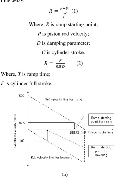
EHPV has its own ramp time function that supports a
ramp time from 0.2 - 4.3 s. To find when a ramp time
must activate, the reference line, which was determined
from a damping parameter, was defined in advance
(Figure 10). Next, when the measured boom cylinder rod
velocity reached at a reference velocity, as shown in
Figure 10, the ramp function was activated. On one hand,
as the damping parameter value rises, the ramp time
becomes shorter, thereby generating more shock to the
front-end loader. On the other hand, a longer ramp time
results in a slow response. To balance these counteracting
effects, the proper damping parameter value must be
selected. In this experiment, the damping parameter was
set to 500 after observing the movements for several
damping parameter values. A maximum 350mm stroke of
the cylinders was used for a boom rod. Equation 2 is used
to determine the ramp time, which inversely depends on
the damping parameter. Equation 1 can be used to
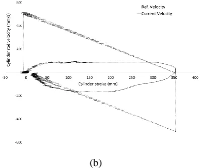
determine the ramp starting point. In the experiment, the
real cylinder rod velocity could not follow the reference
line exactly due to a delay caused by a moving average of
the cylinder rod velocity and also the typical embedded
time delay.
𝑅 =𝑃−𝐷−𝐷
𝐶
(1)
Where, R is ramp starting point;
P is piston rod velocity;
D is damping parameter;
C is cylinder stroke.
𝑅 = 0.5 𝐷𝐹 (2)
Where, T is ramp time;
F is cylinder full stroke.
(a) Table 2 Joystick ECU messages and signals
Msg (ID) Signal Start bit Length Byte
order Type Initial value
V0_config_message _from_VT (0x18FF60FEx)
V0_config_system_information 0 8 Intel Signed 0 V0_config_characteristic_form 8 8 Intel Signed 0
V0_config_gradient_raise 16 8 Intel Signed 0
V0_config_gradient_lower 24 8 Intel Signed 0
V0_config_ramp_activated_raise 32 8 Intel Signed 0 V0_config_ramp_deactivated_raise 40 8 Intel Signed 0 V0_config_ramp_activated_lower 48 8 Intel Signed 0 V0_config_ramp_deactivated_lower 56 8 Intel Signed 0
V0_setpoint_message_fr om_VT (0x18FF50FEx)
V0_set_system_information 0 8 Intel Signed 0
V0_set_diagnosis 8 8 Intel Signed 0
V0_set_operation_mode 16 8 Intel Signed 0
V0_set_oil_flow_setpoint 24 8 Intel Signed 0
V0_set_external_oil_temperature 32 8 Intel Signed 113
(b)
Figure 10 Ideal ramp starting point and experimented
ramp starting point
(a)Ideal ramp starting point (b)Experimented ramp
starting point
3 Results and discussion
Comparing the conventional performance using a
manual valve and an EHPV equipped FEL system, Figure
10 shows that the EHPV applied FEL system exhibited
superior performance at both the starting and ending
points of loader movements while delaying the time to
reach an end point compared to that of the case of not
using ramp time integration. Port A was connected to a
pressure sensor to measure the pressure applied onto a
hose that is connected to the boom cylinder; the oil in this
hose is pressurized when a piston rod moves forth to lift
the boom of the FEL to the top position. Port B is
connected to other direction of the hose. The pressure
difference of port B between controls with a ramp time
and without a ramp time did not exhibit much difference
because the weight of the FEL helped it to move to a
descending direction, resulting in no high pressure in the
hose. The pressure of port A is high when the FEL starts
from the lowest point and when it reaches the highest
point. Table 3 describes the pressures (MPa) at the points
of starting and ending with 0 kg, 100 kg, and 200 kg
loaded in a bucket along with the times to reach to the
highest position from the lowest position.
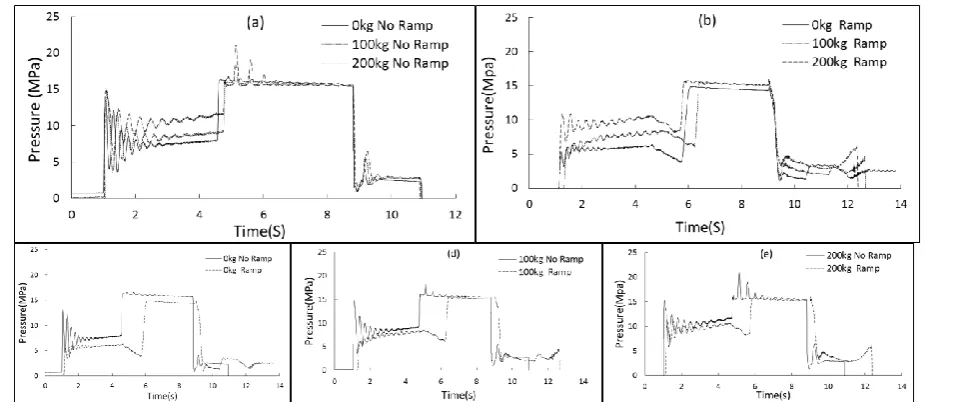
Figure 11a shows the differences of the pressure of
port A with 0 kg, 100 kg and 200 kg loaded in a bucket
without a ramp function, and Figure 11b shows the
pressures when a ramp function was used. Comparing
those two figures, a pressure reduction of port A at the
highest point was observed. From Figure11, with the
ramp applied, Figure 11b exhibits a high peak pressure,
as shown in Figure 11a, at the highest point. Table 3 Pressure on port A and the required time of the FEL movement
Load
weight,kg Pressure at the lowest position, MPa
Pressure at the highest position, MPa
Working time to reach at top position, s
No Ramp Ramp No Ramp Ramp No Ramp Ramp
0 13.57 5.23 16.42 14.82 3.58 4.91
100 14.80 6.04 17.72 15.42 3.77 5.13
4 Conclusion
This study confirmed the effectiveness of EHPV
based front-end loader control to provide shock reduction.
The EHPV based control achieved a satisfactory result
regarding the movements of a boom rod, especially at the
starting and ending points, demonstrating an improved
performance compared to an on-off hydraulic valve.
Although only a small-sized loader was tested with this
EHPV system, a large-sized loader will be expected to be
applicable simply by tuning the parameter of the damping
coefficient. Because a pre-programmed ramp function
was used, control of the ramp time was easy to handle;
however, the system was not allowed to control ramp
activation. To control a valve spool during ramping, each
discrete ramp control point must be sent repeatedly at a
constant rate by applying a closed-loop feedback
mechanism, such as PID control.
Further studies are required to reduce the time delay
of the ramp activation. In addition, tests must be
performed after a simulated front-end loader is attached
to a real tractor on a farming field.
References
Bader, M. J., L. R. Walton, and L. G. Wells. 1997. Dynamic stability of two tractor front-end loader systems. Transactions of the ASAE, 40(4): 865-869
Day, L. M. 1999. Farm work related fatalities among adults in Victoria, Australia: the human cost of agriculture. Accident Analysis & Prevention, 31(1):153-159.
Fellmeth, P. 2003. CAN-based tractor-agricultural implement communication ISO 11783. CAN Newsletter 9.
Freimann, R. 2007. A basic approach to implement guided tractor control.
Friesen, R. W., and C. Ekong. 1988. Spinal injuries due to front-end bale loaders.CMAJ: Canadian Medical Association Journal, 138(1):43.
ISO. 2002 ISO 11783: Tractors and machinery for agriculture and forestry - Serial control and communications data network, Part 7 Implement messages application layer. Geneva, Switzerland: ISO, International Organization for Standardization.
ISO. 2002 ISO 11783: Tractors and machinery for agriculture and forestry - Serial control and communications data network, Part 9 Tractor ECU. Geneva, Switzerland: ISO, International Organization for Standardization.
Rehnberg, A., and L. Drugge. 2007. Pitch Comfort Optimisation of a Front End Loader Using a Hydropneumatic Suspension: SAE Technical Paper.
Rexroth Bosch Group 2012. Technical customer documentation (TKU) - Electronics section - SB23-EHS1RD with standard software R917006776.
Worley, M. D. and V. La Saponara. 2008. A simplified dynamic model for front-end loader design. Proceedings of the Institution of Mechanical Engineers, Part C: Journal of
Mechanical Engineering Science Vol. 222: 2231 Figure 11 Hydraulic oil pressure on port A with 0 kg, 100 kg, and 200 kg loaded on a bucket for both manual