443
Electric Charge and
Electric Field
CONTENTS
16–1 Static Electricity; Electric Charge and Its Conservation 16–2 Electric Charge in the Atom 16–3 Insulators and Conductors 16–4 Induced Charge;
the Electroscope 16–5 Coulomb’s Law
16–6 Solving Problems Involving Coulomb’s Law and Vectors 16–7 The Electric Field
16–8 Electric Field Lines 16–9 Electric Fields and
Conductors
*16–10 Electric Forces in Molecular Biology: DNA Structure and Replication
*16–11 Photocopy Machines and Computer Printers Use Electrostatics
*16–12 Gauss’s Law
C
H
A
P
T
E
R
†As we discussed in Section 5–9, physicists in the twentieth century came to recognize four different fundamental forces in nature: (1) gravitational force, (2) electromagnetic force (we will see later that electric and magnetic forces are intimately related), (3) strong nuclear force, and (4) weak nuclear force. The last two forces operate at the level of the nucleus of an atom. Recent theory has combined the electromagnetic and weak nuclear forces so they are now considered to have a common origin known as the electroweak force. We discuss the other forces in later Chapters.
CHAPTER-OPENING QUESTION—Guess now!
Two identical tiny spheres have the same electric charge. If their separation is doubled, the force each exerts on the other will be
(a) half. (b) double.
(c) four times larger. (d) one-quarter as large. (e) unchanged.
T
he word “electricity” may evoke an image of complex modern technology: lights, motors, electronics, and computers. But the electric force plays an even deeper role in our lives. According to atomic theory, electric forces between atoms and molecules hold them together to form liquids and solids, and electric forces are also involved in the metabolic processes that occur within our bodies. Many of the forces we have dealt with so far, such as elastic forces, the normal force, and friction and other contact forces (pushes and pulls), are now considered to result from electric forces acting at the atomic level. Gravity, on the other hand, is a separate force.†16
This comb has acquired a static electric charge, either from passing through hair, or being rubbed by a cloth or paper towel. The electrical charge on the comb induces a polarization (separation of charge) in scraps of paper, and thus attracts them.444
CHAPTER 16The earliest studies on electricity date back to the ancients, but only since the late 1700s has electricity been studied in detail. We will discuss the development of ideas about electricity, including practical devices, as well as its relation to magnetism, in the next seven Chapters.
16–1
Static Electricity; Electric Charge
and Its Conservation
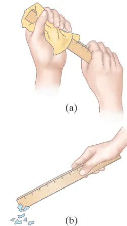
The word electricitycomes from the Greek word elektron, which means “amber.” Amber is petrified tree resin, and the ancients knew that if you rub a piece of amber with a cloth, the amber attracts small pieces of leaves or dust. A piece of hard rubber, a glass rod, or a plastic ruler rubbed with a cloth will also display this “amber effect,” or static electricityas we call it today. You can readily pick up small pieces of paper with a plastic comb or ruler that you have just vigorously rubbed with even a paper towel. See the photo on the previous page and Fig. 16–1. You have probably experienced static electricity when combing your hair or when taking a synthetic blouse or shirt from a clothes dryer. And you may have felt a shock when you touched a metal doorknob after sliding across a car seat or walking across a synthetic carpet. In each case, an object becomes “charged” as a result of rubbing, and is said to possess a net electric charge.
Is all electric charge the same, or is there more than one type? In fact, there aretwotypes of electric charge, as the following simple experiments show. A plastic ruler suspended by a thread is vigorously rubbed with a cloth to charge it. When a second plastic ruler, which has been charged in the same way, is brought close to the first, it is found that one ruler repelsthe other. This is shown in Fig. 16–2a. Similarly, if a rubbed glass rod is brought close to a second charged glass rod, again a repulsive force is seen to act, Fig. 16–2b. However, if the charged glass rod is brought close to the charged plastic ruler, it is found that they attracteach other, Fig. 16–2c. The charge on the glass must therefore be different from that on the plastic. Indeed, it is found experimentally that all charged objects fall into one of two categories. Either they are attracted to the plastic and repelled by the glass; or they are repelled by the plastic and attracted to the glass. Thus there seem to be two, and only two, types of electric charge. Each type of charge repels the same type but attracts the opposite type. That is:unlike charges attract; like charges repel. The two types of electric charge were referred to as positiveandnegativeby the American statesman, philosopher, and scientist Benjamin Franklin (1706–1790). The choice of which name went with which type of charge was arbitrary. Franklin’s choice set the charge on the rubbed glass rod to be positive charge, so the charge on a rubbed plastic ruler (or amber) is called negative charge. We still follow this convention today.
Franklin argued that whenever a certain amount of charge is produced on one object, an equal amount of the opposite type of charge is produced on another object. The positive and negative are to be treated algebraically, so during any process, the net change in the amount of charge produced is zero. For example, when a plastic ruler is rubbed with a paper towel, the plastic acquires a negative charge and the towel acquires an equal amount of positive charge. The charges are separated, but the sum of the two is zero.
This is an example of a law that is now well established: the law of conservation of electric charge, which states that
the net amount of electric charge produced in any process is zero;
or, said another way,
no net electric charge can be created or destroyed.
If one object (or a region of space) acquires a positive charge, then an equal amount of negative charge will be found in neighboring areas or objects. No violations have ever been found, and the law of conservation of electric charge is as firmly established as those for energy and momentum.
(a)
(b)
FIGURE 16–1 (a) Rub a plastic ruler with a cloth or paper towel, and (b) bring it close to some tiny pieces of paper.
ⴙⴙ ⴙⴙ ⴙⴙ
ⴚ ⴚ ⴚⴚ ⴚⴚ
ⴚⴚⴚⴚ
ⴚⴚ
ⴚⴚⴚⴚ
ⴚⴚ
ⴙⴙⴙⴙ
ⴙⴙ
ⴙⴙ ⴙⴙ ⴙⴙ
(a) Two charged plastic rulers repel
(b) Two charged glass rods repel
(c) Charged glass rod attracts charged plastic ruler
FIGURE 16–2 Like charges repel one another; unlike charges attract. (Note color coding: we color positive charged objects pink or red, and negative charges blue-green. We use these colors especially for point charges, but not always for real objects.)
SECTION 16–3 Insulators and Conductors
445
16–2
Electric Charge in the Atom
Only within the past century has it become clear that an understanding of electric-ity originates inside the atom itself. In later Chapters we will discuss atomic structure and the ideas that led to our present view of the atom in more detail. But it will help our understanding of electricity if we discuss it briefly now.
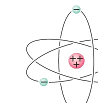
A simplified model of an atom shows it as having a tiny but massive, positively charged nucleus surrounded by one or more negatively charged electrons (Fig. 16–3). The nucleus contains protons, which are positively charged, and neutrons, which have no net electric charge. All protons and all electrons have exactly the same magnitude of electric charge; but their signs are opposite. Hence neutral atoms, having no net charge, contain equal numbers of protons and electrons. Sometimes an atom may lose one or more of its electrons, or may gain extra electrons, in which case it will have a net positive or negative charge and is called an ion.
In solid materials the nuclei tend to remain close to fixed positions, whereas some of the electrons may move quite freely. When an object is neutral, it contains equal amounts of positive and negative charge. The charging of a solid object by rubbing can be explained by the transfer of electrons from one object to the other. When a plastic ruler becomes negatively charged by rubbing with a paper towel, electrons are transferred from the towel to the plastic, leaving the towel with a positive charge equal in magnitude to the negative charge acquired by the plastic. In liquids and gases, nuclei or ions can move as well as electrons.
Normally when objects are charged by rubbing, they hold their charge only for a limited time and eventually return to the neutral state. Where does the charge go? Usually the excess charge “leaks off” onto water molecules in the air. This is because water molecules are polar—that is, even though they are neutral, their charge is not distributed uniformly, Fig. 16–4. Thus the extra electrons on, say, a charged plastic ruler can “leak off” into the air because they are attracted to the positive end of water molecules. A positively charged object, on the other hand, can be neutralized by transfer of loosely held electrons from water mole-cules in the air. On dry days, static electricity is much more noticeable since the air contains fewer water molecules to allow leakage of charge. On humid or rainy days, it is difficult to make any object hold a net charge for long.
16–3
Insulators and Conductors
Suppose we have two metal spheres, one highly charged and the other electrically neutral (Fig. 16–5a). If we now place a metal object, such as a nail, so that it touches both spheres (Fig. 16–5b), the previously uncharged sphere quickly becomes charged. If, instead, we had connected the two spheres by a wooden rod or a piece of rubber (Fig. 16–5c), the uncharged ball would not become noticeably charged. Materials like the iron nail are said to be conductorsof electricity, whereas wood and rubber are nonconductorsorinsulators.
Metals are generally good conductors, whereas most other materials are insulators (although even insulators conduct electricity very slightly). Nearly all natural materials fall into one or the other of these two distinct categories. However, a few materials (notably silicon and germanium) fall into an intermediate category known as semiconductors.
From the atomic point of view, the electrons in an insulating material are bound very tightly to the nuclei. In a good metal conductor, on the other hand, some of the electrons are bound very loosely and can move about freely within the metal (although they cannot leavethe metal easily) and are often referred to as
free electronsorconduction electrons. When a positively charged object is brought close to or touches a conductor, the free electrons in the conductor are attracted by this positively charged object and move quickly toward it. If a negatively charged object is brought close to the conductor, the free electrons in the con-ductor move swiftly away from it. In a semiconcon-ductor, there are many fewer free electrons, and in an insulator, almost none.
H H
O
ⴙ ⴚ
ⴙ ⴚ
FIGURE 16–4 Diagram of a water molecule. Because it has opposite charges on different ends, it is called a “polar” molecule.
+ + + + ++
+ + + + ++
+ + +
+ + + (a)
(b)
(c)
Charged Neutral
Metal
Wood
FIGURE 16–5 (a) A charged metal sphere and a neutral metal sphere. (b) The two spheres connected by a conductor (a metal nail), which conducts charge from one sphere to the other. (c) The original two spheres connected by an insulator (wood); almost no charge is conducted.
ⴙ ⴙⴙ
ⴚ
ⴚ
ⴚ
446
CHAPTER 16 Electric Charge and Electric Field (a)Neutral metal rod(b) Metal rod acquires charge by contact Charged
metal object A
B
B
ⴙ ⴙⴙ ⴙ ⴙ
ⴙ ⴙ
ⴙ ⴙ ⴙ
ⴙ
e− passage
Neutral metal rod
+ + + –
– – (a)
Metal rod still neutral, but with a separation of charge
+ ++ +
(b)
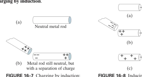
FIGURE 16–7 Charging by induction: if the rod in (b) is cut into two parts, each part will have a net charge. FIGURE 16–6 A neutral metal rod
in (a) will acquire a positive charge if placed in contact (b) with a positively charged metal object. (Electrons move as shown by the green arrow.) This is called charging by conduction.
16–4
Induced Charge; the Electroscope
Suppose a positively charged metal object A is brought close to an uncharged metal object B. If the two touch, the free electrons in the neutral one are attracted to the positively charged object and some of those electrons will pass over to it, Fig. 16–6. Since object B, originally neutral, is now missing some of its negative electrons, it will have a net positive charge. This process is called charging by conduction, or “by contact,” and the two objects end up with the same sign of charge.Now suppose a positively charged object is brought close to a neutral metal rod, but does not touch it. Although the free electrons of the metal rod do not leave the rod, they still move within the metal toward the external positive charge, leaving a positive charge at the opposite end of the rod (Fig. 16–7b). A charge is said to have been inducedat the two ends of the metal rod. No net charge has been created in the rod: charges have merely been separated. The net charge on the metal rod is still zero. However, if the metal is separated into two pieces, we would have two charged objects: one charged positively and one charged negatively. This is
charging by induction.
ⴚ ⴚ ⴚ ⴚⴚ
ⴙ ⴙ ⴙ
ⴙ
ⴙ ⴙⴙ
ⴚ (a)
(b)
(c)
+ –
+ –
+ –
+ – + –
Nonconductor
+ ++ ++ +
Insulator
Metal
Gold
leaves Glass
FIGURE 16–10 Electroscope. FIGURE 16–9 A charged object brought near a nonconductor causes a charge separation within the nonconductor’s molecules.
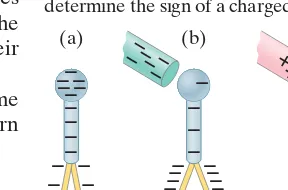
FIGURE 16–8 Inducing a charge on an object connected to ground.
Another way to induce a net charge on a metal object is to first connect it with a conducting wire to the ground (or a conducting pipe leading into the ground) as shown in Fig. 16–8a (the symbol means connected to “ground”). The object is then said to be groundedor “earthed.” The Earth, because it is so large and can conduct, easily accepts or gives up electrons; hence it acts like a reservoir for charge. If a charged object—say negative this time—is brought up close to the metal object, free electrons in the metal are repelled and many of them move down the wire into the Earth, Fig. 16–8b. This leaves the metal posi-tively charged. If the wire is now cut, the metal object will have a positive induced charge on it (Fig. 16–8c). If the wire is cut after the negative object is moved away, the electrons would all have moved from the ground back into the metal object and it would be neutral again.
Charge separation can also be done in nonconductors. If you bring a positively charged object close to a neutral nonconductor as shown in Fig. 16–9, almost no electrons can move about freely within the nonconductor. But they can move slightly within their own atoms and molecules. Each oval in Fig. 16–9 represents a molecule (not to scale); the negatively charged electrons, attracted to the external positive charge, tend to move in its direction within their molecules. Because the negative charges in the nonconductor are nearer to the external positive charge, the nonconductor as a whole is attracted to the external positive charge (see the Chapter-Opening Photo, page 443).
ⴙ ⴙ
Rod Fiber
SECTION 16–5 Coulomb’s Law
447
If a positively charged object is brought close to the knob, a separation of chargeis induced: electrons are attracted up into the knob, and the leaves become posi-tively charged, Fig. 16–11a. The two leaves repel each other as shown, because they are both positively charged. If, instead, the knob is charged by conduction (touching), the whole apparatus acquires a net charge as shown in Fig. 16–11b. In either case, the greater the amount of charge, the greater the separation of the leaves.
Note that you cannot tell the sign of the charge in this way, since negative charge will cause the leaves to separate just as much as an equal amount of positive charge; in either case, the two leaves repel each other. An electroscope can, however, be used to determine the sign of the charge if it is first charged by conduction: say, negatively, as in Fig. 16–12a. Now if a negative object is brought close, as in Fig. 16–12b, more electrons are induced to move down into the leaves and they separate further. If a positive charge is brought close instead, the electrons are induced to flow upward, so the leaves are less negative and their separation is reduced, Fig. 16–12c.
The electroscope was used in the early studies of electricity. The same principle, aided by some electronics, is used in much more sensitive modern
electrometers.
†Coulomb reasoned that if a charged conducting sphere is placed in contact with an identical uncharged sphere, the charge on the first would be shared equally by the two of them because of symmetry. He thus had a way to produce charges equal to and so on, of the original charge.
‡The validity of Coulomb’s law today rests on precision measurements that are much more sophisticated than Coulomb’s original experiment. The exponent 2 on rin Coulomb’s law has been shown to be accurate to 1 part in 1016[that is,26A1 *10–16B].
1 4, 1 2,
16–5
Coulomb’s Law
We have seen that an electric charge exerts a force of attraction or repulsion on other electric charges. What factors affect the magnitude of this force? To find an answer, the French physicist Charles Coulomb (1736–1806) investigated electric forces in the 1780s using a torsion balance (Fig. 16–13) much like that used by Cavendish for his studies of the gravitational force (Chapter 5).
Precise instruments for the measurement of electric charge were not available in Coulomb’s time. Nonetheless, Coulomb was able to prepare small spheres with different magnitudes of charge in which the ratio of the charges was known.† Although he had some difficulty with induced charges, Coulomb was able to argue that the electric force one tiny charged object exerts on a second tiny charged object is directly proportional to the charge on each of them. That is, if the charge on either one of the objects is doubled, the force is doubled; and if the charge on both of the objects is doubled, the force increases to four times the original value. This was the case when the distance between the two charges remained the same. If the distance between them was allowed to increase, he found that the force decreased with the square of the distancebetween them. That is, if the distance was doubled, the force fell to one-fourth of its original value. Thus, Coulomb concluded, the magnitude of the force Fthat one small charged object exerts on a second one is proportional to the product of the magnitude of the charge on one, times the magnitude of the charge on the other, and inversely proportional to the square of the distance rbetween them (Fig. 16–14). As an equation, we can write Coulomb’s lawas
[magnitudes] (16;1)
wherekis a proportionality constant.‡ F = kQ1Q2
r2 ,
Q2,
Q1,
COULOMB’S LAW
(a) (b)
ⴙ ⴙ ⴙ
ⴙ ⴙ ⴙ ⴙ
ⴙ ⴙ ⴙ
ⴙ ⴙ ⴙ ⴙ
ⴚⴚⴚ
ⴙ ⴙ
ⴙ
ⴙ ⴙ ⴙ
ⴚ ⴚ ⴚ
ⴚ ⴚ ⴚ
ⴚ ⴚ
ⴚ
ⴚ ⴚⴚⴚⴚ
ⴚ ⴚ ⴚ ⴚ ⴚ ⴚ ⴚ ⴚⴚ
ⴚⴚ ⴚ
ⴚ ⴚⴚⴚⴚⴚⴚⴚⴚ
ⴚ ⴚ ⴚ ⴚ ⴚ ⴚ
ⴚ
ⴚ ⴚ ⴚ
ⴚⴚⴚⴚ ⴚ ⴚ ⴚ ⴚ ⴚ
(c)
(a) (b)
Q2 Q1
r
FIGURE 16–14 Coulomb’s law, Eq. 16–1, gives the force between two point charges, and a distance r
apart.
Q2,
Q1
As we just saw, Coulomb’s law, Eq. 16–1,
[magnitudes] (16;1)
gives the magnitudeof the electric force that either charge exerts on the other. The directionof the electric force is always along the line joining the two charges. If the two charges have the same sign, the force on either charge is directed away from the other (they repel each other). If the two charges have opposite signs, the force on one is directed toward the other (they attract). See Fig. 16–15. Notice that the force one charge exerts on the second is equal but opposite to that exerted by the second on the first, in accord with Newton’s third law.
The SI unit of charge is the coulomb(C). The precise definition of the coulomb today is in terms of electric current and magnetic field, and will be discussed later (Section 20–6). In SI units, the constant kin Coulomb’s law has the value
or, when we only need two significant figures,
Thus, 1 C is that amount of charge which, if placed on each of two point objects that are 1.0 m apart, will result in each object exerting a force of
on the other. This would be an enormous force, equal to the weight of almost a million tons. We rarely encounter charges as large as a coulomb.†
Charges produced by rubbing ordinary objects (such as a comb or plastic ruler) are typically around a microcoulomb or less. Objects that carry a positive charge have a deficit of electrons, whereas negatively charged objects have an excess of electrons. The charge on one electron has been deter-mined to have a magnitude of about and is negative. This is the smallest charge observed in nature,‡and because it is fundamental, it is given the symboleand is often referred to as the elementary charge:
Note that eis defined as a positive number, so the charge on the electron is (The charge on a proton, on the other hand, is ) Since an object cannot gain or lose a fraction of an electron, the net charge on any object must be an integral multiple of this charge. Electric charge is thus said to be quantized(existing only in discrete amounts: 1e, 2e, 3e, etc.). Because eis so small, however, we normally do not notice this discreteness in macroscopic charges ( requires about electrons), which thus seem continuous.
Coulomb’s law looks a lot like the lawof universal gravitation,
which expresses the magnitude of the gravitational force a mass exerts on a mass (Eq. 5–4). Both are inverse square laws Both also have a proportionality to a property of each object—mass for gravity, electric charge for electricity. And both act over a distance (that is, there is no need for contact). A major difference between the two laws is that gravity is always an attractive force, whereas the electric force can be either attractive or repulsive. Electric charge comes in two types, positive and negative; gravitational mass is only positive.
The constant kin Eq. 16–1 is often written in terms of another constant, called the permittivity of free space. It is related to kby Coulomb’s law can be written
(16;2)
where
0 =
1
4pk = 8.85 * 10
–12C2兾Nm2.
F = 1
4p0
Q1Q2
r2 ,
k = 1兾4p0.
0,
AF r 1兾r2B.
m2
m1
F = Gm1m2兾r2,
1013
1mC ±e.
–e. e = 1.6022 * 10–19C L 1.6 * 10–19C.
1.6022 * 10–19C,
A1mC = 10–6CB
A9.0 * 109Nm2兾C2B(1.0C)(1.0C)兾(1.0m)2 = 9.0 * 109N
k L 9.0 * 109Nm2兾C2.
k = 8.988 * 109Nm2兾C2 F = kQ1Q2
r2 ,
448
CHAPTER 16 F12= force on 1 due to 212 21
2 1
12
F21= force on 2 due to 1
(a)
(b)
(c)
21
1 2
2 1
12 21
ⴙ
ⴙ
ⴙ
ⴚ ⴚ ⴚ
FB
FB
FB
FB
FB FB
FIGURE 16–15 The direction of the static electric force one point charge exerts on another is always along the line joining the two charges, and depends on whether the charges have the same sign as in (a) and (b), or opposite signs (c).
†In the once common cgs system of units,kis set equal to 1, and the unit of electric charge is called the electrostatic unit(esu) or the statcoulomb. One esu is defined as that charge, on each of two point objects 1 cm apart, that gives rise to a force of 1 dyne.
‡According to the Standard Model of elementary particle physics, subnuclear particles called quarks have a smaller charge than the electron, equal to or Quarks have not been detected directly as isolated objects, and theory indicates that free quarks may not be detectable.
2 3e. 1 3e
SECTION 16–5 Coulomb’s Law
449
EXERCISE B In Example 16–2, how is the direction of F12related to the direction of F21?
Equation 16–2 looks more complicated than Eq. 16–1, but other fundamental equations we haven’t seen yet are simpler in terms of rather than k. It doesn’t matter which form we use since Eqs. 16–1 and 16–2 are equivalent. (The latest precise values of eand are given inside the front cover.)†
Equations 16–1 and 16–2 apply to objects whose size is much smaller than the distance between them. Ideally, it is precise for point charges(spatial size negligible compared to other distances). For finite-sized objects, it is not always clear what value to use for r, particularly since the charge may not be distributed uniformly on the objects. If the two objects are spheres and the charge is known to be distributed uniformly on each, then ris the distance between their centers.
Coulomb’s law describes the force between two charges when they are at rest. Additional forces come into play when charges are in motion, and will be dis-cussed in later Chapters. In this Chapter we discuss only charges at rest, the study of which is called electrostatics, and Coulomb’s law gives the electrostatic force. When calculating with Coulomb’s law, we usually use magnitudes, ignoring signs of the charges, and determine the direction of a force separately based on whether the force is attractive or repulsive.
0
0
EXERCISE A Return to the Chapter-Opening Question, page 443, and answer it again
now. Try to explain why you may have answered differently the first time.
Electric force on electron by proton. Determine the magnitude and direction of the electric force on the electron of a hydrogen atom exerted by the single proton that is the atom’s nucleus. Assume the average distance between the revolving electron and the proton is
Fig. 16–16.
APPROACH To find the force magnitude we use Coulomb’s law, (Eq. 16–1), with The electron and proton have the same magnitude of charge, e, so
SOLUTION The magnitude of the force is
The direction of the force on the electron is toward the proton, because the charges have opposite signs so the force is attractive.
= 8.2 * 10–8N. F = kQ1Q2
r2 =
A9.0 * 109Nm2兾C2BA1.6 * 10–19CBA1.6 * 10–19CB
A0.53 * 10–10mB2
Q1 = Q2 = 1.6 * 10–19C.
r = 0.53 * 10–10m. F = k Q1Q2兾r2
r = 0.53 * 10–10m,
AQ2 = ±eB
EXAMPLE 16;1
Which charge exerts the greater force?
Two positive point charges, and are separated by a
distance Fig. 16–17. Which is larger in magnitude, the force that exerts on or the force that exerts on
RESPONSE From Coulomb’s law, the force on exerted by is
The force on exerted by is
which is the same magnitude. The equation is symmetric with respect to the two charges, so
NOTENewton’s third law also tells us these two forces must have equal magnitude. F21 = F12.
F21 = k
Q2Q1
l2
Q1
Q2
F12 = k
Q1Q2
l2 .
Q2
Q1
Q1?
Q2
Q2,
Q1
l,
Q2 = 1mC,
Q1 = 50mC
CONCEPTUAL EXAMPLE 16;2
P R O B L E M S O L V I N G Use magnitudes in Coulomb’s law; find force direction from signs of charges
l Q2= 1 mC
Q1= 50mC
FIGURE 16–17 Example 16–2.
ⴙ Q2 ⴚ Q1
r
Proton Electron
F
B
FIGURE 16–16 Example 16–1.
†Our convention for units, such as for means is in the denominator. That is, means and C2兾(Nm2) does notmeanAC2兾NBm2= C2m2兾N.
C2兾Nm2
m2 0,
450
CHAPTER 16 Electric Charge and Electric Field 12
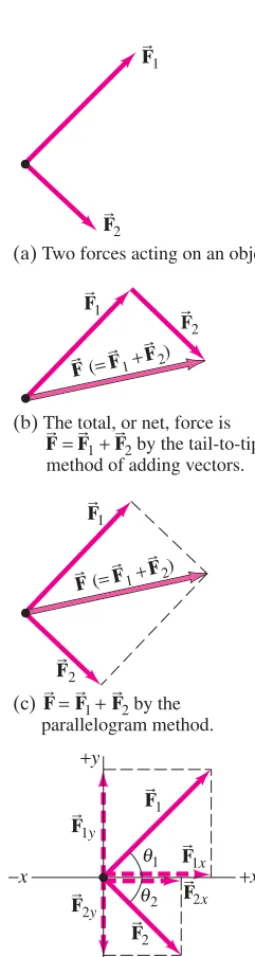
(a)Two forces acting on an object.
1
F2
= 1+ 2
(b)The total, or net, force is by the tail-to-tip method of adding vectors.
1
2
(c) = 1+ 2by the parallelogram method.
2) 1+
(=
2 1x
+x −x
+y
−y
2y θ2 2x
θ1
(d) 1and 2resolved into their
x and y components.
1y FB
F
B
FB B
FB FB FB
F
B
F
B BF F B 2) 1+
(= F
B BF F B
F
B
FB FB FB
FB
F
B
FB F
B 1 FB
F
B
FB FB
FIGURE 16–18 Review of vector addition.
Keep in mind that Coulomb’s law, Eq. 16–1 or 16–2, gives the force on a charge due to only oneother charge. If several (or many) charges are present, the net force on any one of themwill be thevector sum of the forces due to each of the others. This principle of superpositionis based on experiment, and tells us that electric force vectors add like any other vector. For example, if you have a system of four charges, the net force on charge 1, say, is the sum of the forces exerted on charge 1 by charges 2, 3, and 4. The magnitudes of these three forces are determined from Coulomb’s law, and then are added vectorially.
16–6
Solving Problems Involving
Coulomb’s Law and Vectors
The electric force between charged particles at rest (sometimes referred to as theelectrostatic forceor as the Coulomb force) is, like all forces, a vector: it has both magnitude and direction. When several forces act on an object (call them etc.), the net force on the object is the vector sum of all the forces acting on it:
This is the principle of superposition for forces. We studied how to add vectors in Chapter 3; then in Chapter 4 we used the rules for adding vectors to obtain the net force on an object by adding the different vector forces acting on it. It might be useful now to review Sections 3–2, 3–3, and 3–4. Here is a brief review of vectors.
Vector Addition Review
Suppose two vector forces, and act on an object (Fig. 16–18a). They can be added using the tail-to-tip method (Fig. 16–18b) or by the parallelogram method (Fig. 16–18c), as discussed in Section 3–2. These two methods are useful for understanding a given problem (for getting a picture in your mind of what is going on). But for calculatingthe direction and magnitude of the resultant sum, it is more precise to use the method of adding components. Figure 16–18d shows the forces and resolved into components along chosen x andyaxes (for more details, see Section 3–4). From the definitions of the trigonometric functions (Figs. 3–11 and 3–12), we have
We add up the xandycomponents separately to obtain the components of the resultant force which are
The magnitude of the resultant (or net) force is
The direction of is specified by the angle that makes with the xaxis, which is given by
Adding Electric Forces; Principle of Superposition
When dealing with several charges, it is helpful to use double subscripts on each of the forces involved. The first subscript refers to the particle onwhich the force acts; the second refers to the particle that exerts the force. For example, if we have three charges,FB31means the force exerted onparticle 3 byparticle 1.
tanu = Fy Fx
.
F
B u
FB
F = 3Fx2 + Fy2.
FB
Fy = F1y + F2y = F1sinu1 - F2sinu2.
Fx = F1x + F2x = F1cosu1 + F2cosu2,
FB,
F1y = F1sinu1
F2y = –F2sinu2.
F1x = F1cosu1
F2x = F2cosu2
FB2
FB1
FB2,
FB1
FBnet = FB1 + F
B
2 + p.
FBnet
FB1,F
B
SECTION 16–6 Solving Problems Involving Coulomb’s Law and Vectors
451
As in all problem solving, it is very important to draw a diagram, in particulara free-body diagram (Chapter 4) for each object, showing all the forces acting on that object. In applying Coulomb’s law, we can deal with charge magnitudes only (leaving out minus signs) to get the magnitude of each force. Then determine separately the direction of the force physically (along the line joining the two particles: like charges repel, unlike charges attract), and show the force on the diagram. (You could determine direction first if you like.) Finally, add all the forces on one object together as vectors to obtain the net force on that object.
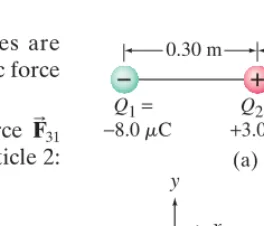
Three charges in a line. Three charged particles are arranged in a line, as shown in Fig. 16–19a. Calculate the net electrostatic force on particle 3 (the on the right) due to the other two charges.
APPROACH The net force on particle 3 is the vector sum of the force exerted on particle 3 by particle 1 and the force exerted on 3 by particle 2:
SOLUTION The magnitudes of these two forces are obtained using Coulomb’s law, Eq. 16–1:
where is the distance from to Similarly,
Since we were calculating the magnitudes of the forces, we omitted the signs of the charges. But we must be aware of them to get the direction of each force. Let the line joining the particles be the xaxis, and we take it positive to the right. Then, because is repulsive and is attractive, the directions of the forces are as shown in Fig. 16–19b: points in the positive xdirection (away from ) and points in the negative x direction (toward ). The net force on particle 3 is then
The magnitude of the net force is 1.5 N, and it points to the left.
NOTE Charge acts on charge just as if were not there (this is the principle of superposition). That is, the charge in the middle, in no way blocks the effect of charge acting on Naturally, exerts its own force onQ3.
Q2
Q3.
Q1
Q2,
Q2
Q3
Q1
= –2.7N + 1.2N = –1.5N. F = –F32 + F31
Q2
F32
Q1
F31
FB32
F
B
31
= A9.0 * 10
9Nm2兾C2BA4.0 * 10–6CBA3.0 * 10–6CB
(0.20m)2 = 2.7 N.
F32 = k
Q3Q2
r322
Q1.
Q3
r31 = 0.50m
= A9.0 * 10
9Nm2兾C2BA4.0 * 10–6CBA8.0 * 10–6CB
(0.50m)2 = 1.2 N,
F31 = k
Q3Q1
r312
FB = FB31 + F
B
32.
FB32
F
B
31
–4.0mC
EXAMPLE 16;3
C A U T I O N
Each charge exerts its own force. No charge blocks the effect of the others
ⴙ ⴚ
ⴚ ⴚ
0.30 m 0.20 m
32
Q1= −8.0 C
Q2= +3.0 C
Q3= −4.0 C
(a)
Q3
31
(b) x
y
x
m m m
B B
FB FB
FIGURE 16–19 Example 16–3.
EXERCISE C Determine the magnitude and direction of the net force on charge in
Fig. 16–19a.
452
CHAPTER 16 Electric Charge and Electric FieldElectric force using vector components. Calculate the net electrostatic force on charge shown in Fig. 16–20a due to the charges
and
APPROACH We use Coulomb’s law to find the magnitudes of the individual forces. The direction of each force will be along the line connecting to or The forces and have the directions shown in Fig. 16–20a, since
exerts an attractive force on and exerts a repulsive force. The forces and are notalong the same line, so to find the resultant force on we resolve
and into xandycomponents and perform the vector addition.
SOLUTION The magnitudes of and are (ignoring signs of the charges since we know the directions)
(We keep 3 significant figures until the end, and then keep 2 because only 2 are given.) We resolve into its components along the xandyaxes, as shown in Fig. 16–20a:
The force has only a ycomponent. So the net force on has components
The magnitude of the net force is
and it acts at an angle (see Fig. 16–20b) given by
so
NOTE Because and are not along the same line, the magnitude of is not equal to the sum (or difference as in Example 16–3) of the separate magni-tudes. That is, is not equal to nor does it equal Instead we had to do vector addition.
F32 - F31.
F31 + F32;
F3
FB3
F
B
32
FB31
u = tan–1(2.13) = 65°.
tanu = Fy Fx =
255N
120N = 2.13,
u
F = 3Fx2 + Fy2 = 3(120N)2 + (255N)2 = 280N;
Fy = F32 + F31y = 325N - 70N = 255N.
Fx = F31x = 120N,
Q3
FB F
B
32
F31y = –F31sin 30° = –(140N)sin 30° = –70N.
F31x = F31cos 30° = (140N)cos 30° = 120N,
FB31
F32 = k
Q3Q2
r322
= A9.0 * 10
9Nm2兾C2BA6.5 * 10–5CBA5.0 * 10–5CB
(0.30m)2 = 325 N.
F31 = k
Q3Q1
r312
= A9.0 * 10
9Nm2兾C2BA6.5 * 10–5CBA8.6 * 10–5CB
(0.60m)2 = 140 N,
FB32
FB31
FB32
FB31
Q3
FB32
F
B
31
Q2
Q3,
Q1
FB32
F
B
31
Q2.
Q1
Q3
Q2.
Q1
Q3
EXAMPLE 16;4
F31x y
x
32
31 F31y Q3= +65 C
Q2= +50 C
52 cm
60 cm
90°
30° 30°
30 cm
Q1= −86 C
m
m
m
(a) (b)
y
x
32
31 Q3 u
FB
FB F
B
FB
F B FIGURE 16–20 Determining the
forces for Example 16–4. (a) The directions of the individual forces are as shown because is repulsive (the force on is in the direction away from because and are both positive) whereas is attractive ( and have opposite signs), so points toward
(b) Adding to to obtain the net force FB.
FB31
FB32
Q1.
F B
31
Q1
Q3
F B
31
Q2
Q3
Q2
Q3
F B
SECTION 16–7 The Electric Field
453
y
x = 31+ 32
34
u= 65°
Q4 Q3
115°
FB FB FB
F
B r ?
FIGURE 16–21 Example 16–5 and Exercise D: exerts force that makes the net force on Q3zero.
AFB34B
Q4
Make the force on zero. In Fig. 16–20, where could you place a fourth charge, so that the net force on
would be zero?
RESPONSE By the principle of superposition, we need a force in exactly the opposite direction to the resultant due to and that we calculated in Example 16–4, Fig. 16–20b. Our force must have magnitude 290 N, and must point down and to the left of in Fig. 16–20b, in the direction opposite to So Q4must be along this line. See Fig. 16–21.
FB. Q3
Q1
Q2
F
B Q3
Q4 = –50mC,
Q3 CONCEPTUAL EXAMPLE 16;5
EXERCISE D In Example 16–5, what distance rmust be Q4 from Q3?
EXERCISE E (a) Consider two point charges, which are fixed a distance d
apart. Can you find a location where a third positive charge Qcould be placed so that the net electric force on this third charge is zero? (b) What if the first two charges were both±Q?
±Q and –Q,
16–7
The Electric Field
Many common forces might be referred to as “contact forces,” such as your hands pushing or pulling a cart, or a tennis racket hitting a tennis ball.
In contrast, both the gravitational force and the electrical force act over a dis-tance: there is a force between two objects even when the objects are not touching. The idea of a force acting at a distance was a difficult one for early thinkers. Newton himself felt uneasy with this idea when he published his law of universal gravitation. A helpful way to look at the situation uses the idea of the field, devel-oped by the British scientist Michael Faraday (1791–1867). In the electrical case, according to Faraday, an electric field extends outward from every charge and permeates all of space (Fig. 16–22). If a second charge (call it ) is placed near the first charge, it feels a force exerted by the electric field that is there (say, at point P in Fig. 16–22). The electric field at point P is considered to interact directly with charge to produce the force on
We can in principle investigate the electric field surrounding a charge or group of charges by measuring the force on a small positive test chargewhich is at rest. By a test charge we mean a charge so small that the force it exerts does not significantly affect the charges that create the field. If a tiny positive test chargeqis placed at various locations in the vicinity of a single positive charge Q as shown in Fig. 16–23 (points A, B, C), the force exerted on qis as shown. The force at B is less than at A because B’s distance from Q is greater (Coulomb’s law); and the force at C is smaller still. In each case, the force on q is directed radially away from Q. The electric field is defined in terms of the force on such a positive test charge. In particular, the electric field, at any point in space is defined as the force exerted on a tiny positive test charge placed at that point divided by the magnitude of the test charge q:
(16;3)
More precisely, is defined as the limit of as qis taken smaller and smaller, approaching zero. That is, qis so tiny that it exerts essentially no force on the other charges which created the field. From this definition (Eq. 16–3), we see that the electric field at any point in space is a vector whose direction is the direction of the force on a tiny positive test charge at that point, and whose magnitude is theforce per unit charge. Thus has SI units of newtons per coulomb
The reason for defining as (with ) is so that does not depend on the magnitude of the test charge q. This means that describes only the effect of the charges creating the electric field at that point.
EB EB
q S 0
FB兾q EB
(N兾C).
EB
FB兾q EB
EB = F
B
q.
FB
EB, Q2.
Q2
Q2
+Q A
C
B
A
B
C
FB
F
B
FB FIGURE 16–23 Force exerted by charge on a small test charge,q, placed at points A, B, and C.
±Q
P
Q
Photocopy machine. A photocopy machine works by arranging positive charges (in the pattern to be copied) on the surface of a drum, then gently sprinkling negatively charged dry toner (ink) particles onto the drum. The toner particles temporarily stick to the pattern on the drum (Fig. 16–25) and are later transferred to paper and “melted” to produce the copy. Suppose each toner particle has a mass of and carries an average of 20 extra electrons to provide an electric charge. Assuming that the electric force on a toner particle must exceed twice its weight in order to ensure sufficient attraction, compute the required electric field strength near the surface of the drum. APPROACH The electric force on a toner particle of charge is
whereEis the needed electric field. This force needs to be at least as great as twice the weight (mg) of the particle.
SOLUTION The minimum value of electric field satisfies the relation
where Hence
E = 2mgq = 2A9.0 * 10
–16kgBA9.8m兾s2B
20A1.6 * 10–19CB = 5.5 * 10 3
N兾C. q = 20e.
qE = 2mg
F = qE, q = 20e
9.0 * 10–16kg
EXAMPLE 16;6
454
CHAPTER 16 –q+q
(a)
(b)
(c)
FB
FB
EB
EB
EB
Surface of drum
Toner particles held to drum surface by electric fieldEB EB
30 cm
Q= −3.0× 10⁻⁶C
(a)
(b)
E= 3.0× 10⁵N/C
Q= +3.0× 10⁻⁶C E= 3.0× 10⁵N/C
P
P
FIGURE 16–26 Example 16–7. Electric field at point P (a) due to a negative charge Q, and (b) due to a positive charge Q, each 30 cm from P. FIGURE 16–25 Example 16–6. FIGURE 16–24 (a) Electric field at a given point in space. (b) Force on a positive charge at that point. (c) Force on a negative charge at that point.
Electric field of a single point charge. Calculate the magnitude and direction of the electric field at a point P which is 30 cm to the right of a point charge
APPROACH The magnitude of the electric field due to a single point charge is given by Eq. 16–4. The direction is found using the sign of the charge Q. SOLUTION The magnitude of the electric field is:
The direction of the electric field is towardthe charge Q, to the left as shown in Fig. 16–26a, since we defined the direction as that of the force on a positive test charge which here would be attractive. If Qhad been positive, the electric field would have pointed away, as in Fig. 16–26b.
NOTE There is no electric charge at point P. But there is an electric field there. The only real charge is Q.
E = kQ
r2 =
A9.0 * 109Nm2兾C2BA3.0 * 10–6CB
(0.30m)2 = 3.0 * 10
5N兾C.
Q = –3.0 * 10–6C.
EXAMPLE 16;7
The electric field at any point in space can be measured, based on the definition, Eq. 16–3. For simple situations with one or several point charges, we can calculate For example, the electric field at a distance rfrom a single point charge Qwould have magnitude
[single point charge] (16;4a)
or, in terms of as in Eq. 16–2
[single point charge] (16;4b)
Notice that Eis independent of the test charge q—that is,Edepends only on the charge Q which produces the field, and not on the value of the test charge q. Equations 16–4 are referred to as the electric field form of Coulomb’s law.
If we are given the electric field at a given point in space, then we can calcu-late the force on any charge qplaced at that point by writing (see Eq. 16–3):
(16;5)
This is valid even if qis not small as long as qdoes not cause the charges creating to move. If qis positive, and point in the same direction. If qis negative, and EBpoint in opposite directions. See Fig. 16–24.
FB
EB F
B
EB
FB = qEB.
FB
EB
E = 1
4p0
Q r2.
Ak = 1兾4p0B:
0
E = kQ
r2;
E = Fq = kqQ兾r
2
q
EB.
P H Y S I C S A P P L I E D
SECTION 16–7 The Electric Field
455
This Example illustrates a general result: The electric field due to a positivecharge points away from the charge, whereas due to a negative charge points toward that charge.
EXERCISE F Find the magnitude and direction of the electric field due to a
charge 50 cm below it.
If the electric field at a given point in space is due to more than one charge, the individual fields (call them etc.) due to each charge are added vecto-rially to get the total field at that point:
The validity of this superposition principlefor electric fields is fully confirmed by experiment.
EB = EB1 + E
B
2 + p.
EB1,E
B
2,
–2.5mC
EB
EB
at a point between two charges. Two point charges are separated by a distance of 10.0 cm. One has a charge of and the other (a) Determine the direction and magnitude of the electric field at a point P between the two charges that is 2.0 cm from the negative charge (Fig. 16–27a). (b) If an electron is placed at rest at P and then released, what will be its initial acceleration (direction and magnitude)?
(mass = 9.11 * 10–31kg)
±50mC.
–25mC
EB
EXAMPLE 16;8
r1= 2.0 cm r2= 8.0 cm P
(a)
Q1 Q2
(b) 1
2
Q1= –25 Cm Q2=+50 Cm
EB
EB
FIGURE 16–27 Example 16–8. In (b), we don’t know the relative lengths of
and EB2until we do the calculation. EB1
APPROACH The electric field at P will be the vector sum of the fields created separately by and The field due to the negative charge points toward and the field due to the positive charge points away from Thus both fields point to the left as shown in Fig. 16–27b, and we can add the magnitudes of the two fields together algebraically, ignoring the signs of the charges. In (b) we use Newton’s second law to find the acceleration, where
SOLUTION (a) Each field is due to a point charge as given by Eq. 16–4, The total field points to the left and has magnitude
(b) The electric field points to the left, so the electron will feel a force to the rightsince it is negatively charged. Therefore the acceleration (Newton’s second law) will be to the right. The force on a charge qin an electric field Eis (Eq. 16–5). Hence the magnitude of the electron’s initial acceleration is
NOTE By considering the directions of eachfield ( and ) before doing any calculations, we made sure our calculation could be done simply and correctly.
EXERCISE G Four charges of equal magnitude, but possibly different sign, are placed on
the corners of a square. What arrangement of charges will produce an electric field with the greatest magnitude at the center of the square? (a) All four positive charges; (b) all four negative charges; (c) three positive and one negative; (d) two positive and two negative; (e) three negative and one positive.
EB2
EB1
a = mF = qEm = A1.60 * 10
–19
CBA6.3 * 108N兾CB
9.11 * 10–31kg = 1.1 * 10 20m兾s2.
F = qE
a = F兾m
= 6.3 * 108N兾C.
= A9.0 * 109Nm2兾C2B¢ 25 * 10– 6C
A2.0 * 10–2mB2 +
50 * 10–6C
A8.0 * 10–2mB2≤
E = kQ1
r12
+ kQ2
r22
= kaQ1
r12
+ Q2
r22
b E = k Q兾r2.
©FB =q©EB. (©FB =maB
)
Q2.
Q2
Q1,
Q1
Q2.
It is worthwhile summarizing here what we have learned about solving electrostatics problems.
456
CHAPTER 16 Electric Charge and Electric FieldP R O B L E M S O L V I N G Ignore signs of charges and determine direction physically, showing directions on diagram
above two point charges. Calculate the total electric field at point A in Fig. 16–28 due to both charges, and
APPROACH The calculation is much like that of Example 16–4, except now we are dealing with electric fields instead of force. The electric field at point A is the vector sum of the fields due to and due to We find the magnitude of the field produced by each point charge, then we add their components to find the total field at point A.
SOLUTION The magnitude of the electric field produced at point A by each of
the charges and is given by so
The direction of points from A toward (negative charge), whereas points from A away from as shown; so the total electric field at A, has components
Thus the magnitude of is
and its direction is (Fig. 16–28) given by so f = 76°.
tanf = EAy兾EAx = 4.4兾1.1 = 4.0,
f
EA = 3(1.1)2 + (4.4)2 * 106N兾C = 4.5 * 106N兾C,
EBA
EAy = EA2 - EA1sin 30° = 4.4 * 106N兾C. EAx = EA1cos 30° = 1.1 * 106N兾C,
EBA, Q2,
EA2 Q1
EA1 EA2 =
A9.0 * 109Nm2兾C2BA50 * 10–6CB
(0.30m)2 = 5.0 * 10
6N兾C.
EA1 =
A9.0 * 109Nm2兾C2BA50 * 10–6CB
(0.60m)2 = 1.25 * 10
6N兾C,
E = kQ兾r2,
Q2
Q1
Q2.
EBA2
Q1,
EBA1
Q2.
Q1
EB
EXAMPLE 16;9
-charge. Show and label each vector force or field on your diagram.
2. Apply Coulomb’s lawto calculate the magnitude of the force that each contributing charge exerts on a charged object, or the magnitude of the electric field each charge produces at a given point. Deal only with magnitudes of charges (leaving out minus signs), and obtain the magnitude of each force or electric field.
3. Add vectorially all the forces on an object, or the contributing fields at a point, to get the resultant. Use
symmetry(say, in the geometry) whenever possible.
P
R
O
B
L
E
M
S
O
LV I
N G
Electrostatics: Electric Forces and
Electric Fields
Whether you use electric field or electrostatic forces, the procedure for solving electrostatics problems is similar:
1. Drawa careful diagram—namely, a free-body dia-gram for each object, showing all the forces acting on that object, or showing the electric field at a point due to all significant charges present. Determine the
direction of each force or electric field physically: like charges repel each other, unlike charges attract; fields point away from a ± charge, and toward a
A2
Q2= +50 C
A
A1
30°
30° A
60 cm
y
x Q1= −50 C
f
m m
EB EB
EB
30 cm
52 cm
FIGURE 16–28 Calculation of the electric field at point A, Example 16–9.
equidistant above two point charges. Figure 16–29 (top of next page) is the same as Fig. 16–28 but includes point B, which is equidistant (40 cm) from and Calculate the total electric field at point B in Fig. 16–29 due to both charges, and
APPROACH We explicitly follow the steps of the Problem Solving Strategy above.
Q2.
Q1
Q2.
Q1
EB
SECTION 16–8
457
30° A
30 cm
30 cm
26 cm 26 cm
60 cm
40 cm
B
x
f
u
u A2
EB
A EB
B2 EB
B EB
B1 EB A1
EB
Q2= +50 Cm Q1= −50 Cm
FIGURE 16–29 Same as Fig. 16–28 but with point B added. Calculation of the electric field at points A and B for Examples 16–9 and 16–10.
SOLUTION
1. Drawa careful diagram. The directionsof the electric fields and as well as the net field are shown in Fig. 16–29. points away from the positive charge points toward the negative charge
2. Apply Coulomb’s law to find the magnitudes of the contributing electric fields. Because B is equidistant from the two equal charges (40 cm by the Pythagorean theorem), the magnitudes of and are the same; that is,
3. Add vectorially, and use symmetry when possible. The y components of and are equal and opposite. Because of this symmetry, the total
field is horizontal and equals From
Fig. 16–29, Then
and the direction of EBBis along the ±xdirection.
= 3.6 * 106N兾C,
EB = 2EB1cosu = 2A2.8 * 106N兾CB(0.65) cosu = 26 cm兾40 cm = 0.65.
EB1cosu + EB2cosu = 2EB1cosu. EB
EBB2 EBB1
= 2.8 * 106N兾C.
EB1 = EB2 = kQ r2 =
A9.0 * 109Nm2兾C2BA50 * 10–6CB (0.40m)2
EB2 EB1
Q1.
EBB1
Q2;
EBB2 EBB,
EBB2,
EBB1
16–8
Electric Field Lines
Since the electric field is a vector, it is sometimes referred to as a vector field. We could indicate the electric field with arrows at various points in a given situation, such as at A, B, and C in Fig. 16–30. The directions of and are the same as for the forces shown earlier in Fig. 16–23, but the magnitudes (arrow lengths) are different since we divide by q to get However, the relative lengths of and are the same as for the forces since we divide by the same q each time. To indicate the electric field in such a way at manypoints, however, would result in many arrows, which would quickly become cluttered and confusing. To avoid this, we use another technique, that of field lines.
To visualize the electric field, we draw a series of lines to indicate the direction of the electric field at various points in space. These electric field lines(orlines of force) are drawn to indicate the direction of the force due to the given field on a positive test charge. The lines of force due to a single isolated positive charge are shown in Fig. 16–31a, and for a single isolated negative charge in Fig. 16–31b. In part (a) the lines point radially outward from the charge, and in part (b) they point radially inward toward the charge because that is the direction the force would be on a positive test charge in each case (as in Fig. 16–26). Only a few representative lines are shown. We could draw lines in between those shown since the electric field exists there as well. We can draw the lines so that the number of lines starting on a positive charge, or ending on a negative charge, is proportional to the magnitude of the charge. Notice that nearer the charge, where the electric field is greater
the lines are closer together. This is a general property of electric field lines: the closer together the lines are, the stronger the electric field in that region. In fact, field lines can be drawn so that the number of lines crossing unit area perpendicular to EBis proportional to the magnitude of the electric field. AF r 1兾r2B,
EBC EBB,
EBA,
EB.
FB
EBC EBB,
EBA,
P R O B L E M S O L V I N G Use symmetry to savework,
when possible
+Q A
C
B
A
B
C
EB
EB
EB
FIGURE 16–30 Electric field vector, shown at three points, due to a single point charge Q. (Compare to Fig. 16–23.)
– +
(a) (b)
Figure 16–32a shows the electric field lines due to two equal charges of opposite sign, a combination known as an electric dipole. The electric field lines are curved in this case and are directed from the positive charge to the negative charge. The direction of the electric field at any point is tangent to the field line at that point as shown by the vector arrow at point P. To satisfy yourself that this is the correct pattern for the electric field lines, you can make a few calculations such as those done in Examples 16–9 and 16–10 for just this case (see Fig. 16–29). Figure 16–32b shows the electric field lines for two equal positive charges, and Fig. 16–32c for unequal charges, and Note that twice as many lines leave as enter (number of lines is proportional to magnitude of Q). Finally, in Fig. 16–32d, we see in cross section the field lines between two flat parallel plates carrying equal but opposite charges. Notice that the electric field lines between the two plates start out perpendicular to the surface of the metal plates (we will see why this is true in the next Section) and go directly from one plate to the other, as we expect because a positive test charge placed between the plates would feel a strong repulsion from the positive plate and a strong attraction to the negative plate. The field lines between two close plates are parallel and equally spaced in the central region, but fringe outward near the edges. Thus, in the central region, the electric field has the same magnitude at all points, and we can write
(16;6)
The fringing of the field near the edges can often be ignored, particularly if the separation of the plates is small compared to their height and width.†We summarize the properties of field lines as follows:
1. Electric field lines indicate the direction of the electric field; the field points in the direction tangent to the field line at any point.
2. The lines are drawn so that the magnitude of the electric field,E, is propor-tional to the number of lines crossing unit area perpendicular to the lines. The closer together the lines, the stronger the field.
3. Electric field lines start on positive charges and end on negative charges; and the number starting or ending is proportional to the magnitude of the charge.
Also note that field lines never cross. Why not? Because it would not make sense for the electric field to have two directions at the same point.
Gravitational Field
The field concept can also be applied to the gravitational force (Chapter 5). Thus we can say that a gravitational fieldexists for every object that has mass. One object attracts another by means of the gravitational field. The Earth, for example, can be said to possess a gravitational field (Fig. 16–33) which is responsible for the gravitational force on objects. The gravitational field is defined as the force per unit mass. The magnitude of the Earth’s gravitational field at any point above the Earth’s surface is thus where is the mass of the Earth, ris the distance of the point from the Earth’s center, and G is the gravitational constant (Chapter 5). At the Earth’s surface,ris the radius of the Earth and the gravitational field is equal to g, the acceleration due to gravity. Beyond the Earth, the gravitational field can be calculated at any point as a sum of terms due to Earth, Sun, Moon, and other bodies that contribute significantly.
ME GME兾r2,
cbetween two closely spaced, oppositelycharged, flat parallel plates d E = constant.
–Q ±2Q
±2Q. –Q
EB
458
CHAPTER 16 Electric Charge and Electric Fieldⴙ ⴚ
ⴙ ⴙ
ⴙ ⴙ ⴚ
+ −
− − − − − − −
+ + + + + + +
(b)
(c)
(d) (a)
P
–Q
Q
Q
+2Q
EB
FIGURE 16–32 Electric field lines for four arrangements of charges.
†The magnitude of the constant electric field between two parallel plates is given by
whereQis the magnitude of the charge on each plate and Ais the area of one plate. We show this in the optional Section 16–12 on Gauss’s law.
E= Q兾0A, FIGURE 16–33 The Earth’s
SECTION 16–9
459
16–9
Electric Fields and Conductors
We now discuss some properties of conductors. First, the electric field inside a conductor is zero in the static situation—that is, when the charges are at rest. If there were an electric field within a conductor, there would be a force on the free electrons. The electrons would move until they reached positions where the electric field, and therefore the electric force on them, did become zero.
This reasoning has some interesting consequences. For one,any net charge on a conductor distributes itself on the surface. For a negatively charged conductor, you can imagine that the negative charges repel one another and race to the sur-face to get as far from one another as possible. Another consequence is the following. Suppose that a positive charge Qis surrounded by an isolated uncharged metal conductor whose shape is a spherical shell, Fig. 16–34. Because there can be no field within the metal, the lines leaving the central positive charge must end on negative charges on the inner surface of the metal. That is, the encircled charge induces an equal amount of negative charge, on the inner surface of the spherical shell. Since the shell is neutral, a positive charge of the same magnitude, must exist on the outer surface of the shell. Thus, although no field exists in the metal itself, an electric field exists outside of it, as shown in Fig. 16–34, as if the metal were not even there.
A related property of static electric fields and conductors is that the electric field is always perpendicular to the surface outside of a conductor. If there were a component of parallel to the surface (Fig. 16–35), it would exert a force on free electrons at the surface, causing the electrons to move along the surface until they reached positions where no net force was exerted on them parallel to the surface—that is, until the electric field was perpendicular to the surface.
These properties apply only to conductors. Inside a nonconductor, which does not have free electrons, a static electric field can exist as we will see in the next Chapter. Also, the electric field outside a nonconductor does not necessarily make an angle of 90° to the surface.
EB
±Q,
–Q, ±Q
Conductor
+ −
+−
+− − +
+
− ⴙ
FIGURE 16–34 A charge inside a neutral spherical metal shell induces charge on its surfaces. The electric field exists even beyond the shell, but not within the conductor itself.
Good conductor
EB EB
EB
FIGURE 16–35 If the electric field at the surface of a conductor had a component parallel to the surface, the latter would accelerate electrons into motion. In the static case, must be zero, and the electric field must be perpendicular to the conductor’s surface: EB = EB⊥.
EB7 EB7,
EB
(a) (b)
+ +
+ + −
− −
− +
+ + + + + + + + + + +
+ +
− − − − − − − − − − − −
− −
+ + + + + + + + + + + +
+ +
− − − − − − − − − − − −
− −
FIGURE 16–36 Example 16–11.
Shielding, and safety in a storm. A neu-tral hollow metal box is placed between two parallel charged plates as shown in Fig. 16–36a. What is the field like inside the box?
RESPONSE If our metal box had been solid, and not hollow, free electrons in the box would have redistributed themselves along the surface until all their individual fields would have canceled each other inside the box. The net field inside the box would have been zero. For a hollow box, the external field is not changed since the electrons in the metal can move just as freely as before to the surface. Hence the field inside the hollow metal box is also zero, and the field lines are shown in Fig. 16–36b. A conducting box is an effective device for shielding delicate instruments and electronic circuits from unwanted external electric fields. We also can see that a relatively safe place to be during a lightning storm is inside a parked car, surrounded by metal. See also Fig. 16–37, where a person inside a porous “cage” is protected from a strong electric discharge. (It is not safe in a lightning storm to be near a tree which can conduct, or out in the open where you are taller than the surroundings.)
CONCEPTUAL EXAMPLE 16;11
FIGURE 16–37 High-voltage “Van de Graaff” generators create strong electric fields in the vicinity of the “Faraday cage” below. The strong field accelerates stray electrons in the atmosphere to the KEneeded to knock electrons out of air atoms, causing an avalanche of charge which flows to (or from) the metal cage. The metal cage protects the person inside it.
P H Y S I C S A P P L I E D
16–10
Electric Forces in Molecular Biology:
DNA Structure and Replication
The study of the structure and functioning of a living cell at the molecular level is known as molecular biology. It is an important area for application of physics. The interior of