University of Trento
Zhu MEI (Ph. D. Student)
STRUCTURAL HYBRID SIMULATION
WITH MODEL UPDATING OF
MATERIAL CONSTITUTIVE MODEL
Oreste Salvatore BURSI (Tutor) Bin WU (Co-Tutor)
UNIVERSITY OF TRENTO
Structural Hybrid Simulation with Model Updating of Material Constitutive Model
Ph. D. Head’s Zhu MEI
Final Examination 18/12/2017
Board of Examiners
Prof Oreste Slavatore BURSI (University of Trento)
SUMMARY
– SOMMARIO
When hybrid simulation (HS) with substructures is employed for assessing the seismic behavior of a large complex structure, it is unrealistic to test all the components that may exhibit strong nonlinearity. Hence, the accuracy of the numerical substructure (NS) faces an increased challenge. To this end, this paper will emphasize on improving the accuracy of the NS in hybrid simulation based on the model updating approach.
Most hybrid simulations with model updating (UHS) focus on updating the parameters of the component constitutive model (story shear model) leading to large modeling errors and the unknown detail responses. Moreover, the most extensively used component constitutive models, such as the Bouc-Wen model, are the models in a narrow sense because they are different for various RC members when the size of the component, boundary conditions, axial compression ratio, and the volumetric stirrup ratio are different from one component to the other. Thus, numerous parameters are needed to describe the displacement-force relations of different components, which leads to the huge computational burden. With this respect, this paper proposes a novel hybrid simulation approach based on identifying and updating the parameters of the material constitutive model. The main work and results are concluded as follows,
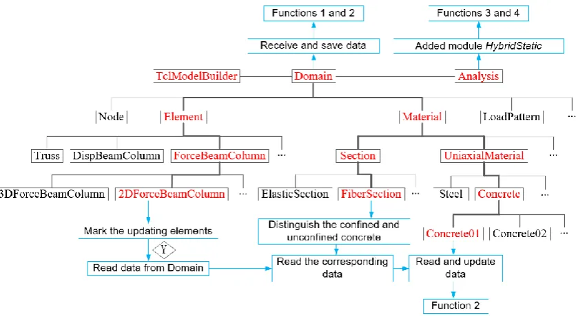
1. The unified constitutive model of unconfined and confined concrete is derived from the existing uniaxial concrete constitutive models by introducing the volumetric stirrup ratio . 2. To solve the problem that the relation of the measurements (force of the specimen of a RC member) and the identified parameters (concrete constitutive parameters) are difficult to analytical expressed, an OpenSees embedded unscented Kalman filter is proposed for parameter identification. To this end, several parts of the OpenSees source codes are developed and modified.
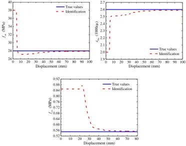
3. The proposed identification method and hybrid simulation based on updating the concrete constitutive parameters are respectively validated through a monotonic loading test on a RC column and a UHS on a RC frame. The results show that the convergence values of each parameter under various experimental cases are close to each other with a small variance, which indicates that the proposed identification method is robust and reliable. Comparing to the standard HS, the accuracy of the NS, hence the UHS, is significantly improved.
Quando la simulazione ibrida (HS) con sottostrutture viene impiegata per valutare il comportamento sismico di una grande struttura complessa, non è realistico testare tutti i componenti che possono presentare una forte non linearità. Quindi, l'accuratezza della sottostruttura numerica (NS) deve affrontare una sfida maggiore. A tal fine, questo documento enfatizzerà il miglioramento dell'accuratezza dell'NS nella simulazione ibrida basata sull'approccio di aggiornamento del modello.
La maggior parte delle simulazioni ibride con l'aggiornamento del modello (UHS) si concentrano sull'aggiornamento dei parametri del modello costitutivo del componente (modello story shear) che porta a errori di modellazione di grandi dimensioni e alle risposte di dettaglio sconosciuto. Inoltre, i modelli costitutivi del componente più ampiamente utilizzati, come il modello Bouc-Wen, sono i modelli in senso stretto perché sono diversi per i vari membri del RC quando la dimensione del componente, le condizioni al contorno, il rapporto di compressione assiale e il volumetrico il rapporto della staffa è diverso da un componente all'altro. Pertanto, sono necessari numerosi parametri per descrivere le relazioni forza-spostamento di diversi componenti, il che porta all'enorme onere computazionale. A tale riguardo, questo articolo propone un nuovo approccio di simulazione ibrido basato sull'identificazione e l'aggiornamento dei parametri del modello costitutivo del materiale. Il lavoro principale e i risultati si concludono come segue,
1. Il modello costitutivo unificato di calcestruzzo non confinato e confinato è derivato dai modelli costitutivi concreti monoassiali esistenti introducendo il rapporto tra le staffe volumetriche. 2. Per risolvere il problema che la relazione delle misure (forza del campione di un elemento RC) e i parametri identificati (parametri costitutivi concreti) sono difficili da esprimere analiticamente, per l'identificazione dei parametri viene proposto un filtro Kalman unscented incorporato di OpenSees. A tal fine, diverse parti dei codici sorgente di OpenSees sono sviluppati e modificati.
3. Il metodo di identificazione proposto e la simulazione ibrida basata sull'aggiornamento dei parametri costitutivi concreti sono rispettivamente convalidati attraverso un test di carico monotonico su una colonna RC e un UHS su un telaio RC. I risultati mostrano che i valori di convergenza di ciascun parametro in vari casi sperimentali sono vicini tra loro con una piccola varianza, il che indica che il metodo di identificazione proposto è robusto e affidabile. Paragonato allo standard HS, l'accuratezza del NS, quindi dell'UHS, è significativamente migliorata.
DEDICATION
1. Z. MEI, B. WU, O.S. BURSI, G. YANG, Z. WANG. Hybrid simulation of structural systems with online updating of concrete constitutive law parameters by unscented Kalman filter[J]. Structural Control and Health Monitoring, 2018, 25(2). (SCI, IF=2.355)
2. Z. MEI, B. WU, O.S. Bursi. Hybrid simulation with online updating: application to a reinforced concrete bridge endowed with tall piers[J]. Mechanical Systems and Signal Processing (SCI, IF=4.116, Under Review)
3. B. WU, Y. CHEN, G. XU, Z. MEI, T. PAN. Hybrid simulation of Frame Structures with sectional model updating[J]. Earthquake Engineering and Structural Dynamics, 2016, 45(8): 1251-1269. (SCI, IF=1.974)
4. B. WU, X. NING, G. XU, Z. WANG, Z. MEI, G. YANG, Online numerical simulation: A hybrid simulation method for incomplete boundary conditions, Earthquake Engineering and Structural Dynamics, 2018, 47(4): 889-905. (SCI, IF=2.355)
ACKNOWLEDGEMENTS
INDICE
CHAPTER
1. INTRODUCTION
1.1 Background, objective and significance of the subject 1.2 Development of hybrid simulation
1.2.1 Overview of numerical integration method
1.2.2 Overview of loading strategies and time delay of compensation 1.2.3 Overview of platform for hybrid simulation
1.3 Development of hybrid simulation with model updating
1.3.1 Overview of constitutive models
1.3.2 Overview of parameter identification method 1.3.3 Overview of hybrid simulation with model updating
1.4 Development of RC continuous rigid frame bridge
1.4.1 Overview of tall piers with thin-walled hollow section 1.4.2 Overview of RC rigid frame bridge
1.5 Main research contents of this subject
2. CONCRETE CONSTITUTIVE MODEL EMPLOYED FOR PARAMTER IDENTIFICATION AND UPDATNG
2.1 Introduction
2.2 Main concepts of this chapter
2.3 Unified constitutive model for unconfined and confined concrete
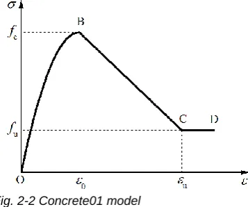
2.3.1 Concrete01 model in OpenSees
2.3.2 Relations of the parameters in the constitutive law of the confined and unconfined concrete
2.3.3 Unified constitutive law
2.3.4 Determination for the initial values of the parameters in the unified model
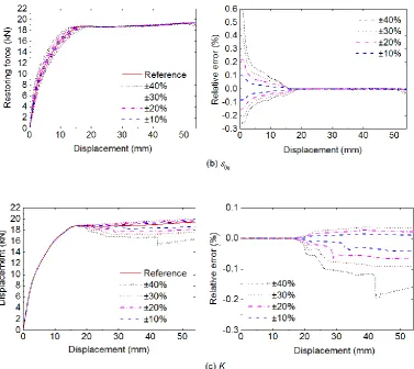
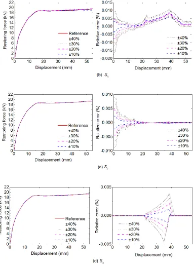
2.4 Sensitivity analysis of the concrete constitutive parameters
3. METHOD FOR INDENTIFICATION OF CONCRETE CONSTITUTIVE PARAMETER 3.1 Introduction
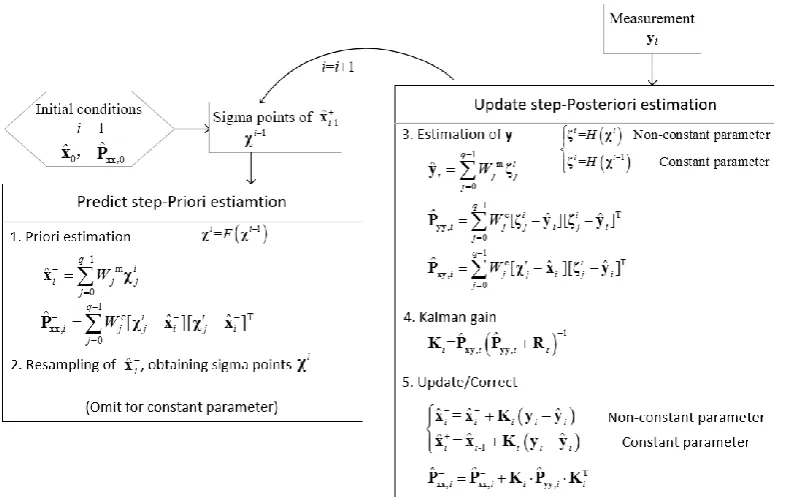
3.2 PRINCIPLE OF UNSCENTD KALMAN FILTER
3.2.1 Brief introduction of Kalman filter 3.2.2 Principle of unscented Kalman filter 3.2.3 Deterministic sampling and its precision
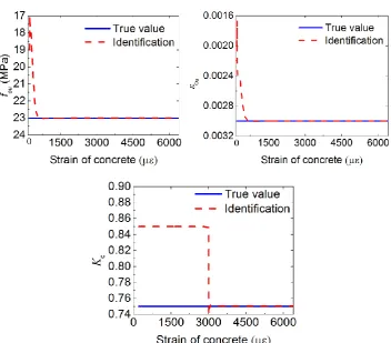
3.3 Parameter identification: Case 1, measurements – concrete stresses
3.4 Parameter identification: Case 2, measurements – restoring forces of RC members
3.4.1 Theory and the programmatically implementation 3.4.2 Numerical validation
3.5 Convergence of unscented Kalman filter
4. EXPERIMENTAL VALIDATIONS 4.1 Introduction
4.2 Validation of the parameter identification method
4.2.1 Testing arrangement 4.2.2 Results
4.3 Validation of the hybrid simulation with updating the concrete constitutive parameters
4.3.1 Platform of hybrid simulation 4.3.2 Testing arrangement
4.3.3 Results
5. HYBRID SIMULATIONS ON A RC CONTINOUS RIGID FRAME BRIDGE 5.1 Introduction
5.2 Engineering background
5.3 Finite element model of the bridge modelling in OpenSees
5.3.1 Refined element model 5.3.2 Simplified element model
5.4 Testing arrangement
5.4.1 Testing scheme
5.4.2 The physical substructure 5.4.3 Loading and observing scheme
5.4 Hybrid simulations
5.5.1 Study cases
5.5.2 Initial values of the parameters 5.5.3 Results of the parameter identification 5.5.4 Results of the hybrid simulations
1
.
INTRODUCTION
1.1 Background and Motivation
Enormous human casualties and economic losses have been brought to human beings by earthquake disaster. China has hit many earthquakes of magnitude 7.0 and above, such as the Yushu Earthquake, the Wenchuan Earthquake, the Ya'an Earthquake, and Yutian Earthquake since 2000. Among them, the most serious is the Wenchuan earthquake which is a destructive shallow earthquake at a depth of 14 km with the magnitude of 8.0. In this disaster, 69,227 people were killed and 17,923 people were missing, with a direct economic loss of 845.2 billion yuan. In order to alleviate the losses caused by seismic disaster, a great deal of researches have been conducted on earthquake monitoring, mechanism of earthquake formation, structure anti-seismic theory, structural post-earthquake recoverability and many earthquake-related sciences. Based on the statistics of post-earthquakes losses, we can see that the damage and collapse of buildings, bridges and other structures are the most important causes of casualties. Fig. 1-1 shows typical failure modes of reinforced concrete structure after earthquake. In order to improve the safety of structures, it is very important to study the strong non-linear behavior and seismic performance of components and structures under earthquake loading so as to master the dynamic catastrophic process of structures. Among others, structural seismic test is important means to study the seismic performance of structures, which can not only verify the theoretical results, but also find new problems so as to develop and perfect the theory.
Laboratory seismic testing methods are divided into quasi-static test, pseudo-dynamic test, shaking table test (Qiu et al., 2000). The quasi-static test method is the most widely used seismic test method at present, which forces the specimen to undergo the entire process from to the final destruction through the ow-frequency cyclic loading. In this way, the carrying capacity, deformation capacity and energy dissipation capacity and damage characteristics of the specimen can be obtained. However, this method cannot provide the dynamic response of the structure under earthquake. Shaking table test is the most direct method to study the seismic performance of structures in the laboratory. It can reproduce the dynamic response and failure mode of the structure under earthquake. However, the size of the target structure tends to be severely restricted due to many factors such as laboratory space, size and bearing capacity of vibrating table, and the experimental budget. If a scaled model of the target structure is used in shaking table test, it will face the problem that the dynamic similarity cannot be satisfied. This leads to that the results of the scaled model test are difficult to extend to the prototype structure (Qiu et al., 2000; Zhang, 2010).
Pseudo dynamic test is also called the hybrid simulation, whose main idea is to solve the motion equation of the structure by computer. In the equation, the inertial force and the damping force which are easy to simulate are numerical simulated by the computer; while the restoring force of the structure which is hard to accurately simulate is experimentally simulated. In each integral step of the process, the solved displacements are static loaded on the specimen of the structure, then the restoring forces of the specimen are real measured and feedback to the equation of motion in the computer. Therefore, combing the advantages of the static loading method and the development of computer, the seismic effect can be considered through the pseudo dynamic test method. Because of this, hybrid simulation has gradually attracted the attention of engineers and scholars since it was proposed, and has been promoted and applied.
With the development of control science, computer and network technology, pseudo dynamic test method have been gradually developed such as full scale structure pseudo dynamic test, substructure pseudo dynamic test and real-time pseudo dynamic test. For large complex structures, it is not easy to implement pseudo-dynamic test on a full-scale structure due to the limitation of the capacity of loading equipment and experimental budget. Therefore, the substructure pseudo dynamic test method that can realize large-scale or even full-scale specimen is gradually developed. Substructure pseudo dynamic test separates the structure into numerical substructure (NS) and experimental/physical substructure (PS). The key components in the structure that may experience nonlinearity are isolated and loaded in the laboratory as the PS, and the remainder are analyzed by numerical simulation in a computer, i.e. the NS. As well, the motion equation of the structure is solved by the computer. In the process, the compatibility of deformation and balance of force are ensured. During the substructure pseudo dynamic test, the motion equation is solved by the coordinator /computer, the solved displacements are sent to both the NS and the PS, and then the numerically and experimentally simulated restoring forces are returned by the NS and the PS respectively to the coordinator for solving the equation at next integral step till the end of the seismic loads. The advantage of substructure pseudo dynamic test is that the testing target is only a single component or a part of the whole structure, which makes the large-scale and even full-scale specimen can be realized.
take out all the key components to be experimentally tested as the PS. Most of the key components that may experience nonlinearity, inevitably, need to be simulated as the NS. So, the accuracy of the NS should be pay more attention to. In order to improve the accuracy of the numerical model, scholars have been made a lot of efforts by giving more reasonable assumptions, proposing more accurate and stable numerical integration method, proposing more types of finite element (FE) units applicable to different components and structures, and proposing more accurate constitutive models to simulate the behavior of components, sections and materials. For pseudo dynamic test, the NS is built based on the existing FE principles, integration methods and constitutive models. Therefore, the emphasis of this paper is how to improve the accuracy of numerical analysis after the NS is established, and thus the reliability of the whole hybrid simulation. Model updating proposed in the 1990s to improve the simulation accuracy of numerical models of mechanical and building structures can solve this problem well (Friswell & Mottershead, 1995; Friswell & Mottershead, 2001).
The essence of model updating is to optimize the parameters in the numerical model by experimental data to reduce the errors caused by the unreasonable assumptions and errors in the numerical model and finally to minimize the specific errors between the calculated numerical model and the observed data. That is, the numerical model (which can directly the force-displacement behavior of the component or structure, or the material constitutive models used in the FE model) can be updated and improved through the experimental data. Aiming at improving the reliability of hybrid test, this paper combines the hybrid test with the model updating method, and proposes a new hybrid test method based on identifying and updating the parameters of material constitutive models. The proposed updating hybrid simulation is verified by numerical and experimental ways, and finally is applied to a thin-walled high-pier reinforced concrete continuous rigid-frame bridge to simulate the seismic behavior of the bridge. It is expected that this study will be helpful for the development of structural hybrid simulation.
1.2 State of Art for Hybrid Simulation
Fig. 1-2 Schematic diagram of hybrid simulation
The inertia forces and damping forces in the equation are simulated by computer, whilst the structural restoring force is obtained by experimentally loading. After receiving the feedback forces, the computer proceeds to solve the equation at the next step by a given numerical integration method and sends the solved displacements to the specimen. The cycle will go on till the end of seismic loads.
With the enlargement and complexity of civil engineering structures, the existing conditions of loading equipment and sites are difficult to meet the requirement of the hybrid simulation with large-scale specimen when the whole structure is taken to be the target structure. Therefore, the substructure pseudo dynamic test was proposed in the mid-1980s (Dermizakis & Mahin, 1985) and gradually developed. In the substructure hybrid simulation, the structure was divided into two parts: the experimental/physical substructure (PS) and the numerical substructure (NS). The solved displacements were sent to both the PS and the NS, as shown in Fig 1-3. Then, the substructures return the restoring forces Rn(t) (NS) and Re(t) (PS) to the computer, respectively,
after calculation or loading. That is, the R(t) is the sum of Rn(t) and Re(t).
Fig. 1-3 Schematic diagram of hybrid simulation with substructures
hybrid simulation cannot meet the needs.
In order to avoid the waste of existing laboratory resources and the repeat of laboratory construction, hybrid simulation are gradually expanding in the space domain. By transmitting the data through networks, several specimens can be loaded simultaneously in different laboratory located in different regions. In this way, the advantages of different laboratory resources was integrated to complete the hybrid simulation of large complex structures with multi large-scaled substructures. This is called distributed hybrid simulation, also known as international collaborative hybrid simulation (Sugiura et al., 1998; Takashi et al., 2005).
The US (NEES-Network for Earthquake Engineering Simulation) (Pauschke et al., 2003; Spencer et al., 2004), China (NetSlab-Network Structural Laboratories) (Fan, 2010) and Korea (KOCED collaboratory program) (Kim, 2014) have completed the resource integration of several local laboratories.
The following will address some key issues of hybrid simulation including the solution of motion equation, the nonlinear control, delay and compensation of actuators, and the platform for hybrid simulation.
1.2.1 Numerical integration method
In the hybrid simulation, the motion equation of the structure is discretized in time domain by numerical integral method and the displacements of the structure at each time step is obtained. Numerical integration method can be divided into explicit and implicit algorithms. If the unknown quantities (displacement, velocity acceleration) can be expressed by the known quantities at current and previous steps, then it is the explicit algorithm, otherwise it is implicit algorithm. The advantage of explicit algorithms is that they do not require iteration, while the disadvantage is that most of them are conditionally stable and are limited by the integral step-size. Among others, the central difference method is the most classic algorithm, and is early and widely used in the field of hybrid simulation. Taniguchi et al. completed the pseudo-dynamic test of a one-bay one-story frame structure using center difference method in 1980 (Taniguchi et al., 1980). Nakashima discussed the accuracy of the central difference method and the stability margin of the method for damped and un-damped systems (Nakashima, 1985 part1 and part2). The advent of real-time hybrid testing puts forward new requirements for the central difference method. Wu et al. analyzed the accuracy and stability of the method in real-time substructure hybrid simulation (Wu et al., 2005).
real-time hybrid simulation (Wu et al., 2006).
For implicit methods, the advantage is that they are unconditionally stable for linear structures. The disadvantage is that there exists iterations in the process, which results in increased computational time and affects the analysis results of components with strong nonlinearity. In addition, the loading and unloading behavior caused by iterations can lead to inaccurate results. Newmark- family and the -α family are two kinds of the most widely used implicit methods. The accuracy of the Newmark- family is mainly controlled by the two parameters and γ. When = 1/4 and γ = 1/2, it is the commonly used average acceleration method; when = 1/6 and γ = 1/2, the linear acceleration method; when = 0 and γ = 1/2, the central difference method. Newmark (Newmark, 1959) showed that the Newmark- family is unconditionally stable to the linear systems when γ≥1/2 and = 0. Hughes (Hughes, 1977) pointed out that the average acceleration method can converge for nonlinear dynamical systems; and the convergence rate of displacement and velocity are the same. Deng (Deng, 2011) studied the stability of averaged acceleration method for nonlinear structures; and results shown that it may change to conditionally stable for dissipative structures. Though Newmark- method can eliminate the high frequency response, it also filter out a lot of low-frequency responses of structures. This may decrease the analysis precision. Based on Newmark- method, -α family introduced a new parameter α to filter out the high-frequency response caused by the finite element discretization, without decreasing the low-frequency response of the structure itself. If the parameter α is introduced into both the damping and stiffness terms, the method is the HHT-α method (Hilber et al., 1977); if it is only introduced into the mass term (inertial force), it is the WBZ-α method (Wood et al., 1980). Combining the HHT-α and the WBZ-α, Chung and Hulbert proposed a generalized -α method which can give the optimal combination of high-frequency and low-frequency dissipation (Chung & Hilbert, 1993).
The unconditional stability of the classical implicit integration method is limited to the linear system. When considering the nonlinearity of the structure, it may fail. Therefore, the method still possess unconditional stability for nonlinear systems is required, that is the energy method. Constraint energy momentum algorithm (Hughes et al., 1978) is a method that, based on average acceleration method, considers energy conservation through the Lagrange multiplier to correct the dynamic balance equation. In the energy-conserving integration method, the discretization is at a local level (the level of material or local coordinates) instead of the global discretization at global level used in traditional integral methods (Sim & Tarnow, 1992). However, energy-conserving integration method can only achieve energy balance when structures are elastic. The energy consistent integration method is proposed to solve the problem when structures goes into elastic-plastic phase. Crisfield and Shi proposed a uniform energy integration method based on truss elements (Crisfield & Shi, 1992). However, this method considered only the geometrical nonlinearity, not including the nonlinearity in material. Pan et al. (Wu et al., 2016; Pan, 2016) made a series study on the energy consistent integration method considering both geometrical and material nonlinearity, and applied the proposed method in hybrid simulation.
Loading control method directly influences the realization of boundary conditions of specimens .It is the main part of hybrid simulation, and affects the accuracy of hybrid simulation to a large extent. Therefore, the loading control method has received a great deal of attention.
The servo -hydraulic actuator is most widely used for loading on specimens in hybrid simulations. A good strategy for actuator control will be helpful to reduce the effects of actuator delay so as to improve the accuracy and stability of hybrid simulation. Combining the PID control method and feedforward compensation method, Jung proposed a method that take into account the nonlinearity both in the oil flow of the actuator and the displacements (Jung, 2005). Wang designed an internal model control strategy and proved that this method has better robustness than PI control (Wang, 2012). Phillips and Spencer proposed a model-based approach to multi-actuator control which considered both the dynamic behavior of the actuators and the dynamic coupling between actuators (Phillips & Spencer, 2013).
According to the different control objectives, loading scheme can usually be divided into displacement control, force control and force-displacement mix control. Displacement control is a relatively mature and widely used method in hybrid simulation (Drury et al., 2002; Wagg & Stoten, 2010; Bonnet et al., 2010), because the displacement is just the solved quantity from the motion equation by computer. However, the increment of displacement for each integral step may be very small when the stiffness of specimen is large, making it difficult to guarantee the loading accuracy. At this point, force control is more applicable. In force control methods, the force command is calculated by converting the displacement command received from the computer. Sivaselvan et al. obtained a force command by introducing a flexible mechanism between the actuator and the structure to be excited (Sivaselvan et al., 2010). Kim proposed a Krylov subspace-based compatibility method to convert displacement commands to force commands and proved that the force command obtained by this method is more accurate than by traditional tangent stiffness identification (Kim, 2011). Pan et al. adopted a force-displacement mix control to complete a hybrid simulation, where the displacement control method and force control method are used to control two separate actuators connected to one specimen (Pan et al., 2010). In the meantime, the switch control strategy was adopted in the axial direction, where force control is used for pressing process, the displacement control is for pulling process. Tan et al. proposed a displacement outer loop and force inner loop control method for hybrid simulation (Tan et al., 2012). Zeng et al. developed a two loop feedback control method to keep the axial force constant and extended to multiple actuators coupled control (Zeng et al., 2014).
Horiuchi et al. (Horiuchi et al., 1999) predicted the current step acceleration by third-order polynomial linear extrapolation by assuming linear changes in acceleration over time, and then predicted the delay compensation for the next step using the predicted acceleration and the velocity at the current step. Zhao et al. applied a first-order phase-lead network to reduce actuator delay (Zhao et al., 2003). Chen simplified the model of the servo-hydraulic system based on the first-order discrete transfer function and then compensated the actuator lag by using the inverse model (Chen, 2007). Using known structural characteristics (mass, stiffness and damping matrix) and loads, Carrion and Spencer proposed to predict actuator input displacements based on the model response to compensate the time delay (Carrion & Spencer, 2008). Phillips and Spencer developed a feedforward time-delay compensation method based on the transfer function of test structure and the model of servo-hydraulic actuator (Phillips & Spencer, 2012). Wu et al. proposed a method based on upper bound delay to compensate for the displacement and validate it with a single degree of freedom system and the five-degree-of-freedom system (Wu et al., 2012). Results shown that this method is superior to the traditional method.
1.2.3 Platform of hybrid simulation
The software platform of hybrid simulation is a necessary factor for developing real hybrid tests. In order to reduce the application threshold of hybrid simulation and further popularize the testing method, many efforts have been put into the software platform.
OpenFresco is an open source hybrid testing platform developed by Schellenberg et al. at the University of California, Berkeley (Schellenberg et al., 2006; Takahashi & Fenves, 2006). When using OpenFresco, the motion equation of structure is solved in the finite element (FE) software where the numerical substructure (NS) is established. OpenFresco is only responsible for the data transfer between the NS and the experimental/physical substructure (PS). It is note that a numerical element of the PS should be included as well in the FE model of the whole structure. Nevertheless, the restoring force of this virtual element for the PS is actually measured from the specimen, i.e. the PS. The "test cell" provided in OpenSees is precisely the element developed for this purpose. OpenFresco now offers interfaces for the FE software including OpenSees, ABAQUS, ZeusNL, and LS-Dyna, and for testing control systems including MTS, dSPACE, LabView, SCRAMNet and xPCTarget.
UI-SimCor (Kwon et al., 2006) is a platform developed by Kwon et al. at the University of Illinois at Urbana-Champaign based on the Matlab scripting language. Unlike OpenFresco, UI-SimCor is not only responsible for data transmission, but for solving the motion equation of structure with the built-in HHT-α numerical integration method. Currently UI-SimCor provides interfaces for OpenSees, Zeus-NL, ABAQUS and FedeasLab. It communicates with testing control systems through TCP/IP, LabVIEW OR NHCP (NEES Hybrid Communication Protocol).
NetSlab platform was developed by Guo et al. at Hunan University for applying the distributed hybrid simulation. This platform was later jointly improved by Hunan University and Harbin Institute of Technology. NetSlab includes the part for single degree of freedom structure (Fan et al., 2009) and as well the part for multi-degree-of-freedom structure (Guo et al., 2011).
al., 2010). On this platform, each substructure is treated equally, that is, the motion equation of each substructure is established respectively. Then the dynamic characteristics of the substructures are condensed to the boundary interface and the compatibility of the boundary conditions is responsible by the coordinator.
Hytest platform was developed by Wu et al. at Harbin Institute of Technology, which supports both standard hybrid simulation and model-updating hybrid simulation (Yang J, 2014; Yang G, 2017), and supports both local and distributed hybrid simulation. Similar to UI-SimCor, the Hytest is responsible for solving the structural motion equations as well as the data transfer between the substructures and the updating module. Currently, Hytest supports OpenSees and ABAQUS FE software and MTS control system.
1.3 State of Art for Hybrid Simulation with Model Updating
For large complex structures, such as high-rise buildings, long-span space structures, and long-span bridges, the number of key component which may exhibit strong nonlinearity under earthquakes will largely increase. When hybrid testing method is employed for investigating the seismic behavior of such structures, only one or several, but not all, of the key components can be studied experimentally as the PS due to the limit budget, laboratory sites and loading equipment. The rest key components will be numerically simulated as the NS. So, this raises the requirements for the accuracy of the numerical models of structural members with strong nonlinearity. Model updating is an effective way to improve the accuracy of numerical models, i.e. the NS in hybrid simulation. Model updating is to use the experimental data to identify/optimize the model parameters. That is the analysis results of the numerical model with these optimal parameters have a high matching with the experimental results, with a minimum error under certain criterion. By introducing the model updating into standard hybrid simulation, the parameters are optimized based on the testing data of the PS, then the optimal parameters are updated to the NS to improve the accuracy of numerical simulation, and hence the accuracy of the hybrid simulation.
of such models and their parameters is clear and easy to understand and applied.
1.3.1 Constitutive model of beam-column element
Constitutive model (CM), also called constitutive equation, is a mathematical model that reflects the macroscopic nature of matter. In civil engineering, a CM generally reflects the stress-strain relationship of a material. In order to establish a contrast relationship with the material CM, scholars have gradually put forward the concept of section CM and component CM. The section CM reflects the relationship of the restoring force (axial force and bending moment) and the curvature in the section, whilst the component CM reflects that of the restoring forces and displacements of the structural component. Force, bending moment and stress can be collectively referred to as generalized force, while displacement, curvature and strain can be collectively referred to as generalized deformation. Therefore, the constitutive model can be understood as the relationship of the generalized force and the generalized deformation.
Over years, several methods have been developed for modelling structures and representing their nonlinear behavior under earthquake excitation. These approaches can be classified into three main categories: global model methods, structural FE model methods and continuum FE model methods (Taucer et al., 1991), as shown in Fig. 1-4. Global model method is simplest one, assuming that the material nonlinearities concentrate only at global degrees of freedom. That is to say, the force-displacement relationship at each degree of freedom is described by a nonlinear
Fig. 1-4 Categories of modelling a structure
accurate simulation of the nonlinear behavior, however, they are the most sophisticated and time consuming. Among the three, the structural FE models are the most widely used approach because they can meet the requirements of both the accuracy and computational efficiency. The component CMs are applicable to the global models and concentrated FE models, the section CMs are for the distributed FE models, and the material CMs are for the distributed FE models and the continuum FE models.
For the component CM, Taucer et al. summarized a number of component CMs including the models considering stiffness degradation, both the stiffness and shear degradation, the rate-based model (Taucer et al., 1991). Ibrarra et al. proposed the Ibrarra-Krawinkler model, which takes into account the stiffness and strength deterioration as well as pinching (Ibrarra et al., 2005). Ozcebe and Saatcioglu proposed a hysteretic shear model for reinforced concrete members (Ozcebe & Saatcioglu, 1989). Takizawa and Aoyama proposed a model for RC structures which contains the biaxial effects (Takizawa & Aoyama, 2010). Among others, the bilinear model and Bouc-Wen model (Bouc, 1967; Wen, 1976) are the most commonly used models in model updating of hybrid simulation.
For the section CM, there are three types of moment-curvature models that used in early study of the behavior of RC members: i) Ramberg-Osgood model (Ramberg & Osgood, 1943) came from the restoring force-displacement model of the metal; 2) the bilinear model (Gu, 2002); a bilinear-model-based section model proposed to consider both the effects of cumulative damage of concrete during reverse loading and the stiffness degradation during unloading process (Clough, 1962). To more accurately simulate the moment-curvature relation of concrete, a three-linear model and a four-linear model were proposed to represent the continually varying stiffness and energy absorbing characteristics of concrete (Takeda, 1970). Park and Young proposed a section CM that takes into the account the pinching effect generated from shear failure (Takeda & Young, 1987). Lu et al. proposed a comprehensive section CM including 10 parameters, which can be used for simulating the behavior of bending failure, shear-bending failure and shear failure (Lu et al., 2015). Wu et al. proposed a section CM considering the coupling of axial forces and bending moments, and verified the model by numerical analysis (Wu et al., 2016).
parameters to consider the influence of strain rate on confined concrete. Compared with the Kent-Park model, this model assumed that the stirrups enhanced the concrete strength and ductility to the same extent. Mander et al. proposed a new mathematic model for concrete (Mander, 1983; Mander et al., 1988), and he believed that the reinforcement of stirrup to the concrete ductility is much larger than that to the strength of concrete. Based on the Kent-Park model, Yassin [94] considered the tensile behavior of the concrete through a two-branch straight line. As the increasing of applying the FRP, the CMs of FRP confined concrete were gradually studied (Gallardo-Zafra & Kawashima, 2009; Megalooikonomou et al., 2012; Papavasileiou & Megalooikonomou, 2015). Due to the complexity of concrete material, no CM has so far been totally accepted for describing the mechanical properties of concrete material.
1.3.2 Parameter identification
System identification is to select a best model from a given set of models. This model, according a certain criteria, should be the one whose outputs can best fit the existing data. That is, if S is the system to be identified, and a model M is preset. The condition that M can be used for expressing the system S is that the error of the outputs provided by S and M satisfies the requirement according to the certain criteria. If the condition is not met, the M must be modified till the error is small enough. This optimization process is the system identification.
On the basis of the knowledge of the system to be identified, the system identification algorithm can be divided into nonparametric identification method, i.e. the ‘black box’ method, and parameter-based identification method, i.e. the ‘gray box’ method. The modern ‘black box’ methods, which mainly includes neural network algorithm, fuzzy logic method, genetic algorithm and particle swarm optimization, do not need to have a priori knowledge of the system S to give a preset model M. However, the physical meaning of the model of this kind of algorithm is not clear enough, which makes it difficult to be applied and promoted in the field of engineering. Moreover, the computation burden of these methods is large. In the ‘gray box’ methods, a relative accurate model with a certain number of parameters should be preset, and the parameters are the targets that need to be optimized according to a determined criteria.
According to the preset model, parameter identification can be divided into linear and non-linear identification methods. The preset model can be used to describe i) the relation of the parameters at the current step and those at the next step, which is called state equation/model; and ii) the relation of parameters and measurements, which is called measurement equation/model. If both the state equation and measurement equation are linear, the problem belongs to the linear estimation, otherwise, the nonlinear estimation.
as well as larger storage capacity is needed. With this respect, online identification algorithm is more applicable, where only the data measured at the previous step are needed. The online methods need small storage capacity providing a higher calculation efficiency.
As mentioned above, there are many different identification methods for various needs. The following contents will focus on the methods which are commonly used in the field of civil engineering.
1.3.2.1 Least square method
Least-squares estimation (LSE) is one of the most widely used methods in civil engineering. The basic principle of the method is to obtain the optimal estimation by minimizing the sum of squares of the residuals of measurements. The residual of measurement is the difference between the estimated and the measured value of the output (observation). When the credibility of each observation is different from another, a weighted least-squares estimation can be employed by weighting each measure data. The LSE belongs to offline region. In order to realize online estimation, recursive least-squares method was developed on the basis of the LSE. Later, augmented least squares, generalized least squares, and compensated least squares are gradually developed for the estimation problem with colored noise.
The LSE is widely used in civil engineering, such as the estimation of structural stiffness and damping (Caravani & Thomson, 1974; Agbabian et al., 1991; Loh & Tou, 2010), the identification of the location and level of structural damage (Chen & Bicanic, 2000; Yang et al., 2006), the identification of constant as well as time-varying parameters (Yang et al., 2006; Yang & Lin, 2004). However, the LSE can only deal with the problem belongs to linear estimation whose state equation and measurement equation are linear. It cannot be directly applied to identify the parameters of nonlinear models. For example, the identifying the parameters of a nonlinear restoring force model such as the Bouc-Wen model, the model should be linearized first. Then the LSE can be implemented. Zhang et al. successfully implemented the LSE to identify parameters of Bouc-Wen model by linearizing the equation of the restoring force and parameters using implicit integration rules (Zhang et al., 2011). Wang et al. achieved the linear measurement equation by expressing the restoration force as the combination of basic functions considering the parameters as coefficients, and identified the parameters of both the bilinear model and the Bouc-Wen model using LSE (Wang et al., 2011). However, the process of linearizing the nonlinear model is sophisticated and the precision of estimation is not good enough.
1.3.2.2 Kalman Filter
Where x is the state vector to be estimated, y is the measurements. For linear systems, the estimation provided by KF is just the optimal estimation of Bayesian, with only the need of calculating the first two moments of the variables x and y.
Fig. 1-5 shows the basic principle of KF. As shown that, a predict step was first implemented before the final correction of the variable x based on the observation residuals. The priori estimation is obtained in this predict step based on the state equation, which makes it enable to estimate the time-varying linear system. As can be seen that the predict step can be omitted when the parameters being identified are constant. The parameters can be optimized using only the observation-correct step with the measurement and its estimation. For constant parameter estimation, the KF returned to the recursive LSE.
Fig. 1-5 Schematic of Kalman filter
1.3.2.3 Extended Kalman Filter
Extended Kalman Filter (EKF) is proposed to solve the problem of nonlinear estimation that KF cannot solve. The main idea of EKF is to linearize the nonlinear system in the first-order, and continue to use the linear recursive framework of KF. During the linearization process, errors were introduced, making EKF a suboptimal estimation.
the frequency and damping of structures under earthquakes. Yang et al. proposed an adaptive EKF to implement the online identification of structural parameters (Yang et al., 2006). Zhang et al. used EKF to identify the parameters of the inelastic structures that considered pinching and degradation in their hysteretic traces (Zhang et al., 2010). Li et al. proposed to combine the EKF with wavelet multiscale decomposition to identify model parameters of nonlinear structures (Li et al., 2013). Astroza et al., based on EKF, identified the parameters of the steel model used in fiber element model and achieved a good result (Astroza et al., 2015). However, EKF needs to calculate Jacobian matrices at each step, which leads to an increasing computation and even results in the system instability for a strong nonlinear problems. It is found that EKF can give a reliable estimation only when the system is linear or weak nonlinear. Furthermore, the linearization process requires the state and measurement equations to be differentiable, making the implementation of EKF difficult. In addition, the initial values of the parameters need to be identified will affect the EKF estimation. The incorrect initial values will not only lead to inaccurate estimation, but may even cause the results to divergence.
1.3.2.4 Unscented Kalman Filter
In order to better solve the problem of the identification of nonlinear systems, Julier et al. proposed the unscented Kalman filter (UKF) based on KF (Julier et al., 1995; Julier & Uhlmann, 1996). Later, other researchers (Wan & Van Der Merwe, 2000; Van Der Merwe & Wan, 2001) and Julier himself (Julier, 2002; Julier & Uhlmann, 2002) conducted an in-depth study of the UKF method to further improve the accuracy and stability of the algorithm. As the same with EKF, the UKF also built based on the linear recursive framework of KF to solve the nonlinear optimization problem. But there is no need to linearize the nonlinear systems anymore in the UKF. Instead of approximating the system by linearization, the UKF use the deterministic sampling methods and the unscented transform to approximate the first two moments, the conditional expectations and the variances of the random variables which includes both state variables need to be identified and the measurements. In the process, there are two approximations in the process of UKF (Mei et al., 2018), i) continue to use the recursive framework of KF for linear system estimation. That is, the KF can provide an optimal estimation for linear systems by using the first two moments of the state variables and the measurements. However, the first two moments are not enough to give the optimal estimation for nonlinear systems; ii) the approximations of the first two moments. Therefore, the estimation provided by UKF is not the optimal one either. However, the UKF process does not need Jacobian matrices calculation and can be used for strong nonlinear systems with a more stable and accurate estimation (Mariani & Ghisi, 2007).
sensors for velocity and acceleration (Eleni et al., 2009). The results shown that UKF has higher accuracy than PF as well as lower computational burden. In 2010, Chatzi et al. (Chatzi et al., 2010)] used the UKF method to identify the parameters of a nonlinear structural model based on the experimental data in provided in reference (Tasbihgoo et al., 2007). In 2013, Tao used the UKF method to online identify the shear-type nonlinear substructure and its seismic damage (Tao, 2013). Song and Dyke applied the UKF to the hybrid simulation to identify the parameters of the models of MR damper and the steel frame structure (Song & Dyke, 2013). Then the convergence value of the parameters were used to update the numerical model, which validate the effectiveness of the model updating. In 2014, Wu and Wang proposed a constrained unscented Kalman filter and applied it to identify the parameters of Bouc-Wen model (Wu & Wang, 2014).
1.3.3 Model updating hybrid test
The model updating method is an effective method to improve the accuracy of the numerical substructure (NS) in hybrid simulation by making full use of the data measured from the experimental/physical substructure (PS). According to the identification methods, the model updating of hybrid simulation can be divided into two categories, the non-model-based updating method and the model-based parameter-updating method. Due to the clear physical meaning and computational efficiency, the model-based parameter-updating methods are extensively applied. Depending on whether the parameters are being updated during the experiment, model updating can be divided into offline and online methods. Offline model updating refers to that the parameters are identified and updated after the experiment, then the model that has been updated with the identified parameters is used for numerical analysis. Hybrid simulation requires online updating where the parameters can be identified and updated at each step during the test. The schematic of the hybrid simulation with online model-based parameter updating is presented in Fig. 1-6.
Fig. 1-6 Schematic of hybrid simulation with and without model updating
equations of the structure and sending the calculated displacement u to both the PS and the NS. The PS and NS send back the measured and numerical restoring forces, Re and Rn, respectively.
Then after receiving the forces, the coordinator solves the equation at next the next time step and the hybrid test goes into next step. By adding a module of model updating which is the part with gray dashed line shown in Fig. 1-6, the hybrid simulation with model updating (UHS) can be achieved. A numerical model of the PS, which includes the preset constitutive model, should be built to obtain the estimation of measurement, Re’ in this paper, for parameter identification.
According to a certain criteria, the optimal parameters which minimize the residual of measurement and its estimation, Re and Re’ in this paper, can be provided by the module of
parameter identification. Then the optimal parameters will be updated to the NS with the same preset constitutive model. Note that, these optimal parameters are those for the preset constitutive model of the PS, not for the NS. So, these parameters can only be used to update the NS’s components that employed the same preset constitutive model with the PS. For the preset constitutive model, it can be a hysteretic component model that directly expresses the force-displacement relationship of the structural member, a section constitutive model that describes the moment-curvature relationship of the section, or a material constitutive model that presents the stress-strain relationship. In the UHS, the coordinator is also responsible for solving the motion equations to obtain the displacement and transmitting the data. The calculated displacements are sent the PS, the NS and as well the identification module. The PS is then loaded and the measured restoring force is sent to the coordinator and the identification module. In this process, the identification module and NS are in a state of waiting. After receiving the measurement from the PS, the identification module executes the optimization process in which the NS is still in waiting state. After the optimal parameters are received from the identification module, the parameters in the preset constitutive model of the NS are firstly updated and then the computing of the NS is proceeded and the simulated restoring forces are send to the coordinator. Finally, the coordinator goes into the next step and solve the motion equation at next time step.
of the PS for parameter identification was the same as that of the NS. Therefore, the parameters optimized using the ‘measured’ data of PS were updated to the hysteretic model which is for the NS in the process of the hybrid simulation. In 2010, Zhang used the LSE to identify the parameters of the ideal elastic-plastic model, the bilinear model and the Bouc-Wen model, and applied them to realize the adaptive hybrid simulation (Zhang, 2010). Wang et al. applied the LSE (Wang et al., 2014) and the UKF (Wang et al., 2013) to a hybrid simulation of a two-story braced frame. The brace of the base-story frame was taken as the PS, the remainder was isolated to be the NS. The numerical model of the PS was the same as that of the brace in the secondary-story frame. During the test, the parameters of the model of the PS were identified using the restoring force of the PS, and updated to the model of the brace in the secondary-story frame. Subsequently, Wang and Wu proposed a new constrained UKF algorithm by modifying the sampling points, and applied it to a UHS (Wang & Wu, 2013). In 2013, Kwon and Kammua proposed a new idea for model updating (Kwon & Kammua, 2013). This method assumes that the model to be optimized is a weighted linear superposition of several models, and the parameters to be identified and updated are the weight coefficients for the linear superposition. The results shown that the updated model can well simulate the hysteretic behavior of PS. In 2014, Hashemi et al. carried out a UHS of one-bay one-story frame based on the OpenFresco software platform (Hashemi et al., 2013). In this test, the left column is the PS whose preset component constitutive model, the Bouc-Wen model, is the same as that for simulating the right column, i.e. the NS.
1.4 State of Art for RC Continuous Rigid Frame Bridges with Hollow Thin-walled Tall Piers
Bridges are great important parts of the lifeline projects. Some of them, which were built in the earthquake-prone areas, faces great potential threat. Once the bridge is destroyed, the traffic will be interrupted, which hinders the rescue work after the earthquake. Therefore, it is essential to study the seismic behavior of various types of bridges.
The RC continuous girder bridge is one of the most early and widely used bridges in the world. Due to the absence of expansion joints, such bridges have a good smoothness for driving. However, this type of bridge needs bearings whose maintenance cost is high, and the structural system needs to be converted after the bridge is closed. In the 1960s, with the improvement of construction technology, RC continuous rigid frame bridges gradually developed and applied. They not only maintains the advantage of continuous beam bridge without expansion joints for good vehicle running, but also maintains the advantage of no support and no system conversion for T-shaped rigid frame bridge.
The pier and beam of continuous rigid frame bridges are consolidation, making the integrity and seismic performance of this kind of bridge are good. Comparing to T-shaped frame bridge, the flexible/tall piers are commonly used for continuous rigid frame bridge, which may reduce the displacement at the pier top produced by shrinkage and creep of concrete as well as the temperature. A hollow cross-section is particularly common for the design of RC tall piers since it can provided provide sufficient stiffness with a reduced cross-section area which brings the benefit of cost savings, and the reduction of pier mass resulting in the attenuation of the relevant seismic responses. Therefore, the continuous ridge bridges with long span and hollow-section tall piers have been widely constructed, especially in mountainous area in southwest China due to its good spanning ability to cross deep canyons (Du et al., 2011). However, there is still no clear definition on with how much height the pier belongs to the tall pier. China Highway Bridge Seismic Design Rules (JTG / T B02-01-2008) requires that the bridge with pier height of more than 40 meters should be conducted special study. So, a bridge with a pier height greater than or equal to 40 meters is considered as a tall-pier bridge in this study. The representative tall-pier RC continuous rigid frame bridges are listed in Table 1-1.
presented from several aspects of the experimental and numerical simulation of thin-wall hollow-section tall piers, and the hybrid simulation of continuous rigid frame bridge with the type of piers. Bridge name Completion time Span length (m) Pier height (m) Shear-span ratio Thickness-width ratio Shape of pier section Gateway
bridge 1985 145+260+145 48.28 4 0.1
Single-box Three-rooms
Moony
bridge 1986 130+220+130 63 8.4 0.04
Single-box Single-room
Hu-Men
bridge 1996 150+270+150 35 2.9 0.07
Single-box Single-room
Stolma
bridge 1998 94+301+72 37 7.4 0.13
Single-box Single-room
Yuan-Jian
g bridge 2003
58+182+265+194
+70 123.5 8.8 0.07
Single-box Double-room s Niu-Lan river bridge
2007 90+170+90 126.06 10.5 0.07 Single-box Single-room
Long-Tan river bridge
2008 106+3×200+106 178 8.3 0.05 Single-box Single-room
Table1-1 Representative rigid frame bridge with hollow-section tall-piers
Notes: 1. the thickness-width ratio is defined as the ratio of the wall thickness to the smaller width of the cross-section of a rectangular section pier; 2. the shear-span ratio is defined as the ratio of pier height to the width of the cross-section.
1.4.1 Seismic performance of thin-wall hollow-section tall piers
Although there are a certain number of theoretical and experimental studies on the seismic behavior of hollow-section piers (Takahashi & Iemura, 2000; Du et al., 2011; Pinto, 2013), the research on the seismic behavior of thin-walled hollow-section pier is still limited. Sun (Sun, 2013) gave a review of 74 tests that have been implemented on hollow-section piers, among which, only the pier tested by the quasi-static method in literature (Pinto, 2013) belongs to the thin-wall hollow-section category. Li et al. analyzed the thin-wall hollow-section piers in mountainous area from the aspects of construction and mechanical properties by numerical simulation (Li et al., 2007). Liang and Li investigated the rationality of how to modeling the seismic behavior of tall piers using both the elastoplastic beam-column element and the fiber-section beam-column element (Liang & Li, 2007).
attention since 2010. Sun et al. carried out a number of studies on the seismic behavior of thin-wall hollow section piers by numerical analysis and quasi-static tests. In 2012, using the fiber-section beam-column element, he analyzed the capacity of ductile deformation of thin-wall piers with different shaped cross-section (circular, square and rectangular section), and different pier height (Sun et al., 2012; Sun, 2012). In 2013, he studied on how to accurately modeling the hysteretic behavior of the piers considering the shear effects (Si et al., 2013). In the same year, he analyzed the shear behavior of the piers with rectangular thin-wall section by means of quasi-static tests of two specimens (Sun et al., 2013). Han et al. conducted experiments on five piers with rectangular hollow section, whose thickness-width ration were 0.128 which though is larger than 0.1 but quit close. It was found from the study that the length of the plastic hinge of the thin-wall piers are about their 1/6 height, which is much less than the recommended value of the seismic design codes of bridge (JTG / T B02-01 ) (Han et al., 2013). In 2014, Du et al. carried out a series of quasi-static tests on 12 RC piers with rectangular hollow section, and provided the failure modes of such piers, the cumulative probability of the width of residual crack, the distribution and cumulative probability of compressive strains when the concrete was cracking and spalling, and the relationship between compressive strains and spalling height (Du et al., 2013). On the basis of the experimental data, the force-displacement relationship of RC piers with rectangular hollow section in OpenSees were improved. In 2015, using the same designed specimens as that in the literature (Sun et al., 2013), Jiang studied damage mechanism of such piers with thin-wall section through several quasi-static tests considering constant axial force and varying axial forces (Jiang, 2015).
1.4.2 Hybrid simulation of continuous frame rigid bridges with thin-wall piers
The methods adopted in the literatures presented in section 1.4.2 were quasi-static testing method through which we cannot know the dynamic characteristic of the pier and the seismic responses of the bridge. Therefore, it is very important to learn the dynamic behavior of the bridge subjected to earthquakes. The pier height and span of the continuous rigid frame bridge are usually large. Even the specimen of the bridge structure is scaled, it still presents a high demand on the size and loading capacity of the equipment for a shaking table test. With this respect, pseudo-dynamic testing method becomes the most effective method to study the seismic performance of large bridges.
In 2010, Li Z. (Li, 2010) conducted a hybrid simulation on a 1/12 scaled model of the whole bridge is named Niulanjiang Bridge which is shown in Table 1-1. In this experiment, the bridge is simplified as a two DOFs system along the transvers direction of the bridge, as presented in Fig. 1-7(a). The lateral displacements at the top of the two piers are loaded respectively by two actuators. In 2011, Li B. (Li, 2011) used the same scaled model of Niulanjiang Bridge to study the seismic behavior of the bridge considered only one DOF in transverse direction, as shown in Fig. 1-7(b). In 2013, in exactly the same way as give in literature (Li, 2010), Shen complete the hybrid simulation of Niulanjiang Bridge and then used ABAQUS FE software to analyze the dynamic responses of the bridge subjected to El-Centro, Taft, and Wenchuan earthquake waves (Shen, 2013).
high frequency through the hybrid simulation of the whole structure, due to the limitation of the number and capacity of loading equipment. While hybrid simulation with substructures, which isolates a few of key components from the target structure to be the physical substructure (PS), can consider more DOFs and the responses generated by high frequency through the numerical simulation of the remainder parts of the target structure, i.e. the numerical substructure (NS). Meanwhile, sub-structuring hybrid simulation can greatly save the costs. For building structures, especially the frame structures, the sub-structuring hybrid simulations carried out for bridge structures are inadequate (Mosqueda et al., 2008; Yang et al., 2012; Abbiati et al., 2015). The research on thin-wall tall-pier RC continuous rigid frame bridge using sub-structuring hybrid simulation is even more limited. Pinto et al. conducted a sub-structuring pseudo dynamic test to simulate the seismic behavior of the existing Talubergang Warth Bridge who has 6 piers in total (Pinto et al., 2004). The lowest pier is 16.25m, the others are all higher than 30m, among which, the highest one is 39m. The thickness-width ration is 0.08 of these piers. The experimental results shown that the seismic behavior of the bridge was poor, evidenced by irregular distribution of damage, limited deformation capacity and undesirable failure locations.
Fig. 1-7 Simplified experimental model
1.5 Main Contents
The purpose of this paper is to improve the accuracy of the numerical substructure (NS) in the hybrid simulation and hence the reliability of the hybrid simulation. The key problems to be solved in this paper are as follow:
components, such as the bilinear model and Bouc-Wen model, the identified parameters are difficult to update to the model for various components. This limits the application of model updating hybrid simulation to promote. To solve these problems, the parameters of material constitutive model were proposed to be online identified and updated in hybrid simulation. 2. The restoring force of the specimen/physical substructure (PS) was proposed to be used as the measurement in this paper as the concrete stress is difficult to accurately measure. To this end, a finite element software is needed to be the auxiliary means. The widely used software in civil engineering do not have the functions needed for the proposed parameter identification and updating. Therefore, the OpenSees whose source codes is open was employed and its codes were developed to realize the required functions.
3. The studies on the seismic performance and damage mechanism of RC continuous rigid frame bridges with thin-wall tall piers are still inadequate. Therefore, a bridge belongs to this type was taken as the target structure. A number of hybrid simulations including both the hybrid simulation with and without model updating were carried out with a view to providing reference for learning the seismic performance of such bridges to some extent.
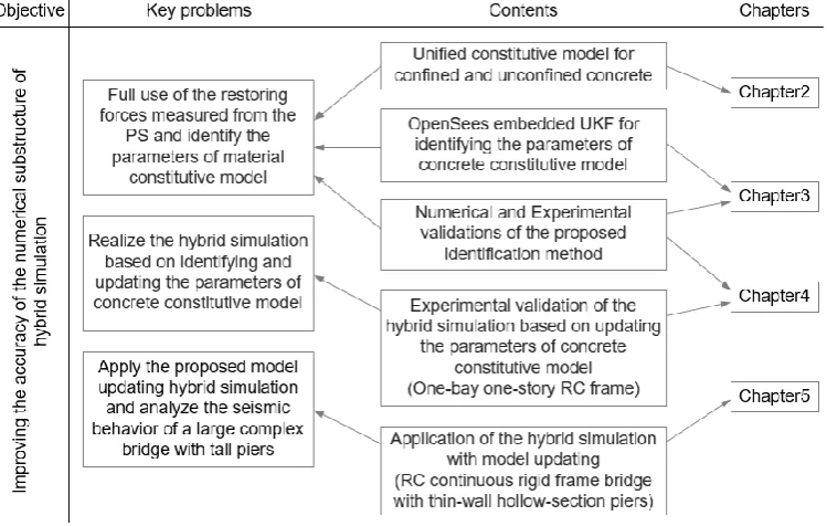
To solve the three key issues, four main parts of contents were finished as follow and the framework of the thesis and the arrangement of chapters are shown in Fig. 1-8.
Fig. 1-8 Research strategy
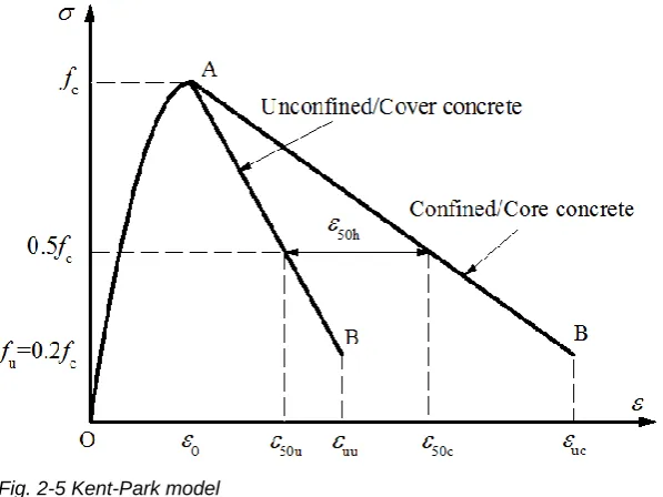
1. The conditions of model updating are given; the unified constitutive model of cover/unconfined and core/confined concrete which is suitable for model updating in hybrid simulation is derived based on the existing uniaxial concrete constitutive models; the approach for determining the initial values of the parameters in this unified model is given and the sensitivity analysis of these parameters were carried out to reduce the number of the parameters being identified.
scaled symmetry sampling method adopted in the unscented transform (UT) of UKF; verify the feasibility of concrete constitutive parameter identification by numerical method with concrete stress as measurement; propose the OpenSees embedded UKF to solve the identification problem when the restoring force is taken as the measurement; verify the proposed identification method through numerical simulation and analyze the reason for the fluctuations in the process of parameter convergence.
2
.
CONCRETE CONSTITUTIVE MODEL EMPLOYED FOR
PARAMETER IDENTIFICATION AND UPDATING
2.1 Introduction
For RC structures, the component constitutive models (CMs) which were mostly used in the model updating of hybrid simulation mainly focus on Bouc-Wen model. However, the Bouc-Wen model cannot include all the factors that influence the hysteretic behavior of component, such as the area of the cross-section, axial compression ratio, reinforcement ratio, etc. Take bridge structures as an example, if only one pier can is isolated to be the PS, the other piers with different sectional areas and stirrup ratios are numerically considered, and the Bouc-Wen model is adopted to represent the behavior of the experimental/physical substructure (PS) and as well as the numerical substructure (NS), then the parameters in the Bouc-Wen model of the PS are different with those of the NS. Hence, the parameters identified for the PS cannot be updated to the NS. That is, only when the factors that influence the hysteretic behavior of the PS are the same as those of the NS, the parameters can be updated. Therefore, it is limited to use the component CM for model updating in hybrid simulation.
The idea of identifying and updating the parameters of material CM is proposed for model updating hybrid simulation. In RC structures, the behavior of concrete and its simulation have more uncertainties than those of steel bars. So, the study is focused on the CM of concrete. Due to the complexity of concrete, a lot of efforts have been done on concrete CMs since the1960s. The concrete constitutive laws can be divided into one-dimensional (uniaxial), two-dimensional and three-dimensional models (Soliman & Yu, 1967; Li & Ren, 2007; Yu & Lu, 1998). Considering that the hybrid simulation may take a long time, the uniaxial concrete constitutive model was chosen as a case study. It can not only reduce the computational cost, but also provides sufficient precision for the nonlinear analysis of bending members such as the columns in frame structures and the piers in bridge structures. There are three kinds of axial constitutive models for concrete in OpenSees (now up to nine). The concrete01 model which has a good convergence is selected for simulating the mechanical behavior of concrete, whose parameters are identified and updated.
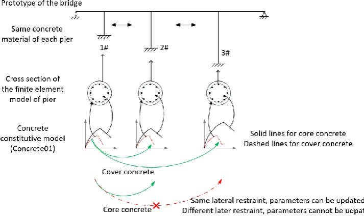
large structure can be considered as the PS. If the Concrete01 is employed to simulate the performance of the confined concrete, the parameters for the key components in the NS are different from those in the model of the PS. In this case, the identified parameters of confined concrete in the model of the PS cannot be directly used to update the NS.
To solve this problem, using the cover concrete as a bridge, a unified constitutive law of the core and cover concrete is derived to establish the relationship between the constitutive model of the core concrete in the NS and that in the numerical model of the PS. In this way, the parameter updating in hybrid simulation can be achieved.
2.2 Conditions for Model updating
Constitutive model (CM), also called constitutive law, is a mathematical model that reflects the macroscopic nature of matter. In civil engineering, a CM generally reflects the stress-strain relationship of a material. In order to establish a contrast relationship with the material CM, scholars have gradually put forward the concept of section CM and component CM. The section CM reflects the relationship of the restoring force (axial force and bending moment) and the curvature i