377
Mitigation of Harmonics and Ripples Analysis of Multipulse Converter
Manohar Vishwakarma1, Prashant Garg2Department of Electrical and Electronics Engineering Scope College of Engineering, Bhopal
1[email protected], 2[email protected]
Abstract: This paper deals with controlling the firing angle in multipulse converter through Phase Shift Zig-Zag Transformer. The Converter circuits investigated in this paper feed R-L loads. For high and ultra high voltage levels the soft switching multi pulse converters offers attractive merits because the component count suffices with the cost of the system. The mathematical model is accomplished by replicating the working behavior for converters with any number of rectifiers; 48-pulse and 60 pulse thyristor converters. The comparative study given in this paper covers cases of both the controlled multipulse converters by using Phase Shift Zig-Zag Transformer. As part of the simulated results on converters performance, data related to the Total Harmonic Distortion (THD), ripple in the output voltage, and power efficiency is provided.
Keywords: - Multipulse converter, Ripple, Harmonics distortion.
1.
IntroductionHarmonic distortion caused by nonlinear loads is appropriate a growing problem as nonlinear loads continue to become established in many commercial and industrial applications. Many techniques have been planned to solve the harmonic current problems. These solutions have mostly fallen into one of two categories: active current shaping and passive current shaping methods. Active current shaping methods deploy a Static Compensator (STATCOM) to supply load reactive power and harmonics. In general, a STATCOM uses the ordinary Current controlled Voltage Source Inverter (CC-VSI) circuit [1, 2] on the other hand, one of the main drawbacks to active current shaping techniques is an added complexity required for the STATCOM controller. Several control techniques for the STATCOM that are currently being used are p-q theory [3], direct and indirect current control techniques [1], [2], [4] notch filters [5], flux control [6], and dc-bus voltage control [7]. Multipulse converters are converters provided that more than six pulses of DC voltage per cycle from AC input or the converter having more steps in AC input current than that of six pulse bridge rectifier supply current. Phase shifting transformers are used to derive multipulse phase supply from three-phase AC mains using different combinations of transformer windings such as star, delta, zigzag, polygon, fork etc. In this thesis we use zigzag transformer.
The phase-shifting transformers play an input role in the multi-pulse rectifier's performance. Jiaopu et.al [1] discussed commonly used basic connections of
phase-shifting transformer, such as Scott, polygon, star/delta, extended-delta and zigzag and gave the analyses and comparisons between them. Focusing on 12-pulse phase-shifting transformers, the research highlighted possible strategies from basic connections to 12-pulse phase-shifting transformers which illustrate the evolution and its basic principles which may be extended to higher pulse converters.
The author Xigeng et.al [6] introduced the realization of phase-shifting of the multi-pulse converter transformer and the method for calculating stretch phase-shifting angle, triangle voltage and the 7 number of windings and analyzed the simulation for the 30-pluse rectification system based on this transformer. Arvindan et.al [7] proposed two 24-pulse rectifier topologies based on phase shifting using conventional magnetic over PSCAD environment.
1.1Harmonic Distortion
The currents of the line-commutated rectifiers are far from being sinusoidal. For example, the currents generated from the 3 phase full wave rectifier have the following harmonic content.
Some of the characteristics of the currents, obtained from Eq. (1) include: (i) the absence of triple harmonics; (ii) the presence of harmonics of order 6k ± 1 for integer values of k; (iii) those harmonics of orders 6k+1 are of
positive sequence; (iv) those of orders 6k − 1 are of
negative sequence; (v) the rms magnitude of the fundamental frequency is,
and the rms magnitude of the nth harmonic is
2.
Formulation of Pulse convertersThe 12-pulse rectifier was obtained with a 30◦ phase
shift between the two secondary transformers. The basis for increasing pulse configurations is provided by the parallel transformers. For instance, the operation of 24 pulses is achieved by means of four transformers with 15◦ phase shift, and 48-pulse operation requires eight
transformers with 7.5◦ phase shift. An ingenious and
378
load through a multistep reactor. The reactor uses a chain of thyristor-controlled taps, which are connected to symmetrical points of the reactor.
Fig 1: DC ripple reinjection technique of pulse operation
The thyristors located at the reactor is fired at the right time; high-pulse operation is reached. The pulse level operation depends on the number of thyristors connected to the reactor. The basic level of operation is multiplied to the two converters.
(a)System model
(b) Positive group arrangement Fig 2: Forty Eight-pulse converter
3.
Simulation Model of Pulse ConvertersThe present ac–dc converters are cost-effective for universal line and commercial voltage applications but are unreliable and fault prone for higher power
applications. Thus, to lighten these problems, multi stage and multi pulse converters have been developed with the flexibility to compliment with custom power switching modes. For high and ultra high voltage levels the soft switching multi pulse converters offers attractive merits because the component count suffices with the cost of the system.
3.1 Forty Eight-Pulse Converter
The simulation model for forty eight pulse thyristorized converter circuit is shown in Figure 2. The converter requires 8 star-zigzag transformers at input side, 4 in positive phase group and 4 in negative phase group along with four universal bridges in each group.
3.2 Sixty-Pulse Converter
The simulation model for sixty pulse thyristorized converter circuit is shown in Fig 3. In each group the converter requires 10 star-zigzag transformers at input side, 5 in positive phase group and 5 in negative phase group along with five universal bridges.
(a)System model
(b) Positive group arrangement Fig 3 Sixty-pulse converter
3.3 Measurement system
de-379
multiplexed for ripple, form factor and direct measurement and the measured signals are derived by a multi-meter.
4.
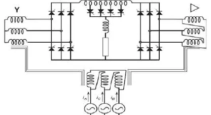
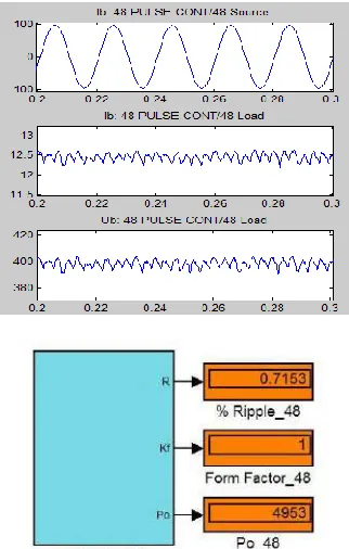
Results and Discussion Forty Eight Pulse ConverterThe forty eight pulse converter model based upon simulation for an output power of 5000 watts provided source current, load current and voltages as shown in below Fig 4(a). The Fig given in 4(b) is the evident from the results shown the output current and voltage waveforms are have considerable form factors magnitudes and the ripple are measured.
Fig 4: (a) Forty Eight pulse load voltage, source, and load current waveforms (b) For Forty Eight pulse converter
Form factor & Ripple.
Fig 5 (a) Output voltage v/s firing angle
4.1 Forty Eight Pulse Converter for Sweeping Firing Angle
The modeled forty eight pulse converter was simulated by sweeping firing angle in a range of 0 to 90 degrees, Fig 5 (a) shows firing angle and voltage output is a function
of %ripple and Fig.5 (b) shows load voltage, source and load current waveforms. The harmonic analysis of source current provided the THD as provided in Fig 7.
Fig 5 (b) % ripple v/s firing angle plot
Fig 6: Forty Eight pulse converter IS, IL & VL waveforms
for sweeping firing angle
Fig 7: Forty Eight pulse source current harmonic analysis.
4.2 Sixty Pulse Converter
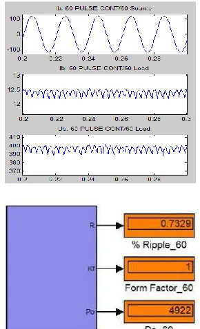
The sixty pulse converter model based upon simulation for an output power of 5000 watts provided source current, load current and voltages as shown in Fig 8(a). As is evident from the results shown the output current and voltage waveforms have considerable ripples, the ripple and form factors measured are illustrated in figure 8(b).
4.3 Sixty Pulse Converter for Sweeping Firing Angle
380
analysis of source current provided the THD as provided in Fig.11.
Fig 8: (a) Sixty pulse source, load current and load voltage waveforms (b)Ripple & Form factor for Sixty
pulse converter.
Fig 9(a) Output voltage v/s firing angle (b) % ripple v/s firing angle plot
4.4 Discussion over Simulation Results
The models for various converter prepared were simulated by using both continuous time and discrete time sampling mode and the solver used was ode23tb. The simulation results as illustrated in Table.1 the multi-pulse controlled converters provided low ripple contents and high form factors, the simulations were stable and were performed at constant load of 500 watts.
Fig 10: Sixty pulse converter IS, IL & VL waveforms for
sweeping firing angle
Fig 11: Sixty pulse source current harmonic analysis.
The converter firing angles were varied in step of 15 degrees and the converter output were closely observed and it was concluded that the window of control angles for these converters was 0 ≤α < 60 degrees, i.e. at 60
degree and onwards the voltage output of the converter experiences collapse and the ripple content randomly appears. Also the voltage control window increases with the increase in number of converter pulses, this is due to the smaller deviation between the angular phase outputs of phase shifting transformers. Most importantly the power quality profile improves with the introduction of additional pulses in the output as is evident from the harmonic analysis which in general suggest a decrease in T.H.D values.
Table.1: Multi-pulse converter comparison
5.
CONCLUSION381 REFERENCES
[1]. B. N. Singh, A. Chandra and K. Al-Haddad, "A DSP based indirect current controlled STATCOM-Part I: Evaluation of current control techniques", IEE Proceedings Electric Power Applications, vol.147, no.2, pp.107-112, March 2000.
[2]. B. N. Singh, A. Chandra and K. Al-Haddad, "A DSP based indirect current controlled STATCOM-Part II: Multi-functional capabilities", IEE Proceedings Electric Power Applications, vol.147, no.2, pp.113-118, March 2000.
[3]. P.K Singh, Y.K Chauhan, “Performance analysis of multi-pulse electronic load controllers for self-excited induction generator”, International Conference on Energy Efficient Technologies for Sustainability (ICEETS), pp-1299-1307, 2013. [4]. A Chaturvedi, D Masand, Gupta, S.; Tiwari, S.; Jain, M.,
“Comparative analysis of three phase AC-DC controlled multi pulse converter”, IEEE Students' Conference on Electrical, Electronics and Computer Science (SCEECS), pp 1-4, 2012.
[5]. Valderra; bano, A; Ramirez, J.M.; Correa, R.E., “A new 84-pulse VSC configuration using multi-level DC voltage reinjection for especial applications”, IEEE International Conference on Industrial Technology (ICIT), pp.1715-1720, 2010.
[6]. Xigeng Ma; Chao Li; Lina Bai; Ying Liu, “Analysis and Matlab Simulation of 30-Pulse Rectification System Based on Stretch Triangle Transformer”, International Conference on Electrical and Control Engineering (ICECE), pp 3312-3315, 2010.
[7]. A N Arvindan, A. Guha, “Novel topologies of 24-pulse rectifier with conventional transformers for phase