Vol.7 (2017) No. 6
ISSN: 2088-5334
Design and Implementation of Power Plant High-Side Voltage
Controller for Coordinated Voltage Control
Muhamad Tarmizi Azmi
#, Sheikh Kamar Sheikh Abdullah
#, Mohd Khairun Nizam Mohd Sarmin
#,
Nira Saadun
#, Nik Sofizan Nik Yusuf
*#
Department of Power System, TNB Research Sdn. Bhd., Bangi, Selangor Darul Ehsan, Malaysia.
E-mail: [email protected], [email protected], [email protected], [email protected]
*
Department of Transmission, Tenaga Nasional Berhad, Bangunan Dua Sentral, Kuala Lumpur, Malaysia. E-mail: [email protected]
Abstract— This paper describes the design and implementation of the Power Plant Voltage Controller (PPVC) with an adaptive
control which equips at the power plant level with the local high side voltage control. The Power Plant Voltage Controller is part of the hierarchical voltage control system which consists of Tertiary Voltage Control (TVC) at the higher control level and then followed by Secondary Voltage Control (SVC) as a regional controller and Primary Voltage Control (PVC) at the lowest control level to
perform the control command. In this control approach, PPVC participates in the lowest control level in the Coordinated Voltage
Control (CVC) system. The Power Plant Voltage Control regulators are autonomous controllers that regulate the high-side bus of the power plant while maintaining balanced VAR generation of the individual units and avoiding the dynamic interaction among multiple controlled generators. This paper presents a method of controlling the terminal voltage of the generators at the power plant by utilizing a quasi-steady-state sensitivity to get a control parameter for the PPVC. Using a simple control strategy, an adaptive control can be achieved by periodically calculating the quasi-steady-state sensitivity to update the control parameter, in such a way the PPVC control parameter not only can adapt to the variation of the interconnected network but also with the fluctuation of the load demands.
Keywords— coordinated voltage control; quasi-steady-state sensitivity; high-side voltage control; power plant voltage regulator
I. INTRODUCTION
In a modern power system, many power utilities and system operators facing a challenging task to control the transmission voltage to improve the security and efficiency of power system operation. The need for suitable control solutions that capable of controlling the grid voltage and reactive powers has become more critical in recent years. The lack of real-time and closed-loop coordination of reactive power resources appears in common network voltage control practice; In current practice, system voltage control largely carried out manually by the system operator worldwide, which typically involves scheduling the power plants high-side voltages, switching the banks of shunt capacitors or reactors, and adjusting the tap changer of the transformer.
Moreover, with the scale and operational complexity of the power grid are increasing, it becomes impractical for system operators to manually coordinate a large number of widely distributed voltage/VAR control devices in real-time. In order to improve voltage control in transmission grids,
In China, Tsinghua University has developed a commercial Automatic Voltage Control (AVC) system and this AVC system has been implemented in many control centers in China and also it has been tested on the PJM system [9]. TNB Research (TNBR) through collaborative work with Tsinghua University has conducted a comprehensive simulation study of automatic Coordinated Voltage Control (CVC) for TNB system [10] and CVC system currently under development at TNB Research.
In this paper, we present a new technique for the power plant high-side voltage controller, which suitable to be used in a multilevel automatic control system like in Coordinated Voltage Control (CVC) application. This technique utilizes the quasi-steady-state sensitivity to get a control parameter for the power plant high-side voltage controller. Through a simple control strategy, an adaptive control can be implemented using the online computation of the quasi-steady-state sensitivity to update the controller parameter.
A. Principle of the Coordinated Voltage Control
Fig. 1 Control architecture of the hierarchical CVC system
The idea for controlling hundreds of transmission bus voltage in an automatic manner is very complex, not reliable and not economical. The simple voltage control system should consider the dominant buses only, thus allowing a sub-optimal but feasible and reliable control solution. The basic principle of Coordinated Voltage Control (CVC) system is to divide the transmission network into several decouple zones which are simpler to control, and each of the control zones will have its own pilot nodes which selected from the dominant buses (in a small amount). Pilot buses are selected to represent the overall voltage profile in a control zone. This implies that voltage variations at the pilot nodes may represent the voltage evolution throughout the zone. The CVC system, control pilot nodes voltage through a hierarchical control structure which made of three control levels.
The first hierarchical level referred as Primary Voltage Control (PVC). PVC essentially refers to the voltage controller of generators, synchronous condensers, static var compensators and another voltage controller in the network. These controllers receive the voltage set-point from the outputs of the higher control level. PVC responsible for maintaining the voltage at the set-point values against rapid voltage variation over a short interval and its time constant is in the order of a fraction of a second.
The second hierarchical level referred as Secondary Voltage Control (SVC). The main objective of SVC is to control the pilot bus voltages by keeping the pilot bus voltages at the set-point values through dynamically adjust the control variable in PVC level, such as the set-point values (generators, static var compensators and etc.) or discrete control signals (reactors, capacitors, and tap changers) in a given control zone at the slower speed. In essence, SVC receives the voltage set-point of the pilot buses from the outputs of the higher control level and implements the coordinated control of PVC equipment inside the voltage control zone, and it has a time constant of a few minutes.
On the third hierarchical level, a Tertiary Voltage Control (TVC) which is the highest level in the hierarchical control architecture is designed to achieve safe and economical system operation through minimizing power transfer losses while considering security constraints. TVC acts as a wide area optimization controller, which uses an optimal power flow technique to provide an optimal reference value for the pilot bus voltage for each control zone with the selected time constant might vary from 15 min to several hours depending on the situation.
The CVC system basically composed of two physical parts, the first part is centralized control system which was known as a Control Center Master Station (CCMS) and the second part is decentralized control devices which also known as a Power Plant Voltage Controller (PPVC). The PPVCs device is installed in the power plants to track the control commands from the control center, while the CCMS basically installed at the control center to coordinate the control actions of all decentralized PPVCs. A principle scheme that represents the architecture of a hierarchical CVC system is shown in Fig. 1.
B. Power Plant Voltage Controller in Coordinated Voltage
Control
In order to regulate the pilot nodes voltage according to their set-point values, SVC will determine the control strategies to achieve that target, according to reactive sources available in their control zone which include the reactive power of the generators. Therefore, a new power plant apparatus is required to control this reactive power production of the generating units by taking into account the actual operating constraints, such as reactive power limit, stator voltage limit, excitation system failure, communication failure and etc. Due to this concern, TNB Research (TNBR) has developed new equipment to fulfill such requirement. This device is known as Power Plant Voltage Controller (PPVC).
reactive level received from the higher control level, while the second mode, it regulates the local high-side bus-bar voltage on the basis of a suitable daily voltage trend or an operator-defined set-point [5], [6]. The detailed function of the REPORT also can be found in [11], [12].
Review of the literature revealed that, there are a number of control practices that able to coordinate the reactive powers of the operating generators in the power plant such as Power System Voltage Regulator (PSVR) which develop by Tokyo Electric Power (TEPCO) and also Advanced High Side Voltage Control (HSVC) regulator, develop by the Mitsubishi Electric Corporation (MELCO). Essentially, this controller utilizes the concept of a line drop compensation to support the power plant high-side bus-bar voltage. This practice increases grid voltage support, but might introduces destabilizing interactions between primary voltage regulators. In addition, the setting for droop value which remains constant during the operational process can lead to degradation of the dynamic performance and reduce the stability margins of the power plant high-side bus regulator during the variation of the system network and also fluctuation of the load demands.
In order to deal with this issue, the appropriate solution to handle the dynamic system with parameter variation like power system is through automatic adjustment of the control parameter for power plant controller during the online operation. In literature, this control method, also known as linear parameter varying (LPV) controller, which transform the nonlinear system into a linear parameter-varying system [13]. An adaptive control strategy has been adopted in the REPORT controller in the Italian power system, based on the real-time identification of the external equivalent reactance; hence the REPORT control parameters can be updated with the purpose to adapt with the different dynamics of the system [11]. Using a similar control strategy, an adaptive control can be achieved by periodically calculating the quasi-steady-state sensitivity to update the control parameter of the Power Plant Voltage Controller (PPVC).
II. MATERIAL AND METHOD
One of the crucial design aspects in the development of the Coordinated Voltage Control (CVC) system is the dynamic design of the overall system under CVC operation, which requires a defined design of their stability and dynamics. In the CVC system, the control architecture is based on the concept of hierarchical control, which consists of overlapped closed-loop controls from the higher control level (TVC) to the lower control level (PVC). In order to achieve adequate dynamic performance, the control solution is through substantial dynamic decoupling between overlapped levels, which lead to the criterion that requires the time-decomposition dominant time constant of any external control loop be higher than the dominant time constants of all its internal loops. In other words, an external voltage control loop must be slower than the internal voltage control loop. Such a criterion also applies to all voltage control levels in CVC system, which resulting the PPVC control loop to be much slower than a generator AVR control loop, while SVC control loop much slower compared
with PPVC and generator AVR control loop and this also applies for a TVC control loop.
In PPVC, the local high-side bus bar voltage regulation is designed with the control law of proportional-integral (PI) type, and in order to guarantee a relevant time decoupling between the AVRs and the externally overlapped PPVC control loops, the PPVC control loop is designed to be at least hundreds times slower than the AVR dynamics. Due to this design requirement, the dominated time constant for PPVC must be hundreds of times greater than AVR time constant.
A. Conceptual Design of Power Plant Voltage Controller
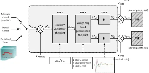
Fig. 2 shows the conceptual design of the Power Plant Voltage Controller (PPVC). To increase the reliability of the PPVC, the controller is designed to obtain the set-point value from three input selection which used to handle a different kind of issue that might happen during the operation. In normal condition (remote control mode), PPVC obtain the set-point value from the Secondary Voltage Control (SVC) and in the case of loss communication between the control center and the plant, PPVCs are still able to operate in local mode control by obtaining the manual set-point value given by operators or tracking the pre-defined set-point curves which already configured by operators as a backup. In order to understand the working principle of the PPVC, the control step is divided into three main steps.
Fig. 2 Conceptual design block of power plant voltage controller
B. Functional Scheme of Power Plant Voltage Controller
Fig. 3 shows the functional scheme of the Power Plant Voltage Controller (PPVC). Basically, this functional scheme consists of the following modules.
• Human Machine Interface (HMI): As an interface between the operators and PPVC device at the power plant which graphically presents the current state of PPVC such as on-off status or blocking signals from the AVRs, and also displays the actual measurements of voltage and power from the fields. It does also allow operators to set a reference target for PPVC or change PPVC control mode.
• Control system block: This module executes the real-time code to implement the entire PPVC control algorithm based on the three control steps, which has been discussed in the previous section. The illustration inside this block is shown in Fig. 4.
• Finite State Machine (FSM): This module realizes all the logic functions to be handled such as start/stop sequences and protection function which automatically block the PPVC operation under abnormal network condition. It also performs the control status for each of the control generators based on the operational constraint (i.e.: generator stator voltage limit, generator reactive power limit, excitation system failure and communication failure)
• Communication protocol: Control the I/O activities, which include remote communication between PPVC unit and control center master station (CCMS) and also local communication between PPVC unit and DCS (Distributed Control System) of the power plant.
Fig. 3 Functional scheme of power plant voltage controller
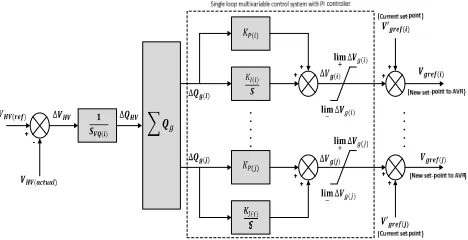
Fig. 4 Control system block diagram of power plant voltage controller
C. The Design of Control System for Power Plant Voltage
Controller
The power plant which is part of components in power system can be classed as multivariable systems; the interactions among various input and output variables of a system make design technologies in multivariable control systems fundamentally different from single-variable control systems. In many multivariable systems, single-loop controller design is often implemented by controlling individual feedback loop, where decoupling is employed to decouple the interaction between input and outputs variables. This method has been successfully applied in many control engineering applications related to multivariable control problems.
In the context of the power plant high-side bus voltage control application, the controller must have the ability to regulate the high-side bus of the power plant by controlling multiple set-points of generator AVRs simultaneously while avoiding the dynamic interaction among multiple controlled generators. Basically, PPVC utilizes the similar approach that widely used to solve the multivariable control problem. In this application, each of the generators is controlled individually by introducing an external proportional-integral (PI) controller, which overlapped with the internal controls of generator AVR (refer Fig. 4) and the decoupling strategy is achieved based on the proper selection of the control parameter for PPVC controller.
Fig. 4 shows the control system models of PPVC which developed based on the conceptual design that we have already discussed in the previous section. The dynamic design of the external control system consists of choosing the time constants of the integrators and a proper design of and coefficients of the PI control law. The PPVC control loops are introduced by assuming that they are slower with respect to generator AVR voltage control loop. The typical value of the AVR time constant, is in the range of 0.5 to 1s; in order to guarantee a relevant time decoupling between the AVRs and the externally overlapped PPVC control loops, the PPVC control loop is designed to be hundreds times slower than the AVR dynamics which determines the high-side voltage control loops dynamic with the dominant time constant of 50 s or higher. Through this way, the faster control loop will not be affected by the slower control loop since the latter will appear to be more stationary during the interval that the former is completing its latest setpoint change and the faster control loop will have finished its work by the time the slower control loop gets underway.
Consider the PI feedback control system, the mathematical equation of the controller in the time domain and the corresponding transfer function of the controller can be expressed in (1) and (2).
( ) = ( )− + !# ( )− " (1)
$(%) = & +'(
) (2)
online at the Control Center Master Station (CCMS). The quasi-steady-state sensitivity analysis is calculated based on the Jacobian matrix of the Newton-Raphson method which provides information the effect of the controlled parameter on the system response based on the current operating condition of the power system network. The design procedure to determine the controller gain based on the result of the sensitivity analysis is started by getting the sensitivity matrix of ** Δ,⁄Δ , , which represent the relation between the variation of generator terminal voltages with respect to the variation of reactive power at the generator bus. The proportional coefficient and integral coefficient is computed according to the following equation,
= -./01
.22034 ,,((() (3)
= 567
./018 =
-9::((()
.22034 (4) Where ,,((() indicates the diagonal element of sensitivity matrix **, of ;< generator. The details of the sensitivity analysis method will be discussed in the next section. For now, by looking at the proportional coefficient and integral coefficient , it is clear that the value of sensitivity plays an important role to make sure that the performance and stability of the controller are guaranteed over the entire operating condition since other parameters are set to remain constants. It is important to highlight that dynamic system behavior like power system is highly nonlinear, therefore adopting linear controller in a nonlinear system with constant gains can cause degradation on the stability and also the performance of the system since the controller with fixed gain is designed to operate at only a specific range of operating conditions. To cope with this problem, the Power Plant Voltage Controller (PPVC) must equip with an adaptive controller.
D. Sensitivity Analysis and Techniques for Adaptive Control
In this section, we introduced a simple adaptive control technique for power plant voltage controller, which utilizes the quasi-steady-state sensitivity to determine the PPVC controller gain. The formulations of the quasi-steady-state sensitivity are given in details in this section. In general, application of the quasi-steady-state sensitivity forms a vital part in the CVC system, since it acts as a primary input to an almost entire main component in CVC system such as in adaptive zone division, pilot bus selection, secondary voltage control, substation voltage control and also in the power plant voltage control. Hence, the accuracy and efficiency of the sensitivity module are the primary concern since it makes a significant impact on the whole CVC system.
Sensitivity analysis is a classical analytical method for power system network, which based on the linearization of the power flow equation. However, the conventional sensitivity cannot simulate the physical response of an actual power system realistically. Hence, a new method called quasi-steady-state sensitivity analysis method is suggested to address this problem. This method has been discussed in great details in [14]. In this paper, we simply concentrate on the formulation of sensitivity analysis for voltage control application.
According to the power flow algorithm of Newton-Raphson method, the power flow equation can be expanded into Taylor series and the Jacobian matrix holding the first-order partial derivatives of the power flow equations with respect to all the algebraic variables can be written as
=∆>∆ ? = =@@ AA @@ ? B∆C∆ D (5)
by taking into account the decoupling between the active and reactive powers, the values of the elements in the submatrix
@ and @ A are very small. Hence, the Jacobian matrix can rewrite as
=∆>∆ ? = =@0 @ ? BA 0 ∆C∆ D (6)
and by separating the equations describing the dependence in the power system between reactive powers and the voltages, the equation can be depicted as
F∆ G = H@ IF∆ G (7)
From (7), a submatrix of @ can be further rearranged based on the physical response of the bus. Under quasi-steady-state, generator bus, which equips with an automatic voltage regulator (AVR) is considered as PV-bus, but generator bus with automatic reactive power regulator (AQR) or automatic power factor regulator (APFR) is considered as PQ-bus. All the load buses are considered as PQ-bus. Therefore, separating the bus between the “g” called PV-bus from “d” called PQ-bus, it’s possible to write
=∆∆ ,
J? = =
K,, K,J
KJ, KJJ? =∆
,
∆ J? (8)
The calculation formulas of quasi-steady-state sensitivity for reactive power can be derived from (8), and the equation can be rearranged as
∆ J= KLMJJ∆ J+ KLMJJKJ,∆, (9)
∆ ,= K,,− K,JKLMJJKJ, ∆,+ K,JKLMJJ∆ J (10)
Supposed when ∆ J is regulated and , is kept unchanged,
∆,= 0, we can calculate sensitivity matrices of N N and : N using (11) and (12) respectively. Similarly, supposed when ∆, is regulated and J is kept unchanged, ∆ J= 0. We can compute sensitivity matrices of N : and : : using (13) and (14) respectively.
N N =
∆ N
∆ N= KJJ
LM (11)
: N =
∆ :
∆ N= K,JKJJ
LM (12)
N :=
∆ N
∆ := −KJJ
LMK
J, (13)
: :=
∆ :
∆: = K,,− K,JKJJ
LMK
In essence, only (11) and (14) is used for PPVC application, other types of sensitivity matrices are used for different application in CVC system. The diagonal elements of the matrix (11), OP OP is used to transfer the bias of the high-side bus voltage ∆ into the total reactive power demands ∆ . The second function of the sensitivity in PPVC is used to update PI controller parameter. As mentioned in the previous section, the PI controller gain for PPVC is determined based on the sensitivity matrix of ** Δ ,⁄Δ , ; therefore, in order to get this sensitivity matrix, it requires the inversion of : : ∆ ,⁄∆, sensitivity matrix. However, by directly inverting this sensitivity matrix, it may not actually represent the actual physical response of the electrical component in the power system. In a quasi-steady-state sensitivity analysis, the physical responses of electric power equipment are taken into account, when the primary control (or disturbance) is executed, the system state shift from the original state to a new steady state and the transient process between these two states are ignored.
Consider the response of the generator terminal voltage which equipped with AVR, supposed when the reference voltage of one generator is regulated, after the system reaches a new steady state, we notice that only the voltage of the regulated generator will change while other generator voltages are maintained cause by physical response of the AVR. Therefore, coefficient matrix expressing the quasi-steady-state physical response of the control variable to system disturbance or control is introduced; this coefficient matrix needs to be multiplied by the sensitivity matrix of
: : ∆ ,⁄∆, using the Schur multiplication method before performing the inversion algorithm. The equation can be depicted as
**= K,,∘ R LM (15)
Where the coefficient matrix expressing the physical response of the control variable is represented by the identity matrix,R. The diagonal element of sensitivity matrix **, provide information on the relationship between the variations of generator terminal voltages with respect to the variation of reactive power at the generator bus.
A controller with parameter adaptation is introduced in the Power Plant Voltage Controller (PPVC) since the controller would be affected by the power system nonlinearities such as variable operating conditions of the power plant, variation of load demand and the variation of the network impedance seen from the power plant caused by frequent transmission line switching or rapid development of new transmission line. One of control technique used when a controlled plant is highly nonlinear is a linear parameter varying (LPV) technique. In linear parameter varying technique, the nonlinear system is transformed to a linear parameter-varying system, which treated the nonlinear system as linear systems with varying parameters and thus allowing linear control techniques to be applied for nonlinear systems. The variation of each of the parameters is not known in advance but is assumed to be measurable in real-time. Based on the concept of the LPV technique, the power system can be depicted as linear time-varying plants where the Jacobian matrix which represents the linear state space
system can be computed based on the online measurements. This Jacobian matrix is calculated from the solved power flow algorithm of the Newton-Raphson method, and then it is applied to compute the quasi-steady-state sensitivity which used to determine the controller parameter.
In other words, if the sensitivity function can be generated online with the purpose to adapt to the variation of the system condition, then the adaptive law is implementable. From a practical point of view, online monitoring of power system can be done with the help of state estimator (SE) program in Energy Management System (EMS). SE periodically computes an estimate of the operating state of the network of interest thereby producing an approximate model of the true operating state of the system. Therefore, in this paper, we introduced a new method to achieve the adaptive control strategy based on the online computation of the controller parameter using quasi-steady-state sensitivity.
E. Development of Power Plant Voltage Controller Using
Real-Time Application Platform (RTAP)
Due to lack of the control devices in the market which suitable to perform high-side bus voltage control for Coordinated Voltage Control application, most of the involved utilities need to develop these devices by themselves. In TNB Research, we specifically design, develop and tested the PPVC device in the power system laboratory using a real-time digital simulator (OPAL-RT). Essentially, the PPVC is developed as an application module inside the Real-Time Application Platform (RTAP).
Since 2010, the power system laboratory in TNB research has developed highly advanced equipment in term of the number of functions it offers to support wide-area intelligent system application. RTAPs is a powerful processing platform that capable of handling multiple data acquisition sources with a different communication protocol, performing local data processing and executing control commands to multiple controllers and it acts as a generic platform for real-time wide area measurement, monitoring, control and protection applications. In general, RTAP offers the following features:
• Multiple type of communication protocol such as, it support interface to control center SCADA system using IEC101, IEC104 or MODBUS protocol and it also support the Inter-Control Center Communications Protocol (ICCP), on the other hand it also adopt the latest communication standard like IEC61850 server-client, Generic Object Oriented Substation Events (GOOSE) message as publisher and subscriber and it also has a Phasor Data Concentrator (PDC) functionality to collect data from different PMU using IEEE C37.118 standard.
• Logic operation and mathematical module to execute and perform user-defined programmable logic and standard mathematical operation from the real-time input data collection.
• Equipped with control block with standard controller modules for PI or PID controller.
• Web services to provide the ability for the user to monitor the real-time information relevant to the RTAP through the web using any modern browser on any operating system.
Generally, RTAPs run on the PC-based real-time embedded operating system, and it can be extended for the cooperative process, or it can be a complete automation system which capable to communicate with another environment such as power plant DCS (Distributed Control System). Therefore, by utilizing the capability and flexibility of RTAP features, it enables TNBR to develop new power plant apparatus with the capabilities to control the reactive power production of the multiple generating units by taking into account the actual operating constraints, like reactive power limit, stator voltage limit, excitation system failure, communication failure and etc. Fig. 3 shows the functional scheme of the PPVCs inside the RTAP which consist of control system block, finite state machine, and communication protocol.
III.RESULTS AND DISCUSSION
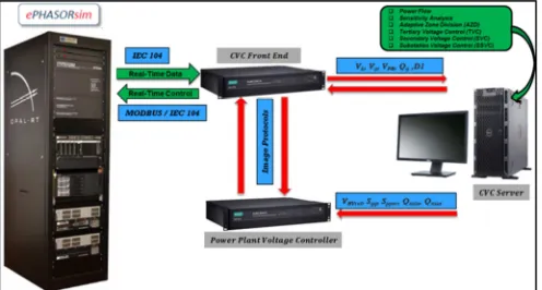
In order to verify the performance of the power plant voltage controller, unit testing on the actual PPVC device is conducted in the TNBR power system laboratory through a hardware-in-the-loop (HIL) simulation using the OPAL-RT real-time digital simulator. In this simulation, the whole TNB power grid is simulated in the phasor domain simulation, and the physical PPVC device is interfaced with the selected TNB power plant which modelled in the simulator using communication protocol IEC104 and MODBUS. The dynamic response of the PPVC is studied under three different kind of network perturbations; step variation of the load demands (reactive power), step variation of high-side bus voltage setpoint and also the transient response of the PPVC under three-phase fault at the high side bus of the power plant. Fig. 5 shows the deployment diagram of the HIL test setup which conducted in TNBR power system laboratory.
Fig. 5 Deployment diagram of the HIL test setup for CVC system
Fig. 6 shows the dynamic response of high side bus voltage, without and with PPVC device under a sudden reactive power load change occurs at the high-side bus. It can be seen that the high-side bus voltage can be maintained even after the load disturbance occurred; the PPVC automatically send the new set point to the generators AVR to adapt this perturbation. Meanwhile, without the PPVC is
operated, there is no mechanism to update generators AVR set point to adapt to this new change. Therefore, generators AVR only maintained its previous setpoint value, causing the high side voltage to drop to a new steady state value.
Fig. 6 Dynamic response of under step variation of the load
In order to prove that there is no appreciable interference between PPVC controller and existing power plant controller, a three-phase fault is applied at the high side bus of the power plant. Fig. 7 shows that there is no significant difference on the high side bus voltage during the transient phenomena due to the fact that the nature of the PPVC controller is really slow compared with the response of the other controller in the power plant.
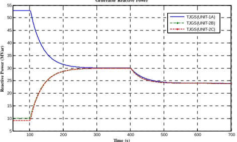
To demonstrate the behavior of PPVC under the regulation of different voltage setpoint, adjustment of ± 0.01 p.u from current-voltage setpoint is performed. The result shows a very stable response with PPVC controller successfully achieve its setpoint value within 250s. The dynamic response of the generator reactive power is also shown here to indicate the effectiveness of the balancing algorithm for generator reactive power in PPVC. Furthermore, there is no dynamic interaction among the multiple controlled generators occurred, which proves that the control parameter is good for PPVC using a quasi-steady-state sensitivity. The result of this experiment is shown in Fig. 8 to Fig. 10.
Fig. 7 Transient response of under three-phase fault at high side bus of the power plant
200 250 300 350 400 450 500 550 600
279.1 279.2 279.3 279.4 279.5 279.6 279.7 279.8 279.9 280
Time (s)
V
o
lt
a
g
e
(k
V
)
High Side Bus Voltage (TJGS275-PPVC1)
Set-point voltage Voltage without PPVC Voltage with PPVC
280 290 300 310 320 330 340 350
260 265 270 275 280 285 290 295 300
Time (s)
V
o
lt
a
g
e
(k
V
)
High Side Bus Voltage (TJGS275-PPVC1)
Fig. 8 Dynamic response of under step variation of voltage setpoint
Fig. 9 Dynamic response of generator voltage under step variation of voltage setpoint
Fig. 10 Dynamic response of generator reactive power under step variation of voltage setpoint
IV.CONCLUSIONS
The paper has presented a details description on the design and implementation of the power plant high side voltage controller for Coordinated Voltage Control system in TNB. The working principle of PPVC has been described in great details in the earlier section including the functional component in PPVC and its dynamic design. The mathematical formulation to compute the quasi-steady-state sensitivity analysis is also presented in this paper. The proposed method utilizing a quasi-steady-state sensitivity module (QSENS) which calculated online at CVC Control Center Master Station (CCMS) using online data from the State Estimator (SE) results in Energy Management System (EMS). Generally, an almost entire main component in CVC utilizing quasi-steady-state sensitivity in their control strategies which make it as the most essential module in
CVC system. Through a simple control strategy, an adaptive control can be achieved by using online quasi-steady-state sensitivity result to update the controller parameter. The result on the dynamic performance of the PPVC is very promising for practical applications; the PPVC able to maintained their dynamics design under different kind of network perturbations.
ACKNOWLEDGMENT
The authors gratefully acknowledge the contributions of TNBR project members, TNB Transmission and external service collaborator for their valuable inputs, comments, support and technical cooperation during the project studies and system development. These works are fully funded by Tenaga Nasional Berhad under TNB R&D Fund thru research projects R-T-RD-0073-12-021.
REFERENCES
[1] V. Arcidiacono: “Automatic Voltage and Reactive Power Control in Transmission Systems” in Proc. of 1983 CIGRE-IFAC Symposium Florence 1983, Survey paper E.
[2] J. P. Paul, J. Y. Leost, and J. M. Tesseron, “Survey of the secondary voltage control in France: Present realization and investigations”, IEEE Transaction on Power Systems., Vol. PWRS-2, No. 2, May 1987.
[3] P. Lagonotte, J. C. Sabonnadiere, J.Y. Leost, J.P. Paul, “Structural analysis of the electrical system: application to secondary voltage control in France,” IEEE Trans. Power Systems, vol.4, pp. 479-486, May 1989.
[4] J.P.PAUL, J.Y.LEOST “Improvements in secondary voltage control in France” , Power Systems & Power Plant Control: Proceedings of the IFAC Symposium, BEIJING, 1986.
[5] S. Corsi, M. Pozzi, C. Sabelli, A. Serrani: “The Coordinated Automatic Voltage Control of the Italian Transmission Grid- Part I: Reasons of the Choice and Overview of the Consolidated Hierarchical System” IEEE Trans. on Power Systems, vol. 3. NO. 4, November 2004, pp: 1723-1732.
[6] S. Corsi, M. Pozzi, M. Sforna , G. Dell'Olio: “The Coordinated Automatic Voltage Control of the Italian Transmission Grid- Part II: Control Apparatus and Field Performance of the Consolidated Hierarchical System” IEEE Trans. on Power Systems. Vol. 19. NO. 4, November 2004, pp: 1733-1741.
[7] H. Sun, Q. Guo, B. Zhang, W. Wu and J. Tong, “Development and Applications of System-wide Automatic Voltage Control System in China,” in Proc. 2009 IEEE Power & Energy Society General Meeting, pp. 1-5.
[8] H. Sun, Q. Guo, B. Zhang, W. Wu and B. Wang, “An Adaptive Zone-Division-Based Automatic Voltage Control System With Applications in China,” IEEE Trans. Power Systems, vol. 28, pp. 1816-1828, May 2013.
[9] Q. Guo, H. Sun, J. Tong, M. Zhang, B. Wang, B. Zhang, “Study of System-wide Automatic Voltage Control on PJM System,” in Proc. 2010 IEEE Power & Energy Society General Meeting, pp. 1-6. [10] M.K.N.M. Sarmin, S.K.S. Abdullah, M.T. Azmi, N. Saadun, F.H.
Ismail, M. Zhang, Q. Guo, H. Sun, “A Systematic Study of System-wide Automatic Coordinated Voltage Control for TNB System” 2014 IEEE Innovative Smart Grid Technologies - Asia (ISGT ASIA)
[11] S. Bittanti, S. Corsi, M. Pozzi, and M. Zaramella, “The power plant voltage/reactive power regulator with an adaptive control solution,” in Proc. Powertech Conf., Bologna, Italy, 2003.
[12] G. Sulligoi, M. Chiandone and V. Arcidiacono, “NewSART Automatic Voltage and Reactive Power Regulator for Secondary Voltage Regulation: Design and Application”, IEEE PES General Meeting, Detroit, July 2011.
[13] J. Mohammadpour, K. Grigoriadis, M. Franchek, and Y.Y. Wang, “LPV Decoupling for Multivariable Control System Design,” in Proc. American Control Conference, St. Louis, MO, Jun. 2009. [14] H.B. Sun, B.M. Zhang, “A systematic analytical method for
quasi-steady-state sensitivity,” Electric Power Systems Research 63 (2002) 141-147.
100 200 300 400 500 600 700
279 279.5 280 280.5 281 281.5 282 282.5 283 X: 393 Y: 282.5 Time (s) V o lt a g e (k V )
High Side Bus Voltage (TJGS275-PPVC1)
X: 654 Y: 279.8 Set-point voltage TJGS275 voltage
S ettling Time 250
Reach set-point voltage
100 200 300 400 500 600 700
15.25 15.3 15.35 15.4 15.45 15.5 15.55 Time (s) V o lt a g e (k V )
Generator Terminal Voltage
TJGS(UNIT-1A) TJGS(UNIT-2B) TJGS(UNIT-2C)
100 200 300 400 500 600 700
5 10 15 20 25 30 35 40 45 50 55 Time (s) R ea ct iv e P o w er ( M V a r)
Generator Reactive Power