www.fm.viamedica.pl
Address for correspondence: Dr. S. Tunali, Department of Anatomy, Hacettepe University, Faculty of Medicine, 06100, Ankara, Turkey, tel: +90 312 3052107, fax: +90 312 3107169, e-mail: [email protected], [email protected]
Computerised 3-D anatomical modelling
using plastinates: an example utilising
the human heart
S. Tunali
1, 2, K. Kawamoto
1, M.L. Farrell
1, S. Labrash
1, K. Tamura
1, S. Lozanoff
11Department of Anatomy, Biochemistry, and Physiology, John A. Burns School of Medicine,
University of Hawaii, Honolulu, HI, USA
2Department of Anatomy, Hacettepe University Faculty of Medicine, Ankara, Turkey [Received 29 April 2011; Accepted 8 June 2011]
Computerised modelling methods have become highly useful for generating elec-tronic representations of anatomical structures. These methods rely on cross-sectional tissue slices in databases such as the Visible Human Male and Female, the Visible Korean Human, and the Visible Chinese Human. However, these da-tabases are time consuming to generate and require labour-intensive manual digitisation while the number of specimens is very limited. Plastinated anatomi-cal material could provide a possible alternative to data collection, requiring less time to prepare and enabling the use of virtually any anatomical or pathological structure routinely obtained in a gross anatomy laboratory. The purpose of this study was to establish an approach utilising plastinated anatomical material, specifically human hearts, for the purpose computerised 3-D modelling. Human hearts were collected following gross anatomical dissection and subjected to routine plastination procedures including dehydration (–25oC), defatting, forced
impregnation, and curing at room temperature. A graphics pipeline was estab-lished comprising data collection with a hand-held scanner, 3-D modelling, model polishing, file conversion, and final rendering. Representative models were viewed and qualitatively assessed for accuracy and detail. The results showed that the heart model provided detailed surface information necessary for gross anatomi-cal instructional purposes. Rendering tools facilitated optional model manipula-tion for further structural clarificamanipula-tion if selected by the user. The use of plastinat-ed material for generating 3-D computerisplastinat-ed models has distinct advantages compared to cross-sectional tissue images. (Folia Morphol 2011; 70, 3: 191–196)
Key words: plastination, heart, hand-held scanner, 3-D modelling
INTRODUCTION
Computerised modelling methods have become highly useful for generating electronic representa-tions of anatomical structures. These methods rely on cross-sectional tissue slices in databases such as the Visible Human Male and Female, the Visible Ko-rean Human, and the Visible Chinese Human [18,
19, 21, 23]. However, these databases are time con-suming to generate and require labour-intensive manual digitisation while the number of specimens is very limited.
(3-D) computerised models. Qiu et al. [15] demonstrat-ed that computerisdemonstrat-ed 3-D models of the human tem-poral bone and internal structures could be gener-ated following plastination and sectioning at 1 mm intervals with subsequent volumetric reconstruction and surface rendering. Subsequently, Doll et al. [4] reported successful computer modelling of the hu-man kidney utilising E12 plastination method fol-lowed by macrotome sectioning and surface recon-struction. In a similar fashion, sheet plastination methods were used to generate a cross section of a human brain that provided a base image for ani-mating traumatic brain injury resulting in either epi-dural or subepi-dural hematomas [8]. Sora et al. [17] extended this approach by utilising sheet plastina-tion to generate a series of transverse secplastina-tions of the human ankle that were digitised, relevant tis-sue borders were extracted, and contours were sub-jected to 3-D computerised surface modelling. Al-though these authors demonstrated that plastinat-ed anatomical material could be usplastinat-ed for 3-D mode-lling in a manner similar to that facilitated by the various visible human databases, database genera-tion comprising cross-secgenera-tional anatomical material can require painstaking and laborious methodolo-gy including large tissue macrotome sectioning and digitisation. These steps can require user interven-tion on the order of years [12]. Thus, a method that avoids tissue sectioning could provide a more time effective alternative.
Recently a multiple exchange format approach has been reported that includes a graphic pipeline characterised by a series of steps aimed at generat-ing 3-D anatomical models derived from a variety of imaging modalities including computed tomo-graphy (CT), magnetic resonance (MR), cone-beam CT, and cryostat sections [20]. This approach capita-lized, in part, on previous work by Doll et al. [4], who demonstrated that a hand held scanner pro-vided accurate models of the human kidney. The 3-D graphics pipeline previously reported comprised six steps including: 1) Data collection; 2) 3-D mo-delling; 3) model polishing; 4) graphics file conver-sion; and 5) final rendering with rollover and audio capabilities [20]. This approach appears to have
of this study was to test the hypothesis that com-puter models could be generated from plastinated anatomical material derived from the gross anato-my laboratory.
MATERIAL AND METHODS
All experimental activities conformed to standard operating procedures at the John A. Burns School of Medicine, University of Hawaii, Manoa and are available for public review [9].
Plastination
Four formalin-fixed adult human cadaveric hearts were washed to remove blood clots and rinsed for 12 hours in running tap water. The following day, specimens were squeezed gently and wiped with paper towels to remove excess moisture. The heart chambers and great vessels were injected with inr-seel (Dodge Company, NY) to retain patency utilis-ing a Heavy Compound Injector with an injection nozzle. Hearts were then subjected to room tem-perature plastination utilising the routine steps of dehydration, defatting, forced impregnation, and curing [16].
Dehydration was performed in an explosion-proof freezer (Lab-Line Frigid Cab, HI) inside a chemi-cally resistant bucket with a sealable lid (–25°C; 10:1 ratio of 98% acetone). Specimens were immersed in fresh, technical quality acetone (previously cooled to –25o
C) at the beginning of each week and the concentration measured at the end of the corre-sponding week. By week five, acetone concentra-tion was stable (98%) and specimens were sub-merged in a fresh acetone bath (100%) for an addi-tional week. By the end of the sixth week, the ace-tone concentration was > 99.5% and the specimens were considered adequately dehydrated.
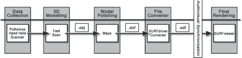
lour coded. The resulting surface model was export-ed as a .dxf file that was subsequently convertexport-ed to an .xdf graphics format so that it could read by SURF--driver software (Akuaware, Kailua, HI). This step in-cluded the addition of text rollover application as well as multiple language metafile application [20]. Final viewing of the resulting model, including roll-over text and audio, was achieved utilising SURF--viewer software (Akuaware, Kailua, HI)*.
Audio files
Audio files can be pre-recorded in three differ-ent languages (English, Japanese, Turkish) as .wav files utilising Audacity software (http://audacity. .sourceforge.net) and synchronised with the rollover text so that audio can be heard simultaneously with the display of the name associated with the ana-tomical object.
RESULTS
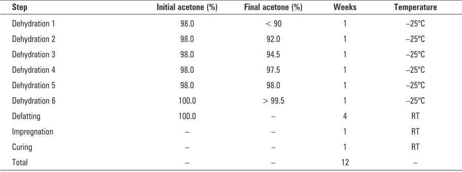
Table 1 provides the processing schedule for the plastination. Sufficient dehydration required six weeks of processing. Defatting required an addition-al four weeks while impregnation and curing con-sisted of approximately one week each. A total of 12 weeks of processing time was thus required to complete the plastination.
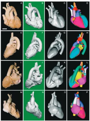
A plastinated heart specimen is viewed from va-rious perspectives (Fig. 2A, E, I, M). The specimen shows expanded chambers with significant surface detail including numerous vessels that remained patent as a result of the inr-seal injection. The great vessels remained open and pliant. Small structures including cardiac vascular branches were all clearly observable. Overall, the heart displayed the morpho-logy that could be expected from a well-dissected structure obtained through anatomical dissection.
A heart model resulted from hand-held scanning and surface reconstruction utilising Fast Scan soft-100:8] and placed in a medium sized vacuum
cham-ber attached to an oil-free two-stage vacuum pump (Labport, KNF, Neuberger) at 22o
C (RT).
Forced impregnation was achieved by applying a vacuum pressure to the chamber. The pressure was lowered (approximately 350 mm Hg) and adjusted several times throughout the day to maintain a con-sistent release of acetone bubbles from the speci-men. This process continued for four days until bub-ble release was no longer visibub-ble at the highest vacu-um pressure, at which point the specimens were con-sidered adequately impregnated.
Following impregnation, the heart specimens were removed from the vacuum chamber, placed on a wire rack so that excess polymer could drain, blotted with a paper towel, and wrapped to achieve further drying (4 days).
Specimens were lightly coated with Ct32 cross-linker (3 ¥ over 3 days) and then wrapped and placed in an airtight plastic container to achieve additional curing.
Computer modelling methodology
The graphics pipeline methodology follows Tu-nali et al. [20] (Fig. 1). Briefly, specimens were sus-pended by light monofilament line attached to a mounting stand. A handheld scanner (FastScan Cobra, Polhemus, Colchester, VT) attached to a Dell Vostro laptop computer was used to collect surface coordinates by repeated sweeps of the scan gun across individual specimens, consistently positioned at 10–15 cm from the surface of the specimen. The resulting coordinates comprised a wire mesh model that was output as an .obj graphics format file uti-lising Polhemus FastScan software. The wire mesh model was post-processed utilising Maya software (Autodesk, Fremont, CA). This model-polishing step comprised surface editing and rendering so that multiple cardiac structures were delineated and
co-Figure 1. Graphics pipeline for generating 3-D computer models from plastinated anatomical specimens.
Dehydration 4 98.0 97.5 1 –25°C
Dehydration 5 98.0 98.0 1 –25°C
Dehydration 6 100.0 > 99.5 1 –25°C
Defatting 100.0 – 4 RT
Impregnation – – 1 RT
Curing – – 1 RT
Total – – 12 –
All measurements performed with an acetonometer at 20°; RT — room temperature
ware (Fig. 2B, F, J, N). The model displayed promi-nent features present in the plastinated specimen; however, surface discontinuities were present. The model was imported into Maya Software, edited and rendered (Fig. 2C, G, K, O). Features that were lack-ing in the plastination were constructed and added in this step, e.g. superior vena cava. This process included segmenting the heart into its subcompo-nents. The heart model was exported as a .dxf graph-ics file and converted into .xdf format so that it could be imported into SURFdriver software where the model was checked for accuracy and its subcompo-nents colourised. Metafile information was includ-ed into the relevant folder so that audio recordings of anatomical names were synchronised with the rollover text and the final model was presented us-ing SURFviewer (Fig. 2D, H, L, P). The plastination (Fig. 2A, E, I, M) showed close qualitative conformi-ty with the final rendering (Fig. 2D, H, L, P).
Audio recordings included the anatomical names of the heart structures in English, Japanese, and Turkish for final presentation with SURFviewer soft-ware (Fig. 3A). Additional viewing tools facilitate feature removal (Fig. 3B), fading (Fig. 3C), or trans-lation (Fig. 3D). These options enable the user to examine more fully regions of interest.
DISCUSSION
The system described here relies on relatively in-expensive hardware including a hand-held scanner and Dell laptop computer. The graphics pipeline re-lies on software that has been shown previously to provide accurate and precise computer generated
anatomical models [10, 11]. Computational require-ments are minimal with final model rendering per-formed using a 200 MHz Intel Pentium processor, Windows XT OS, 64 MB RAM, and 1024 ¥ 786 screen resolution with 16-bit display. The surface consists of approximately 200,000 surface tiles that are viewed in real time display during manipulations. Thus, models are computationally modest and could be incorporated into electronic presentations utilis-ing PowerPoint or PDF utilities.
The final model displays features consistent with the plastinated specimen. Infusion of inr-seal assures patency of heart chambers and vessels. Adipose was not reconstructed so that the surface features could be more easily seen. Viewing tools enable the user to translate, hide, or fade superficial structures so that the underlying morphology can be seen. The models provide real time interaction that could prove useful for delivery in the gross anatomy lab. The incorpora-tion of plastinaincorpora-tion specimens into educaincorpora-tional learn-ing modules was recognized early in the development of the technique [14]. The current method extends ear-lier reports since the 3-D computer models can be in-corporated into an electronic laboratory dissection guide; for example, so that a student could manipu-late relevant structures thus providing a more realistic description of the dissection exercise as well as a rein-forcing spatial relationship seen in the cadaver. Simi-larly, the models could be incorporated into anima-tions providing more effective learning [8].
vascu-lar and nerve branches. As demonstrated here, small cardiac vascular branches are retained using the hand-held scanner. Similarly, topographic informa-tion, such as the anterior interventricular groove, groove for the cardiac veins, and small cardiac
vas-Figure 2. Comparison of a representative plastinated heart viewed from anterior (A), left lateral (E), posterior (I), and right lateral positions
(M) compared to corresponding computerised models following data collection by scanning (B, F, J, N), model polishing (C, G, K, O), and final rendering (D, H, L, P). Bar in A = 30 mm.
Figure 3. Rendering of the final object includes optional tools permitting rollover text with audio (A) as well as elimination (B), fading (C),
or translation (D) of selected structures. A rest button allows the user to return to the original model.
of weeks, this is still significantly less time than is required for generating cross-sectional tissue data-bases since the tissue sectioning step is avoided. Multiple specimens can be processed simultaneous-ly, facilitating selection of the optimal specimen for modelling as well as the opportunity to incorporate anatomical variation into an electronic presentation. Future work is being directed at incorporating the models into PDF-formatted presentations in gross anatomy laboratory guides.
ACKNOWLEDGEMENTS
Beth K. Lozanoff assisted with model polishing and organisation of illustrations. Ms. Atsuko Naka-niida assisted with the Japanese translation of au-dio files.
REFERENCES
1. An Po-C, Zhang M (1999) A technique for preserving the subarachnoid space and its contents in a natural state with different colours. J Int Soc Plastination, 14: 12–17. 2. Asadi MH, Mahmodzadeh A (2004) Ascaris
plastina-tion through S10 techniques. J Int Soc Plastinaplastina-tion, 19: 20–21.
3. Correia JAP, Prinz RAD, Benevides de Freitas EC, Pezzi LHA (1998) Labelling and storing plastinated speci-mens — an experience from Universidade Federal Do Rio de Janeiro. J Int Soc Plastination, 13: 17–20. 4. Doll F, Doll S, Kuroyama M, Sora MC, Neufeld E,
Lozanoff S (2004) Computerized reconstruction of a plastinated human kidney using serial tissue sections. J Int Soc Plastination, 19: 12–19.
5. Fasel JHD (1988) Use of plastinated specimens in edu-cation and clinical practice. Clin Anat, 1: 197–203. 6. Gao H, Liu J, Yu S, Sui H (2006) A new polyester
tech-nique for sheet plastination. J Int Soc Plastination, 21: 7–10.
7. Holladay SD, Hudson LC (1989) Use of plastinated brains in teaching neuroanatomy at The North Carolina State University, College of Veterinary Medicine. J Int Soc Plastination, 3: 15–17.
8. Jacobs J, Caudell T, Wilks D, Keep MF, Mitchell S, Buchanan H, Saland L, Rosenheimer J, Lozanoff BK, Lozanoff S, Saiki S, Alverson D (2003) Integration of
terized models of the anterior cranial base in young mice. Anat Rec, 234: 618–624.
11. Lozanoff S (1999) Sphenoethmoidal growth, mal-growth and midfacial profile. In: Chaplain MAJ, Singh GD, McLachlan JC eds. On growth and form: spa-tio-temporal patterning in biology. John Wiley and Sons, Chichester, pp: 357–372.
12. Park JS, Chung MS, Hwang SB, Shin BS, Park HS (2006) Visible Korean Human: its techniques and applications. Clin Anat 19: 216–224.
13. Pendovski L, Ilieski V, Nikolovski G (2004) Silicone plas-tination of a malpositioned long-term formalin-fixed green iguana. J Int Soc Plastination, 19: 40–42. 14. Purinton PT (1991) Plastinated brains used with
com-puter assisted learning modules for teaching veteri-nary neuroanatomy laboratories. J Int Soc Plastination, 5: 16–19.
15. Qiu MG, Zhang SX, Liu ZJ, Tan LW, Wang YS, Deng JH, Tang ZS (2003) Plastination and computerized 3D reconstruction of the temporal bone. Clin Anat, 16: 300–303.
16. Raoof A, Henry RW, Reed RB (2007) Silicone plastina-tion of biological tissue: room temperature technique — Dow™/Corcoran technique and products. J Int Soc Plastination, 22: 21–25.
17. Sora MC, Genser-Strobl B, Radu J, Lozanoff S (2007) Three-dimensional reconstruction of the ankle by means of ultrathin slice plastination. Clin Anat, 20: 196–200. 18. Spitzer V, Ackerman MJ, Scherzinger AL, Whitlock D (1996) The visible human male: a technical report. J Am Med Inform Assoc, 3: 118–130.
19. Spitzer VM, Whitlock DG (1998) The visible human dataset: the anatomical platform for human simula-tion. Anat Rec, 253: 49–57.
20. Tunali S, Farrell M, Sharp IC, Lozanoff BK, Doll S, Giesel F, Lozanoff S (2008) A multi-lingual computerized 3D anatomical instructional system for use in outreach education (unpublished data).
21. Uhl JF, Park JS, Chung MS, Delmas V (2006) Three-di-mensional reconstruction of urogenital tract from visi-ble Korean human. Anat Rec, 288A: 893–899. 22. von Hagens G (1985) Heidelberg plastination folder:
collection of technical leaflets for plastination. Anato-misches Institut 1, Universitat Heidelberg, Heidelberg, pp: 1–14.