Vol.7 (2017) No. 5
ISSN: 2088-5334
Blasting Design Without Subdrilling on Jointed Limestone
to Optimize Fragmentation and Blasting Cost
M.Taufik Toha
#, Bochori
#and Waluyo
* #Department of Mining Engineering, Faculty of Engineering, Sriwijaya University, 30662, Indonesia E-mail: [email protected], [email protected]
*
Graduate Study of Mining Engineering, Faculty of Engineering, Sriwijaya University, 30662, Indonesia E-mail: [email protected]
Abstract— Bench blasting operation on limestone opencast mining at PT. Semen Padang (Persero), Indonesia performed by electric blasting using coloumn loading system. Limestone deposit consist of three type of rock characteritics that are hard limestone, sugary limestone, and jointed limestone. In general, a good blasting design should implementing subdrilling to avoid toe. In this case of study the subdrilling is not need due to the present of many cracks caused by basalt intrusion. Blasting geometry that applied to blast the jointed limestone resulting blasting fragmentation that commonly relatively small in size (<60 cm) but still has some boulders (>60 cm) that caused by coloumn loading system where energy was concentrated in the bottom. Based on field observation of limestone blasting operation and productivity of excavator being used that is Excavator Hitachi EX 1100 with 5.4 m3 bucket capacity, can be
optimized. Especially from the view of drilling and blasting efficiency by modifying blasting geometry and explosive usage to optimize fragmentation to the productivity of excavator being used. Modification that performed is eliminate the sub drilling and change the explosives loading system from coloumn loading to deck loading (include amount of explosives and detonator being used). Based on result of modification, achieve decreasing of boulder percentage as much as 50.25% that is from 9.71% to 4.83% and increasing of excavator productivity up to 36.10% from 1,479 ton/hour to 2,013 ton/hour as well as decreasing blasting cost up to 17.18% from Rp 3,456/ton to Rp 2,862/ton.
Keywords— blasting design; jointed limestone; subdrilling; drilling and blasting efficiency.
I. INTRODUCTION
A. Background
Mining methods for jointed limestone at PT. Semen Padang (Persero), Indonesia is opencast mining with shovel-dump truck system. Limestone being mined consist of three type of characteristics those are hard limestone, sugary limestone, and jointed limestone. Strength of limestone is relatively high so that excavator can not dig it directly and have to conduct blasting operation.
Mechanism of rock breakage by blasting depend on many factors, one of them is the rock structure such as joints (cracks). The joints will act as reflecting plane, while the blasting wave that reach the plane will be reflected and its energy will decrease. So that blasting on large joint spacing rock will produce much big fragmentation (boulders). Otherwise, rock with close joint spacing will be an anvantage in blasting to produce less boulders.
The influence of rock structures (joint space) to the mechanism of rupture of the rock where the ground
vibrations caused by blasting with their joint activity can reduce the intensity of the pressure/compressive achieve free face. More and more areas of the joint, the smaller waves reaching compressive free face resulting in the fragmentation of boulders (Fig. 1).
In the blasting activities, explosives charging system coloumn loading with limited high of explosives column and column height stemming that is too thick, resulting in energy-blasting that is concentrated at the bottom of the explosion hole. For rock jointed structure, the blasting fragmentation results the top of explosive hole will be boulders. Beside the joint spacing (the distance between joints), the orientation of the joint is also an important factor to be considered in blasting operation.
Fig. 1.Mechanism of Rock Breakage [5]
Consequently when rocks have many crack with random orientation, the burden and spacing of blasting geometri can both be large. In this case, the drilling pattern can be square.
This research focussed on jointed limestone. Blasting resulted fragmentation by existing blasting geometry, still have boulders (>60 cm) that caused by coloumn loading system due to unequal energy distribution that mostly concentrated in the bottom of the blast hole. Boulders percentage will highly affect excavator productivity. To minimize boulders and increase drilling and blasting efficiency, blasting design for jointed limestone have to be done.
Blasting design include modification blasting geometry to eliminate subdrilling. Existing blasting geometry
use a 1.
2 m subdrilling, while modified geometry is without subdrilling. The rule of thumb for Stemming is about 0.7 – 1.3 times of the Burden. The actual conditon has 6.2 m stemming and Burden 4 m, so the ratio stemming to burden is 1.55. The ratio is exceed the rule of thumb, but fragmentation distribution still quite good with small number of boulder in the top.Other modification is the loading system, modify the loading system from the coloumn loading (bottom loading) to be deck loading (double deck). The modification of loading system include change in explosive and detonator usage
Generally, subdrilling should be implemented on bench blasting of rocks. The subdrilling is aim to avoid toe.Especially for jointed limestone in this case of study, due to physical and mechanic characteristics that have many cracks caused by geologic condition (basalt intrusion), so the subdrilling is not needed.Blasting without subdrilling will give advantages that are minimize blast hole depth, longer lifetime of drill bit and minimize explosive usage.
B. Geology Condition
PT. Semen Padang in West Sumatra lies in the part of the administrative area of the Municipality of Padang, District Lubuk Kilangan, in the Village Indarung. When measured from north east of Padang, West Sumatra, it has a length of ± 15 Km, geographically positioned at coordinates 100o 27'20''– 100o32 '12” East Longitude and 0o57'47 '' –01o00'48'' South Latitude. Indarung area located below the slopes of the Bukit Barisan Mountains, in this area there are several
rivers, namely Sungai Batang Arau, Sungai Batang Kuranji, Sungai Batang and Sungai Batang Kasumba Idas. Location Limestone quarrying Karang Putih Hill is in District Lubuk Kilangan, Village Batu Gadang (Fig.2).
Fig.2. Location of Study
Regionally area of study is located on the western slopes of the Bukit Barisan Mountains. The oldest known rock outcrops are Jura Tertiary age rocks. The rock group meta types of rocks, siltstones mixed with phyllite and tuff claystone with crystalline marble. Above the Pre-Tertiary rocks, Tertiary Quaternary Volcanic mineral aggregate is deposited unconformably.
Geological conditions of this area is a steep hill with a natural slope angle more than 45°. Limestone or marble and instrusion of igneous rocks (basalt, andesite and granitic) can easily found at Karang Putih Hill. Limestone located below the tuffaceous mudstone. Thickness of the layer is 100-350 m. In the south of the Karang Putih Hill there are basalt rocks. It can be estimated that in this area occurred basalt extrusion, the extrusion has resulted in the presence of efflorescence limestone into calcite with large size crystals. The oldest rocks that can be found in the area of Karang Putih Hill is a faint rustle of rock consisting of tuffaceous clay mixed with chert. The walls of the hill show indications of dissolution of rock through joints that indicated by the presence of caves.
Lithology of the young to the oldest found in KarangPutih Hill are as follows:
• Metasediments Limestone. blackish-gray - light gray colour, crystalline, massive, very fine-coarse grained (± 1cm). These rocks are interfingering to the faint rustle of clay stone, found many calcite veins and cavities, and crystalline. Distribution of this rock is dominant at the KarangPutih Hill. The rocks has experienced strong folding due to endogenous force in the general direction of Northwest to the Southeast. Sometimes encountered inserts tuff and silica, reddish white, smooth, massive, fresh until medium weathered.
cliffs and avalanches. Structurally, this tuffaceous mudstone has experienced strong folding. this can happen due to endogenous pressing but not over the elasticity limit.
• Intrusion Rocks. Intrusion rocks encountered in the area of study in the form of basaltic igneous rock. These rocks are gray-black, texture afanitic-faneric, very fine to medium grained, consisting of mineral feldspar, olivine, pyroxene (mafic minerals). This rock in general area fresh, very hard and compact. Distribution of the rocks are in the middle of the area of study.
• Alluvial Deposition,. The youngest outcrops encountered in area of study is alluvial deposits consisting of various kinds of rocks, generally found along the river of BatangIdas. These rocks are partially exposed as residual soil in northern area of Karang Putih Hill. The rocks is deposited unconformably over the tertiary rocks. Stratigraphy ofKarang Putih Hill can be seen on Fig.3.
Fig.3.Stratigraphy ofKarang Putih Hill [1]
The structure of the bedding has been seen on the limestone and rock faint rustle. Most bedding plane has a relatively same strike and dip, so it can be predict that the two groups of mineral aggregates are deposited within the same time and are in the same depositional environment. Faults and joints structure are found in this area, in general the fault structure can not be observed by naked eye, while the joint can be seen obviously and generally sloped perpendicular or over 80° and is open on the two separated areas and relatively wide. The fold structure of the anticline or syncline can be found at KarangPutih Hill
Jointed limestone is one of limestone characteristics with rock jointed structures and black colour (Fig. 4). These structures is caused by basalt intrusion.
Geotechnical data of limestone is average strength 162.19 kg/cm2and elasticity modulus is 123,192.7 kg/cm2 (Table I).
TABLEI LIMESTONE STRENGTH
D UCS Mod. Elasticity gr/cm3 kg/cm2 MPa kg/cm2 MPa
2.682 230.07 22.57 184,272.2 18,427.3 2.673 109.12 10.705 46,573.7 4,657.4 2.680 201.37 19.755 140,232.7 14,032.3 2.679 108.23 10.618 109,692.3 10,969.2
2.678 162.19 15.912 123,192.7 12,021.5
Fig.4.Jointed Limestone
C. Blasting Operation
Limestone mining method in open cast Karang Putih Hill implement benching system with excavator and dump truck as transport system. Generally mining activities include land clearing, stripping of overburden, blasting operation, hauling, crushing and sending the limestone to the cement plant.
Steps of blasting are drilling the blast hole, loading the explosives, cover the explosives hole using cuttings (stemming), connecting blasting circuit, blasting initiation.
Bench blasting system that is applied to the jointed limestone open cast mining with electric blasting system. Rotary drilling machine used Tamrock Drill crawlerbase CA 1100 with a 5.5 inch diameter bit. The drilling pattern used is rectangular zigzag. Explosives used is ANFO as a blasting agent, and Damotin 80% as a booster. Blasting geometri, explosive loading system and the amount of explosives used [2][3][4][5](Table II).
TABLEII BLASTING GEOMETRY
Condition Existing Modification
Loading System Coloumn Loading Deck Loading* Geometry BxSx(L-SD) 4 x 5 x (16.2-1.2) 4 x 5 (15-0)
Volume 300 m3 300 m3
ANFO (Kg) 125 100
Booster (Kg) 0.9 0.9
Number of Detonator 1 2
Powder Factor 0.31 0.26
Note :
Burden (B), Spacing (S), Hole Depth (L), Subdrill (SD) *Withoutsubdrill
Blasting geometry for jointed limestone to be modified without using subdrilling and change the loading system into the deck loading. These modifications affect the use of the amount of explosives and detonators (Table II).
With the modification expected distribution of fragmentation is more homogen due to blasting energy more evenly, so that the size of the boulders is reduced and excavators productivity increased and explosives cost reduced.
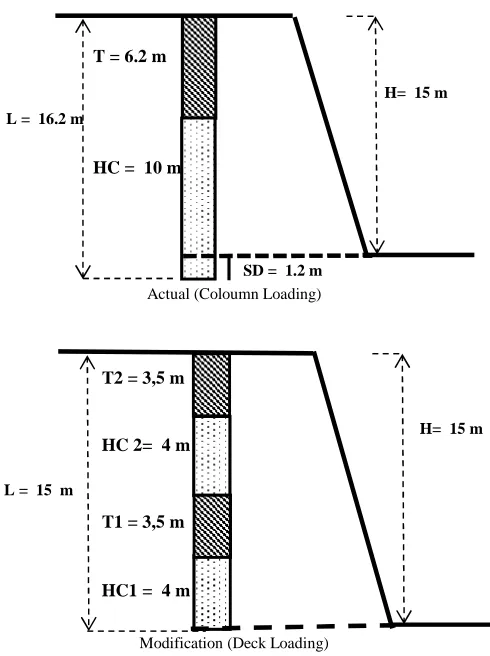
Illustration of blasting geometry and explosives loading system of existing and modification (Fig.5, Table II).
Actual (Coloumn Loading)
Modification (Deck Loading)
Note:
Stemming (T), Charge Coloumn (HC), Subdrilling (SD), Depth of Hole (L), Bench Height (H)
Fig. 5.Blasting Geometry
II. MATERIAL AND METHOD
The research method in this research is the collection of primary data and secondary data and then do the processing and analysis of data so it can be deduced. Primary data includes existing blasting geometry, explosives loading system, fragmentation photo and cycle time excavator.
Data of blasting geometry such as Burden, Spacing, Hole Depth, Stemming collect by direct measurement. Burden and spacing data are gain by measuring tape, while for hole depth and stemming, the measuring tape is equipped by plumb bob. Explosive usage are observed from the data record at explosive warehouse and explosives mixing facilities. Explosive loading system is observed directly at the blasting area while load the explosive to the blast holes.
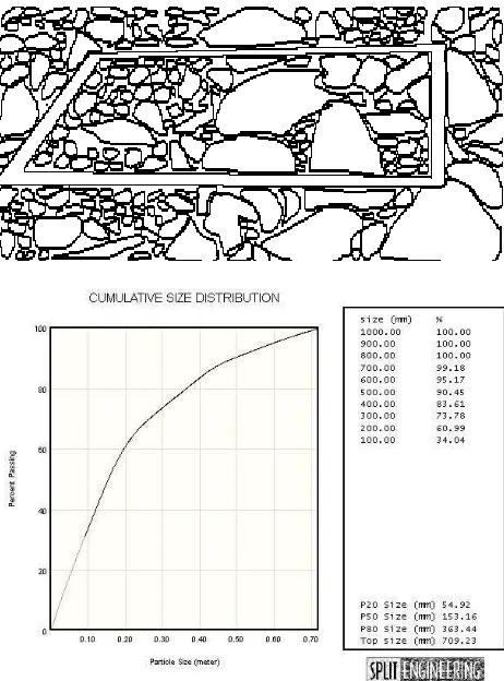
Observation of fragmentation is done by took the photograph of the fragmentation. The photo is took for upper part, middle part and lower part of the blasting area. A simple square ruler is included in every photo as a standard size to predict the size of fragmentation on the photograph. The dimension of square ruler is 1 m x 1 m which devided into 5 division respectively.
Secondary data such as geological of research areas, equipment specifications and prices of materials and blasting equipmentare provided by PT. Semen Padang.
Primary data was first taken from the existing blasting geometry in form of data fields, fragmentation result of the blasting photos [11] as well as cycle time excavator data. The data is processed to obtain the distribution of fragmentation, the cost of blasting and excavator productivity. Split Desktop 2.0 Demo Software used for fragmentation distribution data processing. Statistical methods used for cycle time data processing [7] in order to see the trendof the relationship between the fragmentation and the cycle time excavator [6].
Modification of blasting design [8] include modify blasting geometry to eliminate subdrilling and modify explosives loading system from coloumn loading to deck loading. After the modification of the geometry and the same type data retrieval. The results of data processing of the modified geometry compared to the results of the existing geometry [3][4][5][10][12] to obtain a conclusion and recomendation.
III.RESULT AND DICUSSION
A. Fragmentation of Blasting Result
Design of blasting geometry (without subdrilling) for jointed limestone is ([burden x spacing x (depth of hole – subdrilling)] = [4m x 5m x (15m – 0m)]. Fragmentation of blasting result using existing geometry can be seen at Fig 6, while Fig 7 shown the fragmentation of modified geometry. Both figures obviously shown that the modification geometry has smaller size than the actual geometry.
Calculation of boulder size fragmentation based on the blasting fragmentation photograph by using Split Desktop software Version 2.0 form Split Engineering show the percentage ofboulders are smaller in modification geometry. Boulder percentage is decrease from 9.71 % at existing geometry (Fig. 8) to be 4.83% at modified geometry (Fig. 9) or reduce 50.25%.
T = 6.2 m
HC = 10 m
SD = 1.2 m
H= 15 m
L = 16.2 m
HC 2= 4 m
HC1 = 4 m T2 = 3,5 m
T1 = 3,5 m
H= 15 m
Fig. 6.Photo Fragmentation of Actual Geometry
Fig. 7.Photo Fragmentation of Modified Geometry
Fig.8. Chart of Fragmentation Distribution of Existing Geometry
Fig.9. Chart of Fragmentation Distribution of Modified Geometry
The decrease fragmentation distribution of blasting results due to a more equitable distribution of energy blasting using deck loading system and rectangular zigzag drilling pattern and rock structure conditions of jointed limestone. This blasting fragmentation is suitable to the excavator bucket capacity of 5.4 m3. Blasting geometry design can be developed [burden x spacing x (depth of hole - subdrilling )] [5m x 5m x (15m - 0m)] with a square-zigzag drilling pattern to achieve fragmentation that suitable to the excavator bucket capacity of 5.4 m3 or bigger, In the implementation deck loading system required accuracy. By implementing deck loading system and zig zag drilling pattern the distibution of blasting energy can be more evenly vertically and horizontally.
B. Excavator Productivity
Blasted rock size should be suitable to the loader type and transport equipment that handling the rock. Blasted rock at Karang Putih Hill Quarry is loaded by excavator Hitachi EX 1100 that has 5.4 m3 bucket capacity. The excavator load the rock to the dump truck Catterpillar CAT 773 B that has vessel capacity up to 34.4 m3. Dump truck haul the blasted rock from the mining front to the crushing plant where the blasted rock being crushed to smaller size. The hauling distance is about 5 km.
geometry is about 0.36 minutes [7]. Using the average cycle time, excavator productivity is calculated and result productivity up to 1,479 ton/hour. Excavator performance is correlate to the fragmentation distribution [9] due to the boulder 9.71%. Whereas distribution cycle time of excavator for modified geometry tends dominantly shorter and the longest cycle time is up to 0.46 minutes with average 0.24 minutes (Fig. 11and Table IV) with productivity of excavator is up to 2,013.16 ton/hour (Table V) because of homogen fragmentation, boulder percentage decrease 4.83 % and excavator production increase 36.10%.
The above histrograms are created based on observation of cycle time of excavator and then the data distribute into classes to obtain the average cycle time and its trend. Histogram on Fig.7 and Fig. 8 show the strong relationship between distribution of fragmentation to the cycle time of excavator. Research result show that digging time for modified geometry is faster than that of the existing geometry due to a better fragmentation distribution.
Fig.10.Cycle Time Histogram ofActual Geometry
TABLEIII
HISTOGRAMOF CYCLETIMEFORACTUALGEOMETRY
Class Median (Xi)
Freq. (f)
Xi.f (Xi−X)
(
) .
.X X
i−
2f
0.24 - 0.28 0.26 6 1.56 -0.100 0.016 0.281 - 0.321 0.301 8 2.408 -0.039 0.004 0.322 - 0.362 0.342 14 4.788 -0.018 0.002 0.363 - 0.403 0.383 22 8.426 0.043 0.016 0.404 - 0.444 0.424 7 2.968 0.064 0.012 0.445 - 0.485 0.465 2 0.93 0.125 0.015 0.486 - 0.526 0.506 1 0.506 0.146 0.011
Total 60 21.586 0,074
Average = 21.586 / 60 = 0.360
Standard deviation = 21.586 074 . 0
= 0.0034
Fig.11. Cycle time Histogram of Modified Geometry
TABLEIV
HISTOGRAMOF CYCLETIMEFORMODIFIEDGEOMETRY
Class Median (Xi)
Freq. (f)
Xi.f (Xi−X)
(
) .
.X X
i−
2f
0.20 - 0.216 0.208 8 1.664 -0.03635 0.011 0.217 - 0.233 0.225 15 3.375 -0.01935 0.006 0.234 - 0.250 0.242 24 5.808 -0.00235 0.000 0.251 – 0.267 0.259 6 1.554 0.01465 0.001 0.268 – 0.284 0.276 4 1.104 0.03165 0.004 0.285 – 0.301 0.293 2 0.586 0.04865 0.005 0.302 – 0.318 0.310 1 0.310 0.06565 0.004
Total 60 14.661 0.031
Average = 14.661 / 60 = 0.244
Standard deviation =
661 . 14
031 .
0 = 0.002
C. Blasting Cost
Blasting geometry modification (without subdrill) and the deck loading system, decreasing ANFO usage by 25 kg and the addition of 1 piece of detonator, while the number of booster 0.9 kgremains same only divided into 2 parts
,
450greach. Jointed limestone blasting costs decreased by 17.18% from Rp 3,456/ton to Rp 2,862 /ton (Table V).
TABLEV
EXCAVATORPRODUCTIVITYANDBLASTINGCOST
Condition Existing Modification Boulder (>60 cm) 9.71 % 4.83 % Cycle Time (minute) 0.36 0.24 Productivity (ton/hour) 1,479 2,013.16
Cost (Rp/ton) 3,456 2,862
0 5 10 15 20 25
0,26 0,30 0,34 0,38 0,42 0,47 0,51
F R E Q U E N C Y ( f)
CYCLE TIME ( MINUTE) ACTUAL GEOMETRY [4 X5 X (16,2 - 1,2)]
0 5 10 15 20
0,26 0,29 0,33 0,36 0,39 0,43 0,46
F R E Q U E N C Y ( f)
IV.CONCLUSIONS
The advantages of this modification of blasting geometry without subdrilling are : reducing explosive usage, faster cycle time to drill a blast hole, increase drilling efficiency, longer drill bit lifetime and reduce drilling cost.
Blasting design for jointed limestone do not need subdrilling with geometry [burden x spacing x (hole depth– sub drilling)] = [4m x 5m x (15m – 0m)] with rectangular zigzag drilling pattern and deck loading system. Blasting fragmentation is suitable for bucket capacity maximum 5.4 m3. Deck loading system is more suitable for jointed limestone compared to coloumn loading system, because the blasting energy on the deck loading is distributed more evenly so that boulders percentage relatively decrease to 50% and excavator productivity increase up to 36.10% and blasting cost decrease 17.18%.
Blasting design jointed limestone for excavator with bucket capacity more than 5.4 m3, for example for excavator Hitachi EX 2000 with bucket capacity 10,5 m3can be applied blasting geometry [burden x spacing x (hole depth – subdrilling)] = [5m x 5m x (15m – 0m)] with deck loading system and square-zigzag drilling pattern.
Basically in blasting geometry design, the size of resulted fragmentation should be suitable to the bucket capacity of excavator.
ACKNOWLEDGMENT
On this occasion, we would like to express our gratitude to the Management and Employee of the Department of Mines PT. Semen Padang (Persero) for the opportunity to conduct field research and supporting data
.
REFERENCES
[1] PT.Semen Padang (Persero).Keadaan GeologiIndarung Sumatera Barat; 2015.
[2] Ditta L, Nurhakim MU, Marselinus UD, Excelsior TP. Studi Teknis Penentuan Geometri Peledakan dan Powder Factor (PF) pada Pembongkaran Bijih Besi di PT. Putera Bara Mitra, Desa Mentawakan ulya, Kec. Mantewe, Kab. Tanah Bumbu, Kalimantan Selatan. Journal Geosapta Vol. 1 No. 1 ;Juli 2015. 29p.
[3] Victor MB. Optimization of Blasting Design Parameters on Open Pit Bench a Case Study of Ncanga Open Pits. International Journal of Science & Technology Research. China : 2015. volume 4, ISSN 2277-8616.
[4] Sang HC and Katsuhiko K. Rock Fragmentation Control in Blastig. Material Transactions. Japan; 2004. Vol.45, No.5.
[5] Kirsanov AK, Vokhmin SA, Kurchin GS. A Brief History of the Development of Blasting and the Modern Thering of Rock Breaking. Journal of Degraded and Mining Lands Management; July 2016.ISSN: 2339-076X (p), Vol.3, Numb.4.
[6] Safarudin, Purwanto, Djamaludin. Analisis Pengaruh Geometri Peledakan Terhadap Fragmentasi dan Digging Time Material Blasting. Jurnal Penelitian Enjiniring; November 2016 Vol. 20 No. 2, 54-62.
[7] Sudjana. Metode Statistika.Bandung; Tarsito, 2005
[8] Singh PK, Roy MP, Paswan RK, Sarim MD, Kumar S, Jha RR. Rock Fragmentation Conrol in Opencast Blasting. Journal of Rock Mechanics and Geotechnical Engineering: 2016 Vol 8 No. 2,;225p. [9] Choudary BS and Kumar P. Fragmentation vis-a-vis Excavator Cycle
Time – A Case Study. Indian Mining and Engg. Journal; June 2013, Vol. 52. No.6, 1p.
[10] Menzhulin MG, Yu KA, Afanasiev PI, Tyulkin SA. Drilling and Blasting Parameter for Gavrilovo Granite Deposite. Mining Journal; Januari 2017, 1p.
[11] Siddiqui FI, Ali SMS and Behan MY. Measurment of Size Distribution of Blasted Rock Using Digital Image Processing. JKAU. Pakistan; 2009. Eng, Sci Vo.20 No.2.
![Fig. 1.Mechanism of Rock Breakage [5]](https://thumb-us.123doks.com/thumbv2/123dok_us/10030101.1989764/2.595.48.275.53.221/fig-mechanism-of-rock-breakage.webp)