COMPUTATIONAL FLUID DYNAMICS MODELLING OF AN
AERODYNAMIC REAR SPOILER ON CARS
T. D. Ipilakyaa
1,*, L. T. Tuleun
2and M. O. Kekung
31,2,3,
D
EPARTMENT OFM
ECHANICALE
NGINEERING,
U
NIVERSITY OFA
GRICULTUREM
AKURDI,
B
ENUES
TATE,
NIGERIA
Email addresses:1[email protected], 2 [email protected], 3 [email protected]
ABSTRACT
At speeds greater than 100km/h, the performance, handling, safety, and comfort of a car are significantly affected by its aerodynamic properties. In a bid to improve on the aerodynamics of cars, rear spoilers/wings are increasingly being used both on race and passenger cars. This paper employs Computational Fluid Dynamics (CFD) techniques to investigate the aerodynamic effects of rear spoilers on Drag and Lift of a car. In carrying out this study, a rear spoiler already designed was used. The spoiler was modelled in CAD software (Autodesk Inventor professional) along with a model car that it will be mounted upon. Two cases were set; the car alone without the rear spoiler (case 1) and, the car with the rear spoiler assembled on its rear deck (case 2). These two cases were imported into CFD software (ANSYS Fluent 15.0) for simulation. The Drag and Lift on the two cases were obtained in terms of their coefficients from the analysis. From the results obtained, it was observed that using a wing type rear spoiler led to an increase in downward force (negative lift), and a consequent increase in drag on the car. The increased downward force on the car will reflect in an increased cornering ability and stability of the car at high speed, while the attendant Drag entails increased fuel consumption. From the amount of downward force generated compared to Drag, and given that safety is put first above going faster; the benefits of using the rear spoiler outweighs that of not using it.
Keywords: Aerodynamics, Simulation, Drag Force, Lift Force
1.0 INTRODUCTION
Vehicle’s aerodynamic performance has long been a paramount concern to automobile design engineers. As a vehicle moves through air, at top speed the drag and lift forces on the vehicle becomes of significant effect to the vehicle’s aerodynamic performance. These tend to negatively influence the performance, handling, stability and fuel efficiency of the vehicle [1]. To improve on the aerodynamics of vehicles, the design of external aerodynamic accessories to vehicles which can be attached externally to a vehicle to improve its aerodynamic performance and make for easier handling and fuel efficiency is employed. Thus extra parts and design structures are added to the body of the vehicle such as Rear Wings/Spoilers, Lower Front and Rear Bumpers, Air Dams, and many more aerodynamic accessories [2]. These aerodynamic devices take advantage of the airflow around the moving vehicle in modifying the flow situation to such that benefits the user as against it incurring extra cost in terms of increased fuel consumption and vehicle maintenance. The Rear wing/spoiler is one of the major
aerodynamic components used to alter the airflow around a vehicle to reduce drag, prevent lift and even to generate down force as in the case of the rear wing. In the design of rear spoilers for vehicles, Computational Fluid Dynamics (CFD), complements experimental and track testing in providing optimum designs. As stated by [3], external aerodynamics simulations using Computational Fluid Dynamics (CFD) are presently well established tools in the product development process for the automotive and aerospace industries. CFD simulation technology helps engineers to understand the physical phenomena taking place around a design and provides an environment to optimize the performance with respect to certain criteria without the need for the costly testing of multiple prototypes. In the automotive domain, the aerodynamic forces of lift and drag have strong impact on the vehicle and CFD provides a leverage to analyse these forces and determine an optimum design. CFD also serves as a powerful graphical tool for visualizing flow patterns that can give insight into flow physics
Vol. 37, No. 4, October 2018, pp.
975 – 980
Copyright© Faculty of Engineering, University of Nigeria, Nsukka,Print ISSN: 0331-8443, Electronic ISSN: 2467-8821
that otherwise would be very difficult and costly to discover experimentally, if possible at all [3].
This work is about carrying out further work on an already existing spoiler designed by Edo [1]. The study aims at improving on the productivity of his work by carrying out CFD analysis of his work using commercial CFD software ANSYS Fluent® and possibly propose a design modification for optimization.
1.1 Aerodynamic Concept of Drag and Lift
When a fluid moves over a solid body, it exerts Pressure forces normal to the surface and shear forces parallel to the surface of the body. The resultant of the pressure and shear forces acting on the body is particularly of interest. The component of the resultant pressure and shear forces that acts in the flow direction is called the Drag force and the component that acts normal to the flow direction is called the Lift Force as shown in Figure 1 below.
Figure 1: Forces Acting on an Aerofoil [3]
Aerodynamic drag force acts on the vehicle body resisting its forward motion. This force is an important force to be considered while designing the external body of the vehicle, since it covers about 65% of the total force acting on the complete body [4]. Since drag is dependent on the square of velocity, it is predominant when objects travel at very high speeds. It is the most important aerodynamic force to study because it limits both fuel economy of a vehicle and the maximum speed it can travel [1]. Aerodynamic Lift force on the other hand, causes the vehicle to get lifted in air as applied in the positive direction, thereby reducing the frictional force between the tires and the road, causing dramatic handling difficulties, stability problems and general fuel efficiency issues. Whereas, it can result in excessive wheel down force if it is applied in the negative direction. The drag and lift forces can be respectively calculated from equations 1 and 2 below.
( )
( )
Where, D is the Drag force, CD is Drag coefficient, L is Lift force, CL is the Lift coefficient, A is frontal area of the vehicle, ρ is the Air density, and V is the Vehicle’s velocity.
1.2 The Rear Spoiler/Wing
A spoiler is an aerodynamic device attached to an automobile rear boot whose intended design function is to ‘spoil’ unfavourable air movement across a body of a vehicle of some kind in motion. Spoilers are widely used on sedan type cars. These aerodynamic aids produce down force by creating a "dam" at the rear lip of the trunk. This can result in improved vehicle stability by decreasing lift or decreasing drag that may cause unpredictable handling in a car at high speed. Spoilers are often fitted to race and high performance sports car, although they have become common on passenger vehicles as well due to their importance [5]. Wing type spoilers make use of an inverted aerofoil and are used for generating down force at the rear of the vehicle.
1.3 Computational Fluid Dynamics (CFD)
Computational Fluid Dynamics (CFD) is the branch of fluid dynamics providing a cost-effective means of simulating real flows by the numerical solution of the governing equations [6].It uses numerical methods and algorithms to solve problems that involve fluid flow. [7] defined CFD as a set of numerical methods applied to obtain approximate solution of problems of fluid dynamics and heat transfer. CFD involves creating a computational mesh to divide up real world continuous fluids into more manageable discrete sections. The governing equations for fluid flow can then be applied to each section individually, but as the properties of each section are inevitably linked to its neighbouring sections, all the sections can be solved simultaneously until a full solution for the entire flow field can be found. This method obviously requires a huge amount of computational power, nevertheless with the advancement of modern computing, solutions that would take months to compute by hand can now be found in seconds using nothing more than an ordinary desktop or laptop computer [3].
2.0 Methodology
The following procedure was employed in the computational fluid dynamics modelling of an aerodynamic rear spoiler on cars:
I. Modelling of Rear Spoiler according to specifications.
III. Assembly model of car with the rear spoiler (i.e. case 2).
IV. CFD analysis for drag and lift on case 1 (vehicle only).
V. CFD analysis for drag and lift on case 2 (vehicle + rear spoiler).
VI. Comparing results of case 1 and case 2.
2.1 Modelling of the Spoiler
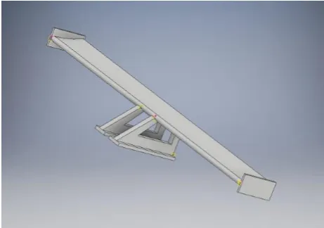
The rear spoiler was modelled according to specifications given by James Adams Edo [1]. The spoiler is a wing type spoiler in that an aerofoil was used in the design (basically an inverted aerofoil). Figure 2(a) shows the aerofoil shape while Figure 2(b) is a CAD printing of the completed rear spoiler. The design parameters are given below:
Selig 1223 Aerofoil, Span = 1.7m, Chord = 0.20m, Camber = 11.92% chord, Thickness = 3.071% chord, Angle of attack = 10.0 degrees.
2.2 Modelling Car and Car/Spoiler Assembly
The spoiler was designed for a passenger vehicle sedan car. Autodesk Inventor has been used to model a sedan car for the spoiler to be mounted upon for analysis. The
main parameter considered in designing the car in relation to the spoiler is the span of the spoiler which is 1.7m. Two cases were set for analysis purpose; case 1 (vehicle only) as shown in Figure 3(a) and case 2 (vehicle + spoiler) as shown in Figure 3(b).
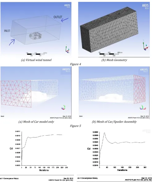
2.3 CFD Analysis of Case 1 and Case 2 on ANSYS Fluent The CAD models of both case 1 and case 2 were imported individually into ANSYS Fluent® 15 and a virtual air box enclosure which represents the wind tunnel in real life is created around the model as shown in Figure 4(a). The enclosure volume was meshed using tetrahedron elements (Figure 4b), and to capture the boundary layer effect an inflation of 20% was created near the car surface. For both case 1 and case 2, the realizable k-ɛ turbulence model was used for the analysis at steady state. The boundary conditions were chosen such that the flow field most closely depicts the real world scenario of a vehicle moving through air under normal atmospheric conditions. The inlet velocity used is 40 m/s, the gauge pressure was set as 0 Pascal, wall zones were depicted as No slip, the fluid type was set to be air at a density of 1.175 kg/m3 and a kinematic viscosity of . .
(a) Aerofoil shape used in the design of spoiler. (b) 3D CAD model of the Rear Spoiler Figure 2
3. RESULTS AND DISCUSSION
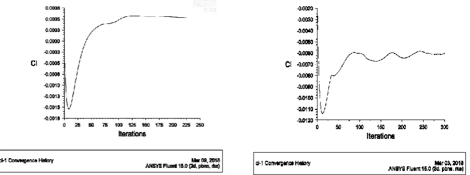
For case 1, 250 iterations were performed using a second order upwind discretization until it reached the convergence criteria, while 300 iterations were performed for case 2. From the plots of convergence history, the coefficient of drag CD for case 1 (vehicle
only) is given to be 0.001 and that for case 2 (vehicle + spoiler) is given as 0.0045. Similarly, CL for case 1 is given to be 0.0005 and that of case 2 as -0.006. The negative sign indicates negative lift (or down force). Values are summarised in Table 1.
(a) Virtual wind tunnel (b) Mesh Geometry
Figure 4
(a) Mesh of Car model only (b) Mesh of Car/Spoiler Assembly
Figure 5
Figure 7: Lift coefficient (CL) convergence history for case 1 and case 2 respectively.
Table 1: Table of Result
S/N Parameter Vehicle only Vehicle + Spoiler
1. CD 0.0010 0.0045
2. CL 0.0005 -0.0060
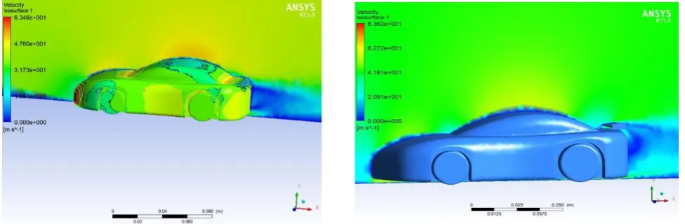
In comparing the drag and lift coefficients of case 1 and case 2, the aerodynamic effect of using the rear spoiler can clearly be seen. The drag coefficient showed an increase from 0.001 to 0.0045; and the lift coefficient decrease from 0.0005 to -0.006 on addition of the spoiler. This is in agreement with [2]. The high drag experienced on addition of the spoiler is a direct backlash from the high amount of down force (negative lift) produced. This is because the spoiler is a wing type spoiler (an inverted aircraft wing) design from an aerofoil to produce down force. It is a known fact that increased down force contributes to an increase in pressure drag. From the pressure and velocity contours for both cases shown in Figures 8 and 9, the aerodynamics of the car and spoiler can further be understood. The pressure contour diagram for both
cases clearly show the stagnation point in front of the vehicle as air is almost stagnant in those regions. By Bernoulli’s principle a high pressure region corresponds to a low velocity region as seen in the velocity contours. The effect of the rear spoiler in generating down force can be noticed in Figure 8, as the spoiler replaces a very low pressure region at the trunk of the car (responsible for lift) with a high pressure region coupled with the down force generation of the aerofoil. To explain why the spoiler lead to an increase drag, comparing the wake region of both cases would do. From the velocity contour of case 1 and case 2 (Figure 9), it can be seen that the use of the spoiler lead to an increase wake region behind the vehicle. Wake depicts the disturbance that occurs behind a body as it moves in fluid. The attached spoiler obstructs the localized airflow and hence prevents the air from being pulled downward which would otherwise generate turbulence and low pressure air pockets behind the vehicle contributing to pressure drag.
(a) Velocity contour for case 1 (b) Velocity contour for case 2 Figure 9
4. CONCLUSION
The computational analysis of an aerodynamic rear spoiler was successfully carried out employing techniques of Computational Fluid Dynamics (CFD) by using CFD software, ANSYS Fluent. The analysis has revealed the aerodynamic performance of the said rear spoiler when it is mounted on a passenger sedan car to be used at high speed. From the analysis, it is observed that with the use of the rear spoiler the drag coefficient (CD) increased from 0.0010 to 0.0045, which is a 350% increase in drag. Also, the lift coefficient (CL) reduced from 0.0005 to -0.006 which shows a 1300% lift reduction. The results obtained are in consonance with established findings in this area. From relevant literatures, it is known that the use of wing type rear spoilers has the backlash of increased drag on the vehicle, and an advantage of a desired greater down force (negative lift) on the vehicle. This is mostly the case with race cars. The high percentage disparities though, are not consistent with established findings. They are largely due to lack of sufficiently converged solutions which is as a result of the time and Central Processing Unit consuming nature of the solutions. But the directions of the results are pointers to the effect of the rear spoiler on the vehicle.
In general, the analysis has shown the rear spoiler to be suitable for high speed vehicles such as race cars, for only then will its high down force generation capacity be fully utilized. It is known that having down force (negative lift force) generates the following advantages:
Increases the tires capacity to produce cornering force;
Stabilizes the vehicle at high speed;
Improves braking performance;
Gives better traction.
Having more down force than having less drag can be more important for passenger cars since driving safely is always number one priority. Also, with a suitable and efficient down force device as this, the self-weight of the vehicle can conveniently be reduced without consequence and this will compensate for the increased drag in terms of fuel consumption.
References
[1] James A. E. “Design of an Aerodynamic Rear Spoiler”. Mechanical Engineering Undergraduate Project. University of Agriculture, Makurdi, 2013. [2] Naveen K., Lalit N.V., Narasimha R. and Sri Ram, Y.
“Investigation of drag and Lift Forces over the Profile of Car with Rear Spoiler using CFD”,
International Journal of Advances in Scientific Research, Vol. 1, Issue 8, 2015, pp 331-339.
[3] Leary, J. Computational Fluid Dynamics Analysis of a Low Cost Wind Turbine. Mini-Project Report. University of Sheffield. 2010.
[4] Cakir, M. “CFD study on aerodynamic effects of a rear wing/spoiler on a passenger vehicle”. Mechanical Engineering Masters Theses Paper 1. Santa Clara University, 2012.
[5] Ridhwan, B. C. Z. Aerodynamics of Aftermarket Rear Spoiler. Undergraduate Project, University Malaysia Pahang, 2008.
[6] Abdulnaser, S. “Computational Fluid Dynamics, Ventus Publishing ApS. 2009. www.bookboon.com. Accessed on May 2, 2018.
![Figure 1: Forces Acting on an Aerofoil [3]](https://thumb-us.123doks.com/thumbv2/123dok_us/9998729.1987515/2.595.58.284.319.458/figure-forces-acting-aerofoil.webp)