The Study of High Current Charging and
Sawtooth Wave Equalization Method for Ni-MH
Capacitance Power Battery
Jiagan Li
Shandong Jiaotong University, Weihai, China Email: [email protected]
Abstract—To realize electric bus's quick charge, which choose nickel metal hydride (Ni-MH) capacitor battery as its power system in Zibo, then analysis and design quick charge system. Using the Matlab/Simulink measures the power grid harmonic content, and according to the Ni-MH capacitor battery's short-time large current charge characteristics, selecting voltage controller method as charging terminate parameters. Eventually, realize the electric bus's quick charge through the field experiment. At the same time, in the use of the Ni-MH capacitance power battery, the performance difference of battery cells makes the voltage unbalance in the charge and discharge processes, which traditional balanced method also needs long time. This paper studies the quick charge method of the power battery, and proposed a sawtooth balance strategy which can increase the battery life. Based on the proposed charge control strategy, and test on Zibo electric bus for balance charging. Experimental results show its feasibility and effectiveness.
Index Terms—quick charge, equalization control, sawtooth wave, battery management system
I. INTRODUCTION
For a long time, the traditional battery has the problems of small capacity, long charging time and memory effect. The power system of an electric vehicle is usually composed of multiple battery monomers in series. Due to different processes such as battery internal resistance and working environment, the initial capacity of each single battery is different to some extent, and the imbalance of battery voltage will be further aggravated in the future charging and discharging process [1]-[7]. In the process of use, the actual amount of electricity released by the battery is determined by the cell with the smallest capacity, and the whole battery pack will not continue to work normally when the cell is discharged or overdischarged [8], [9].
Currently, Ni-MH capacitor batteries have no memory effect of charge and discharge, allowing hundreds of thousands of charge and discharge without any loss of capacity. Now in Zibo Ni-MH batteries in electric bus full capacitance voltage is 720v, short charging current is 300A, for example, in order to achieve high current fast
Manuscript received April 12, 2019; revised August 2, 2019.
charging and battery voltage equilibrium, this paper analysis the existing type charging machine, finally select 2 series 12 pulse rectifier circuit as an electric buses rectifier system to meet the design requirements.
II. THE DESIGN OF CHARGING SYSTEM
A. Analysis of Existing Types of Charger
At present, electric vehicle chargers are mainly divided into three categories according to their working principles [10]-[15]: the first type of charger is composed of power-frequency transformer, uncontrollable rectifier and chopper, which is an early product. Injection of power grids harmonic current is too big, not suitable for access to the utility grid. The second charger by three-phase uncontrolled rectifier device and high frequency transformer isolated DC/DC converter. The characteristics of grid side current harmonic is large (about 30%) and low transformation efficiency. This kind of charger, though harmonic content high, but the cost is low, and is the mainstream of the charger on the market, most existing charger research results also focused on this kind of charging machine. The third type of charger by three-phase PWM rectifier and high-frequency transformer isolated DC/DC converter. But PWM rectifier charger due to technical problems such as complexity, reliability and cost, although it has appeared in the market, it is seldom used and relevant research results are few. Based on the above analysis, this paper analyzes the selection of rectifier system, implementation of control output, network side harmonic content and on-site charging effect on the basis of reducing harmonic content and improving power, so as to make it meet the design requirements.
B. The Design of Rectifier Circuit
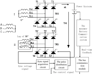
pack each charging pressure of about 1v) beforehand, so we choose 2 series 12-pulse rectifier circuit. Fig. 1 for charging system schematic diagram, in order to make 2 of 12-pulse rectifier rectifier bridge instantaneous output voltage on the phase stagger 30°, two bridge circuit of
power supply by 1 three winding transformer power supply, a secondary side of two winding into a star, One by one into a triangle, triangle connection group output line voltage hysteresis star connection set of output line voltage 30° [16].
Power Systerm
The monomer Battery
Communi-cation system
Real-time feedback
The bus communica
-tion module The control signal
The pulse distribution
circuit Sync signal
acquisition circuit Sync voltage
signal Lag of
Figure 1. Sawtooth equilibrium system schematic diagram.
As shown in Fig. 1, the rectifier circuit consists of two three-phase full-control rectifier Bridges in series, so the output DC voltage is twice that of the single bridge, which improves the DC output of the rectifier system, and the output voltage is about 1000V, meeting the requirements of charging voltage.
III. THE DESIGN OF BALANCE SYSTEM
A. Overall System Structure
The working principle of Equalization is shown in Fig. 2. Equalization system and vehicle management system communicate with each other, and Equalization system directly with the vehicle detection system to realize the
control of the equilibrium system, which also realize the intelligent control and save the cost. Vehicle detection system consists of the monomer battery collection system, the bus communication module, ECU battery collection system, CAN communication system, in which monomer cell collection system consists of a voltage signal acquisition, the current signal acquisition, signal acquisition temperature, pressure signal acquisition module.
Acquisition signal through the bus communication module, calculated by the ECU battery control system, processing, and then through the CAN communication system and external balance system of communication, which in turn by the controller for battery charge balance.
The monomer
Battery
Communi-cation system
The bus
communi-cation module
ECU battery
collec-tion system
CAN
communi-cation system
The sawtooth equilibrium system Power Systerm
The controller
Upper machine
B. The Principle of Sawtooth Equalization
Firstly, the charging device uses constant current to charge in series, when the signal battery acquisition system detected signal battery voltage has charged enough, then stops constant current charging, using sawtooth equilibrium to charge. As the charging process, when required by the monomer voltage to the voltage value will no longer rise but the battery internal composition, producing a small quantity of heat.
So, Positive:
2OH-2e→1 2
O2+H2O
Negative:
H2O+2e→H2+2OH
Composite:
H2+1 2
O2→H2O+heat energy
In the external air cooling conditions, the battery temperature remains substantially constant. Hydrogen and oxygen can easily recombination to generate water inside the battery. The recombination rate quickly, which can make the oxygen concentration is not more than a few parts per thousand in the battery internal, and makes the gas pressure inside the cell remains the same [17], [18]. With other low voltage value of the monomer the battery, it can achieve charging rapidly, which achieve ultimate purpose of equalization. The sawtooth equilibrium waveform is shown in Fig. 3.
0 U / V
T / S Sawtooth wave
The average voltage of sawtooth
The average voltage of the battery pack
Figure 3. The sawtooth equalization waveform.
C. The Design Sawtooth Equalization System
Sawtooth equilibrium system schematic diagram is shown in Fig. 1. The total voltage of electric bus power system is 700V, which has high battery voltage and large capacity. So choose the twofold series three-phase 12-pulse rectifier circuit as the main circuit to realize sawtooth charge quickly.
The bus communication module of Sawtooth wave balanced is composed of ECU battery control system, CAN communication system, controller and so on, which is shown in Fig. 2. When the collection system of monomer battery detected monomer battery voltage achieve requirements, then communication transmission regulation control unit sends a signal which realize the control of pulse distribution circuit.
Then communication transmission control part of the signal control to realize the control of pulse distribution circuit, so as to realize the thyristor trigger for the sawtooth wave output. When the collection system of monomer battery detects a monomer battery voltage reaches the charging requirements, communication transmission control part of the signal control to realize the control of pulse distribution circuit, so as to realize the thyristor trigger for the sawtooth wave’s output.
IV. SIMULATION AND TESTING
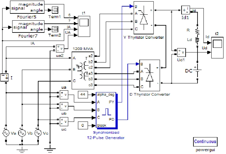
A. Simulation of Harmonic Content
In the context of Matlab/Simulink, the harmonic content of the charging system of electric bus is simulated and analyzed. The simulation model is shown in Fig. 4.
Two test points are set in the simulation model, and the waveforms of each test point are described as follows.
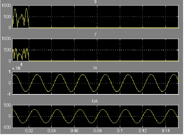
Oscilloscope t1 to select the four input signal, respectively for web side voltage, current and the network side 5, and 7 harmonics, the waveform diagram as shown in Fig. 5. IT can be seen from the waveform in the network side of pulse voltage and current is small, at the same time network side in 5, and 7 times in line current
harmonic amplitude is very small, almost zero, realized with harmonic suppression, reduces the network side harmonic content.
The oscilloscope t2 is the DC current and voltage waveform output by rectifier, as shown in Fig. 6. From the simulation waveform, it can be seen that: the DC voltage pulsates 12 times in one cycle, and compared with the three-phase and six-pulse rectifier circuit with the same incoming voltage, the dc voltage output by the 12-pulse rectifier circuit is doubled. After being processed by flat wave reactor, the DC current pulsation of rectifier output is small, which meets the working requirements of the charger we designed.
Figure 5. The waveforms of 5 and 7 harmonics and grid side current and voltage.
Figure 6. The waveforms of 12 pulse rectifier output current and voltage.
B. Analysis of Charging Effect of Electric Bus
Common charging termination control methods include: Timing control, voltage control, current control and comprehensive control [19]-[21]. We are here to choose voltage control method, namely the highest battery voltage control Vmax. Electric bus power system is made up of monomer Ni-MH capacitance in series with a battery, the design of each monomer battery limit of 1.5 V, lower limit charging voltage of 1.0V, in power system
full voltage is 720V, we according to the characteristics of Ni-MH capacity batteries and electric bus power system design requirements, to provide the rated current is 300A short-term quick charge, direct current (DC) of the following is the charging data in Table I.
is about 216KWh. Considering the discharge depth and other factors, the pre-charging energy is about 72KWh. That is to say, the charger can fully charge the battery pack in about 20 minutes, which greatly shortens the charging time and realizes the rapid charging of electric buses.
TABLEI. FIELD CHARGING DATA
Charging time (min)
Battery voltage (V)
Charging current
(A)
charging amount (KWh) 1 697 300 3.1 2 706 300 6.6 3 712 300 9.9 4 716 300 13.7 5 720 300 17.4 Note: the battery voltage (V) is taken as the parameter of charge termination, and the charge amount (KWh) represents the amount of charge of the battery pack.
C. The Analysis of Balanced Charging Effect of Electric Bus
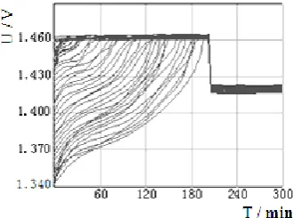
The parameters of monomer Ni-MH battery capacitor electric bus is 1.2V/300Ah, the highest monomer battery charge voltage is 1.460V. The batteries charging voltage waveform of without sawtooth balanced circuit and with sawtooth equalization circuit are shown in Fig. 7 and Fig. 8.
Figure 7. The batteries charging voltage waveform of without sawtooth balanced circuit.
Figure 8. The batteries charging voltage waveform of without sawtooth balanced circuit.
It is shown in Fig. 7, due to differences in manufacturing process, there exist deviations in voltage of each battery. When charging the difference is further amplified, so that the deviation of the battery voltage is becoming more and more bigger. In the late charging, the voltage of batteries are serious imbalance, one part of the batteries are overcharge and the other part of the batteries are charging very poor. The results shown in Fig. 8 that after using sawtooth wave equilibrium strategies, as the charging process, the battery voltage difference gradually narrowed, in the late charge achieve good balancing effect, thus can improve the performance of the battery pack and cycle life.
V. CONCLUSION
This paper analyzes and designs the quick charging system for the electric bus with Ni-MH capacitor battery as the power system in Zibo city. The influence of the inconsistency of the power battery on the cycle life of the battery is analyzed, and a sawtooth wave equalization method which can realize the quick charging of the Ni-MH capacitor power battery and eliminate the voltage inconsistency is proposed. Finally, the electrical simulation of the harmonic content on the grid side was carried out by Matlab/Simulink. The experimental results showed that the harmonic content of the power grid was reduced. The experimental results show that the sawtooth wave equalization method is effective and the charging system has a broad application prospect.
REFERENCES
[1] G. L. Wu, C. B. Zhu, and Q. Q. Chen, “Research on a piecewise mathematical model with decay factor for battery,” Electric
Machines and Control, vol. 13, no. 1, pp. 188-192, 2009.
[2] Y. Lin, “Design of intelligent charging management system for nickel metal hydride battery,” Coal Mine Machinery, Feb. 2018. [3] J. J. Liu, “Prediction method for quick charging power of
crystalline nickel metal hydride battery pack,” North China University of Technology, May 2016.
[4] B. Liu, “The study on nickel hydrogen battery storage and performance attenuation for hybrid electric vehicle,” Chongqing University, May 2015.
[5] S. Y. Li and Z. L. Dou, “Intelligent nickel metal hydride battery charging circuit design,” Laboratory Research and Exploration, July 2014.
[6] C. Feng, “High voltage battery charging system for electric vehicle,” North China Vehicle Research Institute, May 2017. [7] H. Sun, “A fast charger design,” Technology Outlook, Nov. 2015. [8] J. Li, “Talk about the correct charge and maintenance of the
battery,” Agricultural Machinery Use and Maintenance, vol. 1, 2018.
[9] X. H. Xiao, X. J. Zeng, and Z. C. Dai, “A new electric vehicle ultracapacitor - Battery composite power supply system,”
Electronic Transactions, vol. 4, 2017.
[10] Y. J. Rong, C. W. Li, and J. M. Li, “Design of fuel cell based power quality control device,” Electric Machines and Control, vol. 13, no. 1, pp. 52-55, 2009.
[11] J. X. Chen, L. Zou, and J. G. Li, “The design of Ni-MH battery charge equalization system,” Journal of Shandong University of
Technology, pp. 55-58, 2012.
[12] J. Li, “The correct charging and maintenance of the battery,” Use
and Maintenance of Agricultural Machinery, vol. 1, 2018.
[14] Z. Y. Jin, B. S. Han, and Y. C. Mo, “The analysis of lead acid battery maintenance,” Reliability and Environmental Testing of
Electronic Products, Sep. 2018.
[15] H. F. Qian, Q. Z. Zhang, and Y. H. Deng, “The design of a new type of intelligent battery charger for mining,” Journal of north
China University of Science and Technology, Oct. 2018.
[16] Y. G. Tang, Ni-mh Batteries, Beijing: Chemical Industry Press, 2007.
[17] X. G, Zheng, D. Q, Feng, and Y. C. Fan, “The safe and fast charging method for battery with large current,” Power Supply Technology, vol. 6, 2014.
[18] Z. Q. Liu, “The study on the diagnosis of battery performance based on the on-line monitoring system of battery internal resistance,” Guizhou Electric Power Technology, vol. 7, 2017. [19] L. Tian, “Ni-mh power battery equalization charging system
design and experimental research, Southwest University Chongqing, 2007.
[20] J. G. Li, “The design of high-power charging system of Ni-MH battery electric buses,” Shandong University of Technology, 2013. [21] H. Q. Wang and C. Peng, “The simulation of EV charging pile
charging speed control,” Computer Simulation, Oct. 2018.
Jiagan Li, master's candidate, graduated from Shandong University of Science and Technology in July, 2013. His research direction is power electronics and power transmission. He was employed by Shandong Jiaotong University in October 2013. Now he is engaged in undergraduate teaching and research on power electronics and power transmission.