www.adv-radio-sci.net/8/289/2010/ doi:10.5194/ars-8-289-2010
© Author(s) 2010. CC Attribution 3.0 License.
Radio Science
Sparse matrix-vector multiplication on network-on-chip
C.-C. Sun1, J. G¨otze1, H.-Y. Jheng2, and S.-J. Ruan2
1Dortmund University of Technology, Information Processing Lab, Otto-Hahn-Str. 4, 44227 Dortmund, Germany 2National Taiwan University of Science and Technology, Low-Power System Lab, Taipei 106, Taiwan
Abstract. In this paper, we present an idea for perform-ing matrix-vector multiplication by usperform-ing Network-on-Chip (NoC) architecture. In traditional IC design on-chip commu-nications have been designed with dedicated point-to-point interconnections. Therefore, regular local data transfer is the major concept of many parallel implementations. How-ever, when dealing with the parallel implementation of sparse matrix-vector multiplication (SMVM), which is the main step of all iterative algorithms for solving systems of linear equation, the required data transfers depend on the sparsity structure of the matrix and can be extremely irregular. Using the NoC architecture makes it possible to deal with arbitrary structure of the data transfers; i.e. with the irregular struc-ture of the sparse matrices. So far, we have already imple-mented the proposed SMVM-NoC architecture with the size 4×4 and 5×5 in IEEE 754 single float point precision using FPGA.
1 Introduction
Over the past 30 years, scientists have tried to mitigate the poor performance of sparse matrix computations through various approaches, such as reordering the data to reduce wasted memory bandwidth, modifying the algorithms to reuse the data, and even building specialized memory con-trollers. Despite these efforts, sparse matrix performance on GPPs (General Purpose Processors) still depends on the spar-sity structure of the matrices (Morris and Prasanna, 2007).
Sparse matrix computations occur in various applications. For example, the Finite Element Method (FEM) is a widely used engineering analysis tool based on obtaining a numer-ically approximate solution for a given mathematical model of a structure. The resulting linear system is characterized
Correspondence to: C.-C. Sun
by the system matrix A which is usually large and sparse (Elkurdi et al., 2008). Iterative solvers, mainly the Conjugate Gradient (CG) method, are almost dominated by SMVM op-erations. The CG method is the best-known iterative method for numerically solving linear equation,A·x=b, whenever A is a Symmetric Positive-Definite (SPD) sparse matrix. In the past few years, many researchers have presented the hard-ware solutions utilizing the feature of the pipeline ability and the parallelism inherent from the SMVM computation (Sun et al., 2007; Gregg et al., 2007; Gotze and Schwiegelshohn, 1988; Williams et al., 2007). On the other hand, Google’s PageRank (PR) Eigenvalue problem is the world’s largest sparse matrix calculation. This algorithm is almost domi-nated by SMVM operations where the target matrix is ex-tremely sparse, unsymmetrical and unstructured. This prob-lem has also been investigated for acceleration with a FPGA solution in (McGettrick et al., 2008; Zhuo and Prasanna, 2005).
reconfiguration possibilities, flexibility and high resource uti-lization.
The major contributions of this paper are:
– An idea of SMVM operations based on NoC architec-ture.
– The SMVM-NoC provides a superior vision to handle the large sparse matrix; especially it is able to deal with the arbitrary structure from sparse matrix.
– Primitive implementation results of 4×4 and 5×5 SMVM-NoC in FPGA.
This paper is organized as follows: In Sect. 2 we clarify the definition of the SMVM operations and the NoC concepts. Furthermore, the basic idea of SMVM operations on NoC is presented. In Sect. 3 the design issues of the NoC will be introduced, which lead to the SMVM-NoC architecture in FPGA. Section 4 shows the primitive implementation results. Section 5 concludes this paper.
2 SMVM on network-on-chip
2.1 Sparse matrix-vector multiplication
A typical SMVM operation is computed as follows:
A·x=b, (1)
wherexandbare vectors of lengthn,Ais an×nsparse ma-trix. Since the matrixAcan be very large and sparse, iterative solvers are typically used to solve the system of linear equa-tions due to their low storage requirements and good con-vergence properties (Golub and Van Loan, 1996). Many re-searchers have already utilized pipelining and parallelism to improve the performance. However, the computational com-plexity is usually determined by the sparsity of the matrix
A. As mentioned before, the CG method is one of the most popular iterative methods used for solving large and sparse systems. It is almost dominated by SMVM operations (de-Lorimier and DeHon, 2005).
In this paper, the sparse matrix is stored in a Compressed Sparse Row (CRS) format, in which only the nonzero matrix elements will be stored in contiguous memory locations. In CRS format, there are three vectors: val for nonzero matrix elements; col for the column index of the nonzero matrix elements; and ptr stores the locations in the val vector that start a new row (Zhuo and Prasanna, 2005). As an example, consider a simple SMVM operation with 5×5 sparse matrix
Aas follows:
4 0 8 0 0 6 0 3 0 0 0 1 0 0 0 0 0 0 5 0 7 0 0 0 4
x1 x2 x3 x4 x5 = b1 b2 b3 b4 b5 . (2)
The CRS format of this matrix can be described by three vectors given below:
val: 4 8 6 3 1 5 7 4
col: 1 3 1 3 2 4 1 5
ptr: 1 3 5 6 7 8
By subtracting consecutive entries in the ptr vector, a new vector len can be generated, where len vector stores the size of each row (i.e., the number of nonzero in each row). Note that the last entry in len vector is calculated by using
nz−ptr(nptr−1), where nz represents the total number of nonzero elements and ptr(nptr−1)is the next to last in ptr
vector. For our example, the len vector is:
len: 2 2 1 1 2
2.2 Network-on-chip
Recently, the growing complexity of embedded multi-processor architectures for digital media processing will soon require highly scalable communication infrastructure. Today most of the current communication architectures in System-on-Chip (SoC) are still based on dedicated wiring. However, the dedicated wiring architecture has its limitation. For in-stance, when the VLSI technology keeps shrinking down into the nanoscale level, the synchronization issue of nanoscale ASIC implementation with a single clock source will be ex-tremely tough (Hemani et al., 2000; Benini and Micheli, 2002). Therefore, NoC architecture is proposed to replace the traditional bus-based on-chip interconnections to packet-based switch network architecture.
The NoC was proposed to structure the top-level wires on a chip and facilitate the implementation into a modular de-sign. As shown in Fig. 1, this multiprocessor platform con-sists of a regular 4×4 array of Processing Elements (PEs) where each PE could be a general-purpose processor, a DSP, a memory or a subsystem, etc. A switch (router) is embed-ded within each PE for connecting itself with its neighboring PEs; the communication can be achieved by routing packets as a switching network. This network is the abstraction of the communication among components and must satisfy quality-of-service requirements, such as reliability, performance, and energy bounds.
2.3 Basic idea of the SMVM-NoC
FIF O FIF
O FIFO FIFO FIFO FIFO FIFO FIFO
FIF O FIF
O FIFO FIFO FIFO FIFO FIFO FIFO
FIF O FIF
O FIFO FIFO FIFO FIFO FIFO FIFO
Fig. 1. A 4×4 PE array with a mesh style network, includes three entries for matrix/vector elements and multiplication results.
A44
x3
x4
A55
x5
b3
b2
b1
x2
A32
A51
A21
A13 A23
A11
x1
b5
b4
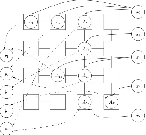
Fig. 2. A simple mapping of a parallel SMVM operations in NoC
architecture.
For example, a simple direct mapping of Eq. (2) on this NoC platform is shown in Fig. 2. First of all, the vector componentsxj and nonzero matrix elementsAijwill be
dis-tributed according to the column indexj through the mesh network; i.e. vectorx1arrives in the PEs withA11,A21 and
A51elements (4, 6, 7), vectorx2arrives in the PE withA32
element (1), vectorx3arrives in the PEs withA13,A23
ele-ments (8, 3) and vectorx4arrives in the PE withA44element
(5), vectorx5 arrives in the PE withA55 element (5) in the
network, respectively. Second, each local PE will perform the multiply operationsAij·xjin parallel. After the multipli-cations, the results of the productsb(j )i =Aij·xj are routed to other PEs (as indicated by the dashed lines). Finally, the
bi(j )are added up according to the row indexiof matrixAij to obtainbi.
Mul
A
ddr
Vec_Reg Mul_FIFO
Acc_FIFO
PE_Ar
b
ite
r
MUX
Sum_Reg Controller
FIFO DataIn
DataOut
PE
0
1
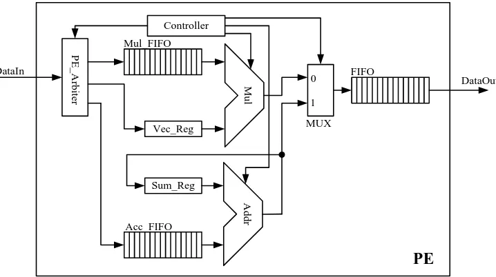
Fig. 3. Schematic view of the PE.
3 Implementation
Our basic idea described in Sect. 2.3 is now implemented on the architecture of Fig. 1. In Fig. 1, the vector compo-nents and nonzero matrix elements will distribute from the data entry points at the left side of the platform to each PE through the mesh network. The transmissions are done by packet-switched networks overlaid on top of commodity FP-GAs. Finally, the PEs will add up all row index products and send it to the result port in packet style at the right side of the platform. Since the routing scheme for sending data packets between PEs negotiates dynamically at run time, this promises no additional memory for storing schedules and no further off-line setup.
3.1 Processor element
Fig. 3 shows the schematic view of a PE, including one float-ing point adder, one floatfloat-ing point multiplier, controllers and FIFOs. The input packets will be first decomposed by the “PE Arbiter” then forward to the ACC/MUL FIFOs or the Vector Register. After that, PE will perform a multiplica-tions and the accumulation in IEEE 754 single float point precision. In the current configuration, each PE can hold at most 32 nonzero matrix elements in the Mul FIFO, one vec-tor component, 32 accumulation matrix elements in the ACC FIFO and 32 packets in the output FIFO.
3.2 Switch structure
A basic switch component for the local PE to communicate its neighboring PEs consists of a set of input/output ports, a crossbar network, four input FIFO buffers and a controller circuit as shown in Fig. 4. The switch we used has five data
Fig. 4. Detailed switch interconnections of a PE for its neighboring
communication.
input ports and five data output ports. These ports are named North, East, West, South and Local respectively. In order to be able to prevent the deadlock hazard, Round-Robin strat-egy is used when several packets arrive at a switch simulta-neously.
3.3 Routing algorithm
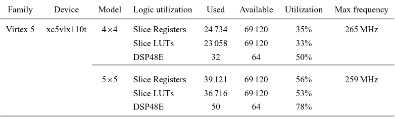
Table 1. Synthesis Results for SMVM Calculator based on NoC Architecture.
Family Device Model Logic utilization Used Available Utilization Max frequency
Virtex 5 xc5vlx110t 4×4 Slice Registers 24 734 69 120 35% 265 MHz
Slice LUTs 23 058 69 120 33%
DSP48E 32 64 50%
5×5 Slice Registers 39 121 69 120 56% 259 MHz
Slice LUTs 36 716 69 120 53%
DSP48E 50 64 78%
information of this packet and arbitrate the direction, then transmit to next switch in the network. Each packet is first routed along X coordinate and then along Y coordinate until this packet reaches the destination.
4 Experimental result
We have first modeled our proposed architecture in Verilog HDL and synthesized it with Xilinx ISE 10.1 SP3. Later, we verified our implementation on the Xilinx XUPV505 (XC5VLX110T). The synthesized resource utilization re-ports are shown in Table 1. When the network size is 4×4, it can achieve a peak performance 8.29 GFLOPS in theory. Each PE can hold at most(32×3+2)=98 packets and in to-tal(4×4×98)+(24×2×32)=3104 packets of the SMVM-NoC architecture. A simple testing with a 16×16 dense ma-trix vector multiplication in a 4×4 network has been veri-fied. Note that so far we have only tested the dense ma-trix multiplication. Although we have only experimented on dense matrix multiplication, the only limiting is the number of the nonzero elements in the sparse matrix. Therefore, no matter these nonzero elements are from a sparse matrix or a dense matrix the NoC network does not treat them dif-ferently. On the other hand, since we used the Xilinx Mi-croBlaze in FPGA to inject the packets, it is effortless to ex-tend the current architecture to calculate the sparse matrix by modifying the testing program later.
5 Conclusions
In this paper, we presented an idea of the SMVM-NoC archi-tecture. In this architecture, we have tested a 16×16 dense matrix vector multiplication in IEEE 754 single float point precision in FPGA. Note that a sparse matrix with 16·16=256 nonzero elements requires the same resources. The advan-tages of introducing the NoC structure into SMVM computa-tion are given by high resource utilizacomputa-tion, flexibility and the ability to communicate among heterogeneous systems. Since the NoC structure can receive data from and forwards results
to different entries simultaneously, this makes it able to deal with very large sparse matrix and disrespect the structure of the sparse matrix. The synthesis results showed that the ad-vanced FPGA with the chip-internal NoC network provides a solution for sparse matrix computation to further acceler-ate many numerically problems in hardware, such as solving linear equation (CG method), FEM problem and so on.
Future work will extend this architecture to be able to pro-cess sparse matrices of arbitrary structure. A detailed per-formance analysis of different routing algorithms, network topologies and switch architecture will be done. At the end, we will compare it with other sparse matrix computation architectures in different design criteria (area, timing and power).
References
Benini, L. and Micheli, G. D.: Networks on Chips: A New SoC Paradigm, Computer, 35, 70–78, 2002.
Bertozzi, D. and Benini, L.: Xpipes: a network-on-chip architecture for gigascale systems-on-chip, Circuits and Systems Magazine, IEEE, 4, 18–31, 2004.
deLorimier, M. and DeHon, A.: Floating-point sparse matrix-vector multiply for FPGAs, in: FPGA ’05: Proceedings of the 2005 ACM/SIGDA 13th international symposium on Field-programmable gate arrays, 75–85, ACM, New York, NY, USA, doi:http://doi.acm.org/10.1145/1046192.1046203, 2005. Elkurdi, Y., Fern´andez, D., Souleimanov, E., Giannacopoulos, D.,
and Gross, W. J.: FPGA architecture and implementation of sparse matrix-vector multiplication for the finite element method, Computer Physics Communications, 178, 558–570, 2008. Gregg, D., Mc Sweeney, C., McElroy, C., Connor, F., McGettrick,
S., Moloney, D. and Geraghty, D.: FPGA Based Sparse Matrix Vector Multiplication using Commodity DRAM Memory, in: In-ternational Conference on Field Programmable Logic and Appli-cations, 786–791, 2007.
Golub, G. H. and Van Loan, C. F.: Matrix computations (3rd ed.), Johns Hopkins University Press, Baltimore, MD, USA, http:// portal.acm.org/citation.cfm?id=248979, 1996.
1988.197034, 1988.
Hemani, A., Jantsch, A., Kumar, S., Postula, A., Oeberg, J., Mill-berg, M., and Lindquist, D.: Network on a Chip: An Architecture for Billion Transistor Era, in: Proceedings of IEEE NorChip, 24– 31, New York, 2000.
Kapre, N. and DeHon, A.: Optimistic Parallelization of Floating-Point Accumulation, in: ARITH ’07: Proceedings of the 18th IEEE Symposium on Computer Arithmetic, pp. 205–216, IEEE Computer Society, Washington, DC, USA, 2007.
McGettrick, S., Geraghty, D., and McElroy, C.: An FPGA architec-ture for the Pagerank eigenvector problem, Field Programmable Logic and Applications, 2008. FPL 2008. International Confer-ence on, 523–526, 2008.
Morris, G. R. and Prasanna, V. K.: Sparse Matrix Computations on Reconfigurable Hardware, Computer, 40, 58–64, doi:http://doi. ieeecomputersociety.org/10.1109/MC.2007.103, 2007.
Sun, J., Peterson, G., and Storaasli, O.: Sparse Matrix-Vector Mul-tiplication Design on FPGAs, in: FCCM ’07: Proceedings of the 15th Annual IEEE Symposium on Field-Programmable Custom Computing Machines, 349–352, 2007.
Williams, S., Oliker, L., Vuduc, R., Shalf, J., Yelick, K., and Dem-mel, J.: Optimization of sparse matrix-vector multiplication on emerging multicore platforms, in: SC ’07: Proceedings of the 2007 ACM/IEEE conference on Supercomputing, 1–12, ACM, New York, NY, USA, doi:http://doi.acm.org/10.1145/1362622. 1362674, 2007.
Wolf, W.: The future of multiprocessor systems-on-chips, Annual ACM IEEE Design Automation Conference, 681–685, 2004.
Zhuo, L. and Prasanna, V. K.: Sparse Matrix-Vector
multi-plication on FPGAs, in: FPGA ’05: Proceedings of the