Copyright © 2013 IJECCE, All right reserved
Digital Signal Controller Based Digital Control of
Brushless DC Motor
Anjana Elizabeth Thomas, Salim Paul
Abstract — This paper presents the digital control of a brushless dc (BLDC) motor using TMS320F2812 DSP controller and an EPROM. The real-time control of electrical motors is an application area that is not usually the domain of Digital Signal Processors. The TMS320F2812 has got dedicated modules for digital motor control. Control algorithms used for the control has been in TMS320F2812 DSP controller. The output of the driver is 6 independent PWM pulses that have to be given to the corresponding gates of the six MOSFETs power switches used in the three-phase bridge driving circuit whose output is given to the stator of the Brushless DC Motor. The commutation technique used in this work is the trapezoidal commutation owing to its excellent speed and current control and it has been implemented using an EPROM.
Keywords — BLDC Motor, Commutation, Digital Signal Controller, EPROM, Pulse Width Modulation.
I. I
NTRODUCTIONBLDC motors are nowadays becoming more and more popular in various applications including aerospace due to their superior controllability and performance such as high efficiency due to reduced losses, compactness, long operating life, high dynamic response, noiseless operation, low maintenance, lower switching loss, low rotor inertia and better speed versus torque characteristics[1],[2]. In this work, a digital controller for BLDC motor is developed which uses minimum number of components employing a DSP controller (TMS320F2812) by Texas Instruments (TI).
Traditionally, inexpensive analog components were used for the design purposes of motor drives. The weaknesses of the analog systems are their susceptibility to temperature variations, component ageing and difficulty in upgrading the systems. It also has the disadvantage of complex circuits and lower reliability. In the digital control systems, the upgrades can be easily accomplished by software. This improves the degree of efficiency, resolution control and allows the implementation of more advanced control schemes. It is a natural progression to use the internal hardware computing units of a DSP to transfer the calculation from a standard microprocessor to a DSP. Reduced manufacturing and maintenance costs results in less loss of power, lower vibration, and longer life. The TMS320F2812 DSP controllers are designed to meet the needs of control-based applications. At 20 million instructions per second (MIPS), DSP controllers offer significant performance over traditional 16-bit microcontrollers and microprocessors[3],[4].
The BLDC Motor is a rotating electric motor consisting of stator armature windings and rotor permanent magnets whereas in a conventional brushed DC motor the stator is made up of permanent magnets and rotor consists of
armature windings. The conventional DC motor commutates itself with the use of a mechanical commutator whereas brushless DC motor needs electronic commutation for the direction control of current through the windings. In the DC commutator motor, the current polarity is reversed by the commutator and the brushes, but in the brushless DC motor, the polarity reversal is performed by semiconductor switches which are to be switched in synchronization with the rotor position. The commutator is also a limiting factor in the maximal speed of the DC motor and hence besides the higher reliability, the missing commutator brings another advantage. Therefore the BLDC motor can be employed in applications requiring higher speed.
The three - phase BLDC motor drive consists of a power stage with a three-phase full-bridge scheme as shown in Figure 1 and a controller that should provide three - phase PWM signals to drive the MOSFET gates, based on three Hall-effect sensors or an encoder or a resolver for the rotor position feedback. For proper commutation and for motor rotation, the rotor position information is very crucial. Only with the help of rotor position information, the electronic switches in the bridge will be switched ON and OFF to ensure proper direction of current flow into respective coils. Energizing the appropriate phase coils based on the rotor position is known as commutation logic.
The three commutation techniques that are generally used are the six – step trapezoidal, sinusoidal and Field Orientation Control (FOC), out of which we have chosen the trapezoidal commutation technique which is also called block commutation where only two of the three phases will be conducting at any given point of time. The algorithm complexity is less for trapezoidal commutation and it is easy to implement the control aspects of it. Also, the speed and current control of the BLDC motor using this commutation technique is excellent. The other two commutation techniques are highly expensive and are also relatively complex [5]. Hall Effect sensors [Hall2, Hall1, Hall0] are used in general as position sensors for trapezoidal commutation.
Copyright © 2013 IJECCE, All right reserved second section shows the block diagram which describes
how the control is achieved. The third section gives a brief description of the TMS320F2812 and its for the control. The fourth section shows the flowchart for software implementation and the last section shows the results obtained.
Fig.1. Three Phase Full Bridge Driving Circuit
II. B
LOCKD
IAGRAMThe block diagram for the control of brushless DC motor is as shown in figure 2. It consists of current command, feedback, PWM generation and commutation logic circuit, optocoupler, power amplifier gate driver, BLDC motor and sensors.
Here, Vcomrepresents the voltage corresponding to the
current that should flow through the phase of the BLDC motor. A shunt resistance is used to sense the actual current entering into the motor. The voltage corresponding to the phase of the motor is given as feedback. The current sensing signal and the voltage command are the inputs to the DSP that are given to the ADC module of the processor for further processing. The ADC module accepts input voltage only in the range 0-3V. So, an opamp is used to scale the inputs to the ADC to this range.
Fig.2. Block Diagram for the current control of the BLDC Motor
According to the input command, feedback and control algorithm, the PWM pulses for each phase is generated by the DSP. These PWM pulses are then given to the optocoupler followed by the MOSFET power amplifier gate driver. The output of the DSP are 6 independent PWM pulses that have to be given to the corresponding gate of the six MOSFETs power switches used in the three-phase full bridge circuit whose output is given to the stator of the BLDC motor. The duty cycle of the PWM signals depends on the error in the current through the coils. The system is designed in such a way as to generate
a 60% duty cycle PWM signal if there is no error. If the error is positive maximum, a higher duty cycle PWM signal is generated and if the error is negative minimum, a lower duty cycle PWM signal is generated.
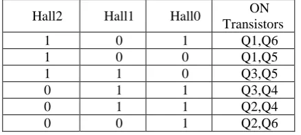
The motor consists of 3 Hall position sensors separated from each other by 120 degrees which means the signals outputted by the three sensors differ from each other by 120 degrees. The Hall sensors are used to distinguish which pole of the rotor permanent magnet is in which position, and turn on or off the appropriate coils accordingly so as to facilitate the appropriate current flow through the coils. The commutation technique used here, the trapezoidal commutation is a six – step commutation scheme in which current flows through two of the three coils of the motor at the same time. Commutation provides the creation of a rotation field. It is necessary to keep the angle between stator and rotor flux close to 90° for a BLDC motor to operate properly. Six-step control creates a total of six possible stator flux vectors. The stator flux vector must be changed at a certain rotor position. The Hall sensors generate three signals that also comprise six states. The Hall sensors generate three signals that also comprise six states and the commutation logic has been implemented in an EPROM as shown in the table1.
Table I. Hall Sensor Output and Current Flow
Hall2 Hall1 Hall0 ON
Transistors
1 0 1 Q1,Q6
1 0 0 Q1,Q5
1 1 0 Q3,Q5
0 1 1 Q3,Q4
0 1 1 Q2,Q4
0 0 1 Q2,Q6
Six PWM signals, generated by the DSP controller, are inputted to an optocoupler 6N134. The function of the optocoupler is to avoid high voltage or current signals in the main circuit disturbing the low voltage or current signals in the control system. The optocoupler isolates them from each other, which would also improve the security of the system. The output of the optocoupler is the input to the MOSFET driving circuit which outputs amplified PWM signals that are given to the gates of the MOSFETs. The power amplifier gate driver used is the IRF2110. The MOSFETs require high voltage signals and this is the reason why the MOSFET driving circuit is used. The commutation instants for the power inverter switches are determined by detecting edges from signals received from hall sensors. The commutation logic has been implemented through an EPROM.
Copyright © 2013 IJECCE, All right reserved
III. TMS320F2812
The TMS320F2812 is a new generation controller with main frequency of 150MHz.The speed and features of this DSP make it an excellent choice for the digital control of motors. The TMS320F2812 belongs to C2000 series of DSPs of the Texas Instruments which mainly focuses on industrial purposes. It has a powerful data processing capability and high speeds. The C2000 series DSP integrates the best features of DSP and microcontroller, and the F2812 is one of the most cost - effective DSP chip. It has an efficient math ability in addition to which, it also has a relatively perfect event management capabilities and embedded control functions, therefore it is widely used in industrial control, especially in high-volume data processing measurement and control applications with high demanding of processing speed and accuracy such as in aerospace.
The system based on the TMS320F2812 development platform, which contains a high-performance 32-bit DSP core can afford the maximum frequency of 150MHz [6]. TMS320F2812 have two integrated event managers (EVA, EVB), 12-Bit 16 channel ADC and many other functional modules. The Event Manager module and the ADC module are the two important modules of this DSC that are used for the work described in this paper.
The event-manager (EV) modules provide a broad range of functions and features that are particularly useful in motion control and motor control applications. The two EV modules, EVA and EVB, are identical peripherals, intended for multi-axis/motion-control applications. Each EV is capable of generating eight PWM signals: three independent pairs (six outputs) by the three full compare units with programmable deadbands, and two independent PWMs by the GP-timer compares [7].
TheADC module is a 12-bit pipelined analog-to-digital converter (ADC) which has 16 channels, configurable as two independent 8-channel modules to service event managers A and B. The two independent 8-channel modules can be cascaded to form a 16 channel module. The ADC module accepts input voltage from 0 to 3V. The fast conversion time runs at 25 MHz, ADC clock, or 12.5 MSPS. There are sixteen result registers (individually addressable) to store conversion values. The ADC can be started using a S/W − softwareimmediate start signal, or EVA − Event manager A (multiple event sources within EVA), or EVB− Event manager B (multiple event sources within EVB) or using an external pin [8]. Thus, the event manager unit and the ADC module of the TMS320F2812 processor enables easier and better implementation of digital motor control.
In order to design the most effective DSP system, code must be carefully optimized to make most of the available resources from the controller. Here assembly language programming is implemented which provides fastest execution and most compact form of algorithm. The assembler in the host computer translates the assembly program into object code that can be downloaded into the controllers program memory for execution. Software development tools are provided by the manufacturers of
DSP controllers in developing efficient code for the controllers. Code composer studio from Texas Instruments is an integrated development environment that incorporates the C compiler, assembler, linker, simulator, debugger etc., with additional features such as graphical display for developing DSP software.
IV. F
LOWCHART FOR THEC
ONTROL ANDS
OFTWAREI
MPLEMENTATIONThe flow chart of the program developed for the control is shown in figure 3.
Fig.3. Flowchart for the control
Copyright © 2013 IJECCE, All right reserved developed in the Code Composer Studio v3.1 and then
compiled and written into the controller.
The software is programmed as follows. First, we initialize the DSP and set up the ADC module to read the command and feedback signals. The error in the command and feedback is computed and PWM signals are generated accordingly. After updating the duty cycle, the PWM signals are given to the appropriate MOSFETs by reading the commutation logic programmed in the EPROM as shown in table1. The program has been written in Assembly language and C programming. C code is generally easier to read but assembly can be faster and more efficient if written well. Therefore, we prefer to use C whenever possible. However, in some certain circumstances (situations which are repeated a lot, time-critical code, etc) it may be necessary to put in some extra effort to save a few cycles. In such cases, we use assembly language programming.
V. R
ESULTSO
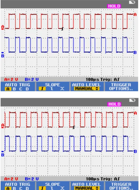
BTAINEDThe results include the gating pulses (PWM signals) from the DSP, the optocoupler, pulses at the gates of the six MOSFETs and currents through each phase of the motor. Figure 4 shows the six gating pulses with duty cycle 60% from the DSP which are inputs to the optocoupler. The gating pulses are generated from the DSP depending upon the error in the current through the motor. It has been programmed to generate a 90% duty cycle PWM if the error is positive, 30% duty cycle PWM if the error is negative and 60% duty cycle PWM if error is zero.Figure 5a, 5b and 5c shows the corresponding optocoupler outputs. Each optocoupler takes two PWMS as input and generates corresponding output PWMs, one for upper transistor and the other for lower transistor. Similar to the optocoupler, each power amplifier gate driver IC takes in two PWMs as input and generates amplified PWM signals respectively, one for upper transistor and the other for lower transistor. Figure 6a shows power amplifier gate driver output for upper transistors and 6b shows power amplifier gate driver output for lower transistors. Similar results are obtained for the remaining upper and lower transistors respectively. Figure 7a, 7b and 7c shows the current through the phases of the motor. The motor generated a current of 1.8A peak to peak which is in accordance with the specifications.
Fig.4. Gating pulses from the DSP
Copyright © 2013 IJECCE, All right reserved Fig.5b. Optocoupler2 outputs
Fig.5c. Optocoupler3 outputs
Fig.6a. Gate driver output of upper transistor
Fig.6b. Gate driver output of lower transistor
Fig.7a. Current through phase A
Copyright © 2013 IJECCE, All right reserved Fig.7c. Current through phase C
VI. C
ONCLUSIONThe digital control of brushless DC motor has been successfully implemented using the TMS320F2812 and EPROM. The ADC module and the event manager module of the processor aids the processing of the input signals and generation of PWMs. These PWM signals turns the power MOSFETs ON and OFF according to the commutation logic programmed in the EPROM.
A
CKNOWLEDGMENTThe authors would also like to express their sincere gratitude to the faculty members of the Department of Electronics and Communication Engineering, SCT College of Engineering, Trivandrum for the support and encouragement they have extended in the course of this project.
R
EFERENCES[1] G. Madhusudhana Rao et al. “Speed Control of BLDC Motor Using DSP” International Journal of Engineering Science and Technology, Vol. 2(3), 2010.
[2] Bhim Singh,B P Singh,(Ms) K Jain “Implementation of DSP
Based Digital Speed Controller for Permanent Magnet Brushless
dc Motor”IE(I) Journal-EL, Vol 84, June 2003.
[3] Petru dobra et al. “Digital control applications using TI digital signal processors”WSEAS Transactions on systems and control, Issue 6,volume3,June2008.
[4] G Prasad, Venkateswara Reddy M, Dr. P V N Prasad, Dr. G
Tulasi Ram Das, “Control of Brushless DC motor with DSP controller using Matlab” International Journal of Engineering Research and Applications (IJERA) Vol. 2, Issue 3, May-Jun 2012, pp.2120-2125.
[5] G.Liu ,W.G Dunford, “Comparison of sinusoidal excitation and trapezoidal excitation”Fourth International Conference on Power Electronics & Variable Speed Drives,vol.17 , pp.446-450. [6] “TMS320F2812 Digital signal Processors Data manual, Texas
Instruments, Literature Number :SPRS174R, April 2001 [7] “TMS320C281x Event manager Reference Guide, Texas
Instruments, Literature Number:SPRU065e
[8] “TMS320x281xAnalog-to-Digital Converter(ADC) Reference
Guide”,Texas Instuments, Literature Number: SPRU060D, June 2002
[9] “Code composer studio Getting started guide”, Texas Instruments, Literature Number:SPRU509,May 2001.
A
UTHORSP
ROFILEAnjana Elizabeth Thomas
is currently pursuing her M.Tech in Signal Processing at SCT College of Engineering, Trivandrum, Kerala. She graduated in Applied Electronics and Instrumentation in the year 2010 from LBS Institute of Technology for Women, Trivandrum, Kerala. She has presented her paper in the National Conference on Advanced Computational Intelligence and Communication Technologies. Her research area includes digital signal processors and control electronics.
Email: [email protected]