Application of a Chaotic Synchronization System to Secure Communication
Her-Terng Yau
1, Yu-Chi Pu
2, Simon Cimin Li
3 1Department of Electrical Engineering, National Chin-Yi University of Technology, Taichung 411, Taiwan
e-mail: [email protected] 2
Department of Electrical Engineering, Far-East University, Tainan 744, Taiwan 3
Department of Electrical Engineering, National University of Tainan, Tainan 700, Taiwan
http://dx.doi.org/10.5755/j01.itc.41.3.1137
Abstract. This work describes a novel scheme that applies a Sprott master/slave chaotic synchronization system to secure transmission. A sliding plane is chosen to design a sliding mode controller to ensure robustness. In the presence of an external disturbance and system uncertainty, the slave chaotic circuit system is then synchronized with the master. The Lyapunov theorem verifies that the proposed controller is stable and robust. Simulation results indicate that the synchronization error state asymptotically converges to the origin of the phase plane, implying that the master/slave chaotic system synchronization is achieved while the sliding mode controller is in operation. While consisting of operational amplifiers, resistors, capacitors and diodes, the chaotic circuit system together with a sliding mode controller is subsequently implemented to validate the system synchronization. Finally, the chaotic system combined with cryptography is embedded into a chaotic synchronization cryptosystem to resolve secure communications-related problems.
Keywords: Chaotic synchronization; Sliding mode controller; Sprott system; Lyapunov theorem; secure
communication.
1. Introduction
Based on atmospheric simulation, Lorenz pioneered the chaos theory, a seemingly disordered
phenomenon [1]. Until the general theory of
Feigenbaum in 1978, chaos received scarce scientific attention. As a complex and aperiodic nonlinear system, the time response of chaotic system is extremely sensitive to initial conditions. Otherwise, it also has a wide range of the Fourier spectrum and is characterized by the fractal geometry on the phase plane. That is, even with an identical system, the system response varies significantly with various initial conditions, a phenomenon referred to as the butterfly effect. Having been extensively studied, chaos can be found in a diverse array of research fields, including electrical engineering, electronics, communications, biology, mathematics, physics, chemistry, and economics. The Lorenz system has been applied to atmospheric science, the Duffing system to mechanics, the Rössler system to chemical engineering, and Chua's circuit [2-3] to circuitry.
Chaotic synchronization has been extensively studied in recent decades [4-8]. While normally consisting of a master system, slave system, and synchronization controller, this system transmits a
state signal to the controller, followed by processing and subsequent application to the slave system, as an alternative approach to locus synchronization between both systems. The concept of chaotic synchronization has not, until recently, been applied to the communications field [9-16], in which the signal intended for delivering a chaotic signal in the transmitter is modulated and the received signal in the receiver is then demodulated into the original one. However, transmission security is of priority concern [17], largely owing to that an individual familiar with the chaotic theory can easily intercept information during transmission. To resolve such security concerns, a scheme [18-21] based on the original chaotic system in combination with encryption skills utilizes the chaotic system to encrypt the transmitted data by an encryption function, followed by modulation by a chaotic signal to increase the complexity and security of such transmitted signals.
function is used to replace the discontinuous sign function in the final design process step, can eliminate chattering in the control input to ensure feasibility for an actual physical system. However, to our knowledge, no previously developed scheme can obtain such a robust continuous controller for chaos synchronization control in a secure communications system, necessitating the development of a sliding mode control scheme. Therefore, based on a sliding mode controller [22], this work addresses the synchronization issue of a chaotic system, while devising a sliding mode control criterion. While implemented with electronic components, system synchronization is validated using the chaotic system and the controller. Finally, by using LabView, the chaotic synchronization system, integrated with cryptography, is applied to secure communication i.e. the encryption and decryption of audio and image signals.
2. System descriptions
This work focuses on a Sprott chaotic system, where the governing equation is expressed in a differential form [23-24] as
x G x x ax i
, (1)
where Gi
x denotes any of the underlying functions
x x sign
x Gx sign x
x G
x x
G x x G
2 2 . 1
5 . 4 2 . 1
5 . 0 0 , max 6
2
4 3 2 1
,
where max
refers to a maximum value function, aswell as sign
the sign function. While consideringthe circuit implementation, the system state variables are assumed to be
x
1
x
,x
2
x
,x3 x. A stateequation is subsequently derived as
. a 32 3
3 2
2 1
x G x x x
x x
x x
i
(2)
Consider a situation in which Gi
x G4
x1
11 2
2 .
1 x sign x
and a=0.6 are selectedsince it is
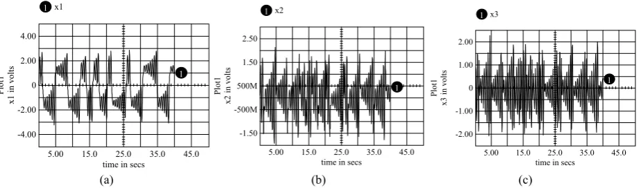
easily implemented by electronic circuits and chaotic motion has been proven to exist [23]. The dynamic response is then simulated with Matlab and IsSpice software packages as shown in Figs. 1 and 2. Figure 3 summarizes the implementation results of the electronic circuits indicating that the Sprott system has complex dynamics.
(a) (b) (c)
Figure 1. Given initial condition
x1
0 ,x2 0 ,x3 0
0.1,0.1 ,0.1
, the simulated time responseby MATLAB to (a) x1, (b) x2, (c) x3
(a) (b) (c)
Figure 2. Given initial condition
x1
0, x20, x30
0.1 ,0. 1 ,0.1
, the simulated time responseby IsSpice to (a) x1, (b) x2, (c) x3
0 5 10 15 20 25 30 35 40
-4 -3 -2 -1 0 1 2 3 4
Time(sec)
x1
x1
0 5 10 15 20 25 30 35 40
-3 -2 -1 0 1 2 3
Time(sec)
x2
x2
0 5 10 15 20 25 30 35 40
-2.5 -2 -1.5 -1 -0.5 0 0.5 1 1.5 2 2.5
Time(sec)
x3
x3
1 x1
5.00 15.0 25.0 35.0 45.0
time in secs -4.00
-2.00 0 2.00 4.00
x1
in volts
Plot1
1
1 x2
5.00 15.0 25.0 35.0 45.0
time in secs -1.50
-500M 500M 1.50 2.50
x2
in volts
Pl
ot
1
1
1 x3
5.00 15.0 25.0 35.0 45.0
time in secs -2.00
-1.00 0 1.00 2.00
x3
in volts
Plot1
(a)
(b)
(c)
(d)
(e)
(f)
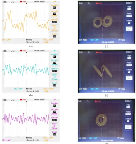
Figure 3. Circuit hardware responses to (a) x1, (b) x2, (c) x3, and phase plane of (d) x1 versus x2,
(e) x1versus x3, (f) x2versus x3
The dynamic equations of both the master and slave chaotic systems in the Sprott circuit addressed here, are expressed as
Master:
,1 3, 2
, 1 , 3
, 3 , 2 ,
2 , 1 ,
sign 2 0.6 .2
1 m m m m
m m m
m m
x x
x x x
x x
x x
(3)
Slave:
t u dx x
x x x
x x
x x
s s
s s s
s s
s s
sign 2 0.6
-Δ
1.2 ,1 ,2 ,3 ,1
3 ,
3 , 2 ,
2 , 1 ,
(4)
where Δ denotes system uncertainty, d
t externaldisturbance, and
u
the controller added. The controltarget is specified as
0lim
xs t xm t
t
(5)
indicating that the slave synchronizes with the master.
3. Robust synchronization controller design
3 , 3 , 3 2 , 2 , 2 1 , 1 , 1 m s m s m s x x e x x e x x e (6)
From Eq. (6), it then follows that
x x d
t u sign x sign e e e u t d x x sign x sign x x x x x x x sign x x x u t d x sign x x x e e e e e s m s s m s m s m s m s m m m m s s s s 1 , 1 , 1 , 3 2 1 1 , 1 , 1 , 3 , 3 , 2 , 2 , 1 , 1 , 1 , 3 , 2 , 1 , 1 , 3 , 2 , 1 , 3 3 2 2 1 Δ 2 2 6 . 0 2 . 1 Δ 2 2 6 . 0 2 . 1 2 0.6 .2 1 2 0.6 Δ 1.2 . (7)First, a sliding plane is chosen as
3 3 2 2 1
1e c e c e
c
s . (8)
In the sliding mode,
s
0
holds true, and theequivalent controller is expressed as
3 3 1 , 3 1 , 3 1 , 3 3 2 2 3 1 1 3 3 3 1 , 3 1 , 3 1 , 3 3 2 2 3 1 1 3 1 , 1 , 1 , 3 2 1 3 3 2 2 1 3 3 2 2 1 1 / Δ 2 2 6 . 0 2 . 1 0 Δ 2 2 6 . 0 2 . 1 0 Δ 2 2 6 . 0 2 . 1 0 c t d c x c x sign c x sign c e c e c c e c u u c t d c x c x sign c x sign c e c e c c e c u t d x x sign x sign e e e c e c e c e c e c e c s s m s eq eq s m s eq s m s (9)For simplicity, by allowing c31, Eq. (9) is
rewritten as
t d x x sign x sign e c e c e u s m s eq 1 , 1 , 1 , 3 2 2 1 1 Δ 2 2 6 . 0 1 2 . 1 (10)Subsequently, the approaching law is designed as
s sign Wusw , where the sign function sign
isdefined as 0 , 1 0 , 1 s s s sign .
With a lack of knowledge concerning uncertainty
Δ and external disturbance d
t , the systemimplemented in practice can be expressed as
s sign W x sign x sign e c e c e u u u m s sw eq 2 2 6 . 0 1 2 . 1 1 , 1 , 3 2 2 11 (11)
Remark: The controller in (11) demonstrates
discontinuous control laws and chattering occurs as well. From reference [25], chattering is eliminated by modified the controller as
s s W x sign x sign e c e c e u u u m s sw eq 2 2 6 . 0 1 2 . 1 1 , 1 , 3 2 2 11 (12)
where
denotes a sufficiently small design constant.Here, constant
is selected as 0.05. Therefore, thecontrollers can be implemented in a real world system. Next, the stability and robustness of the controller of Eq. (11) are proven in the following.
Via the Lyapunov theorem, the system stability is verified as
22 1
s t
V .
The first order time derivative is written as
x dt W signs
s s sign W x sign x sign e c e c e t d x x sign x sign e c e c e s u t d x x sign x sign e e e c e c e c s e c e c e c s s s V s m s s m s s m s 1 , 1 , 1 , 3 2 2 1 1 1 , 1 , 1 , 3 2 2 1 1 1 , 1 , 1 , 3 2 1 3 3 2 2 1 3 3 2 2 1 1 Δ 2 2 6 . 0 1 2 . 1 Δ 2 2 6 . 0 1 2 . 1 Δ 2 2 6 . 0 2 . 1 . (13)The physical meanings of external disturbances
and system uncertainties d
t and Δdenote modelsof the unstructured system models and uncorrected system parameters of Sprott systems. Otherwise, the system states of the Sprott system are also attracted to a bounded attractor. Therefore, they can be assumed to
be bounded that is xs,1
, Δ , d
t .Then Eq. (13) can be rewritten as
W
s s W s s W t d x s V s
Δ ,1
. (14)
If
W , (15)
then V 0 ensures a stable system. By using Matlab
software, feasibility of the controller in Eq. (12) is verified, with the parametersc110, c210, W0.9,
while those in Eq. (4) are Δ 0.1sin
t ,
t
taccording to Fig. 4, xs,14.33, a substitution of
which into Eq. (14) yields W0.533. To maintain a
stable system, a choice of W0.9 is made accordingly.
Figure 4. Time response to xm,1,xs,1. The control is active at t=25 sec
4. Applications in secure communication
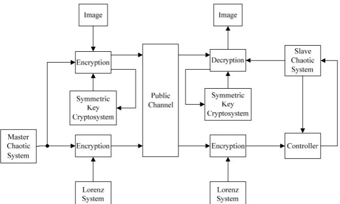
This section describes the application of a cryptosystem, constructed based on the Sprott chaotic synchronization system integrated with cryptography
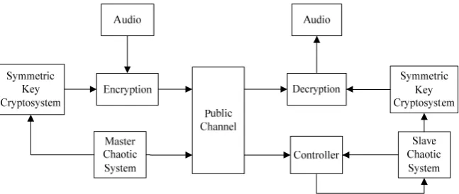
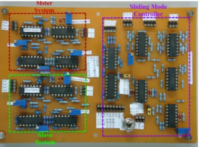
to secure communications. The transmission link is established via the Internet and National Instruments LabView, with the information encrypted and decrypted in the transmitter and the receiver, respectively, by computers. The audio signal is transmitted as follows. First, the initial conditions of the system and the sampling amount are determined. An identical number of keys are then generated, with which the audio signal is mixed accordingly. Figures 5 to 7 display the audio processing system, as well as summarize the experimental results. The image counterpart is described as follows. The encryption process is divided into two phases. The first one is the image itself, with both the symmetric key cryptosystem (SKC) and the master/slave system as the key, through which the image signal is encoded despite the same set of initial values. The initial values subsequently vary with the master/slave system status. The second one is the encryption of the master/slave system signal, with a Lorenz system as the key, as a means of removing the interception likelihood during data transmission. Figure 8 illustrates the image encryption/decryption system, where the Lorenz system is of invariant initial conditions; meanwhile, the master chaotic system randomly generates the initial conditions. Figures 9 to 11 summarize the experimental results. An entity photo of a Sprott master/slave system and a sliding mode controller are shown in Fig. 12.
Figure 5. An audio encryption/decryption flow in a chaotic synchronization cryptosystem
(a)
0 5 10 15 20 25 30 35 40
-5 -4 -3 -2 -1 0 1 2 3 4 5
Time(sec)
、
xm
1
xs1
(b)
(c)
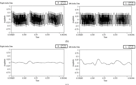
Figure 6. An audio signal zoomed in. (a) The original audio zoomed in; (b) An encrypted version of (a);
(c) A decrypted version of (b).
(a) The spectrum of the original right channel audio
(b) The spectrum of the encrypted right channel audio
(c) The spectrum of the decrypted right channel audio
(e) The spectrum of the encrypted left channel audio (f) The spectrum of the decrypted left channel audio
Figure 7. The Spectrum of the original and encrypted audio
Figure 8. Image encryption/decryption flow of a chaotic synchronization cryptosystem
(a) (b)
(a) (b)
Figure 10. The encrypted image of Lenna and its spectrum. (a) An encrypted image; (b) The spectrum of (a)
(a) (b)
Figure 11. The decrypted image of Lenna and its spectrum. (a) A decrypted image; (b) The spectrum of the decrypted image
Figure 12. An entity photo of a Sprott master/slave system
and a sliding mode controller
5. Conclusion
This work presents a novel robust controller scheme which operates in the sliding mode. The proposed scheme is also applied to a chaotic circuit system in order to derive a solution to the
synchronization problem. Based on MATLAB and IsSpice software, simulation results indicate that the adequately designed sliding mode controller is robust and stable. This study schematically depicts the circuit hardware, implemented with OP amplifiers and RC elements. Highly promising for communications-related applications, the encryption/decryption system of audio and image signals exhibits elevated security and confidentiality during data transmission.
References
[1] E. N. Lorenz. Deterministic non-periodic flow.
Journal of the Atmospheric Sciences, Vol. 20, 1963,
130–141. http://dx.doi.org/10.1175/1520-0469(1963)0 20<0130:DNF>2.0.CO;2.
[2] L. O. Chua, G. N. Lin. Canonical realization of
Chua’s circuit family. IEEE Transactions on Circuits
and Systems, Vol. 37, 1990, 885-902. http://dx.doi.or
g/10.1109/31.55064.
[3] A. I. Lerescu, N. Constandache, S. Oancea,
I. Grosu. Collection of master–slave synchronized
Vol. 22(3), 2004, 599–604. http://dx.doi.org/10.1016/j. chaos.2004.02.039.
[4] E. Ott, C. Grebogi, J. A. Yorke. Controlling Chaos.
Phys. Rev. Lett., Vol. 64, 1990, 1196-1199.
http://dx.doi.org/10.1103/PhysRevLett.64.1196.
[5] L. M. Pecora, T. L. Carroll. Synchronization in
chaotic systems. Phys Rev Lett Vol. 64, 1990, 821–824.
http://dx.doi.org/10.1103/PhysRevLett.64.821.
[6] S. Chen, J. Lü. Synchronization of an uncertain
unified chaotic system via adaptive control. Chaos,
Solitons and Fractals, Vol. 14,2002, 643-647.
http://dx.doi.org/10.1016/S0960-0779(02)00006-1.
[7] G. Wen, Q. G. Wang, C. Lin, X. Han, G. Li.
Synthesis for robust synchronization of chaotic systems under output feedback control with multiple random delays. Chaos , Solitons and Fractals, Vol. 29,
2006, 1142-1146. http://dx.doi.org/10.1016/j.chaos.200 5.08.078.
[8] H. Zhang, X. K. Ma, W. Z. Liu. Synchronization of chaotic systems with parametric uncertainty using active sliding mode control. Chaos , Solitons and
Fractals, Vol. 21,2004, 1249-1257. http://dx.doi.org/
10.1016/j.chaos.2003.12.073.
[9] T. Yang, L. O. Chua. Impulsivee stabilization for control and synchronization of chaotic systems: theory and application to secure communication. IEEE Transactions on Circuits and Systems I: Fundamental
Theory and Applications, Vol. 44(10), 1997, 976-988.
http://dx.doi.org/10.1109/81.633887.
[10] H. Dedieu, M. Ogorzalek. Signal coding and
compression based on chaos control techniques. IEEE International Symposium on Circuits and Systems, Vol. 2, 1991, 1191-1194.
[11] A. V. Oppenheim, G. W. Wornell, S. H. Isabelle,
K. M. Cuomo. Signal processing in the context of
chaotic signals. IEEE International Conference on
Acoustics, Speech, and Signal Processing, Vol. 4, 1992,
117-120.
[12] H. Dedieu, M. P. Kennedy, M. Hasler. Chaos shift
keying: modulation and demodulation of a chaotic carrier using self-synchronizing chua’s circuits. IEEE Transactions on Circuits and Systems II: Analog and
Digital Signal Processing, Vol. 40, 1993, 634-642.
http://dx.doi.org/10.1109/82.246164.
[13] N. J. Corron, D. W. Hahs. A new approach to
communications using chaotic signals. IEEE Transactions on Circuits and Systems I: Fundamental
Theory and Applications, Vol. 44, 1997, 373-382.
http://dx.doi.org/10.1109/81.572333.
[14] K. M. Short. Uumasking a modulated chaotic
communications scheme. International. Journal of
Bifurcation and Chaos, Vol. 6, 1996, 367-375.
http://dx.doi.org/10.1142/S0218127496000114. [15] D. R. Frey. Chaotic Digital Encoding:An Approach
to Secure Communication. IEEE Transactions on IEEE Trans. Circuits and Systems II: Analog and
Digital Signal Processing, Vol. 40, 1993, 660-666.
[16] T. L. Liao, S. H. Tsai. Adaptive synchronization of
chaotic systems and its application to secure communications. Chaos Solitons and & Fractals, Vol.
11(9), 2000, 1387-1396. http://dx.doi.org/10.1016/S 0960-0779(99)00051-X.
[17] T. Yang, L. B. Yang, C. M. Yang. Breaking chaotic
switching using generalized synchronization: Examples. IEEE Transactions on Circuits and Systems
I: Fundamental Theory and Applications, Vol. 45,
1998, 1062-1067. http://dx.doi.org/10.1109/81.728860. [18] T. Yang, C. W. Wu, L. O. Chua. Cryptography based
on chaotic systems. IEEE Transactions on Circuits and Systems I: Fundamental Theory and Applications, Vol.
44, 1997, 469-472. http://dx.doi.org/10.1109/81.572 346.
[19] G. Grassi, S. Mascolo. A system theory approach for
designing cryptosystems based on hyperchaos. IEEE Transactions on Circuits and Systems I: Fundamental
Theory and Applications, Vol. 46, 1999, 1135-1138.
http://dx.doi.org/10.1109/81.788815.
[20] T. Y. Chang, M. S. Hwang, W. P. Yang. An
improved multi-stage secret sharing scheme based on the factorization problem. Information Technology and
Control, 2011, Vol. 40(3), 246-251. http://dx.doi.org/1
0.5755/j01.itc.40.3.633.
[21] J. W. Hong, S. Y. Yoon, D. I. Park, M. J. Choi,
E. J. Yoon, K. Y. Yoo, Anew efficient key agreement
scheme for vsat satellite communications based on elliptic curve cryptosystem. Information Technology
and Control, 2011, Vol. 40(3), 252-259.
[22] A. G. AK, G. Cansever, A. Delibasi. Robot trajectory
tracking with adaptive RBFNN-based fuzzy sliding mode control. Information Technology and Control,
2011, Vol. 40(2), 151-156.
[23] J. C. Sprott. A new class of chaotic circuits. Phys Lett
A Vol. 266, 2000, 19–23. http://dx.doi.o
rg/10.1016/S0375-9601(00)00026-8.
[24] D. I. R. Almeida, J. Alvarez, J. G. Barajas. Robust
synchronization of Sprott circuits using sliding mode control. Chaos, Solitons and Fractals Vol. 30(1), 2006,
11-18. http://dx.doi.org/10.1016/j.chaos.2005.09.011. [25] J. E. Slotine, W. Li.Applied Nonlinear Control, New
Jersey, Prentice-Hall, 1991.