Volume 02, No. 4, April 2016
P
age
178
Experimental Analysis on the Effect of Condenser Diameter on the
Performance of a Simple Vapor Compression Refrigeration System
Debabrata Panda*, Irfan Ahmed**, Sumit Gupta***
& Shivam Agrawal****
Department of Mechanical Engineering, Gandhi institute Of Engineering And Technology, Gunupur, India.
ABSTRACT:
The study of the condenser diameter in the simple vapour compression refrigeration system is necessary in order to understand the parameters which can enhance the overall performance of
the system. The experimental study was done on the condenser tubes of ¼ inch, 3/8th inch and
5/16 inch & each test section was studied with two distinct configurations i.e. free and forced convection. The effect of the configuration and the condenser tube diameter on the overall performance of the system was studied. The findings of the experimental study revealed that the performance is maximum for the 5/16 th inch pipe because of higher heat rejection rate. The
refrigeration effect was found to be maximum for the 5/16th inch pipe and was found to be least
for 3/8 th inch configuration. The compressor work was found to reduce as the load was increased on the system. Decreasing the condenser tube diameter increased the mass flow rate in the system and decreased the refrigeration effect produced by decreasing the heat rejection rate.
Keywords: Condenser dia, configuration, diameter, refrigeration system.
I. INTRODUCTION
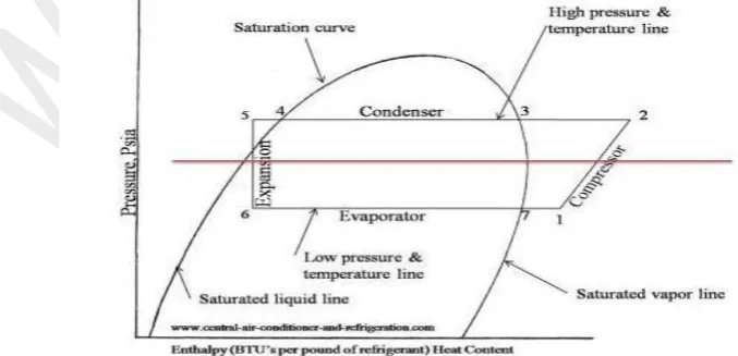
A simple vapour compression refrigeration system consists of mainly five components namely compressor, condenser, expansion device, evaporator and a filter/drier. The following study is focused towards finding out the effect of the condenser tube on the performance of the refrigeration system. A condenser tube is a small diameter tube which is used for the rejection of heat from refrigerant to surroundings to decrease the temperature of refrigerant or change of phase of the flowing fluid. The pressure difference between the entry and exit ends of the condenser tube is always equal to the discharge pressure of compressor. The diameter of the condenser tube used in the refrigeration appliances varies from 3mm to 4.5mm. The effect of the condenser tube as well as expander tube has been investigated by many researchers in the past and encouraging results were obtained.
Volume 02, No. 4, April 2016
P
age
179
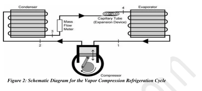
Figure 2: Schematic Diagram for the Vapor Compression Refrigeration Cycle
II. LITERATURE REVIEW
Hirendra Kumar Paliwal and Keshav Kant[1] (2006) developed a flow model for designing and studying the performance of helical coiled capillary tubes and to mathematically simulate a situation closer to one existing in real practice. Homogeneous flow of two phase fluid was assumed through the adiabatic capillary tube. The model included the second law restrictions. The effect of the variation of different parameters like condenser and evaporator pressures, refrigerant flow rate, degree of sub cooling, tube diameter, internal roughness of the tube, pitch and the diameter of the helix and the length of the capillary tube were included in the model. Theoretically predicted lengths of helical coiled capillary tube for R-134a are compared with the length of the capillary tube actually required under similar experimental conditions and majority of predictions were found to be within around 10% of the experimental value.
M.Y.Taib[2] et al. (2010) studied the performance of a domestic refrigerator and developed a test rig from refrigerator model NRB33TA. The main objective of the performance analysis was to obtain the performance of the system in terms of refrigeration capacity, coefficient of performance (cop), and compressor work by determining three important parameters which are temperature, pressure and refrigerant flow rate. The analysis of the collected data gave the cop of the system as 2.75 while the refrigeration capacity was ranging from 150 watt to 205 watt.
J.K.Dabas[3] et al. (2011) studied the behavior of performance parameters of a simple vapour compression refrigeration system while its working under transient conditions occurred during cooling of a fixed mass of brine from initial room temperature to sub-zero refrigeration temperature. The effects of different lengths of capillary tube over these characteristics were also investigated. The investigation showed that with constantly falling temperature over evaporator, refilling of it with more and more liquid refrigerant causes increase in heat transfer coefficient which maintains the refrigeration rate at falling temperature. The study revealed that larger capillary tubes decreases the tendency of refilling but offers less evaporator temperature while shorter capillary tubes ensure higher cop initially but it deteriorates at a faster rate in lower temperature range.
Volume 02, No. 4, April 2016
P age
180
Neeraj Upadhyay[5] study showed that COP of Vapour Compression Cycle is increased by lowering the power consumption /work input or increasing the refrigerating effect. By using sub-cooling and using diffuser at condenser inlet refrigerating effect increases and power consumption or work input decreases. Thus performance of cycle is improved. High velocity refrigerant has various serious effect on vapour compression refrigeration system such as liquid hump, undesirable splashing of the liquid refrigerant in the condenser and damage to the condenser tubes by vibration, pitting and erosion. Diffuser is such a device to reduce high velocity of refrigerant is the conversion of some amount of kinetic energy into pressure energy without work consumption. Condenser tubes will be saved from vibration, pitting and erosion. It will save from the phenomenon of liquid hump. The heat transfer will increase due to increase in pressure and temperature. Hence, there will be reduction in size and cost of the condenser.
Experimental analysis has been carried out by R. T. Saudagar, U. S. Wankhede [6] to study the effect of diffuser at condenser inlet on vapour compression refrigeration system. Four diffusers
were tested with divergence angles of 10⁰, 15⁰, 20⁰ and 30⁰. At particular discharge pressure,
diffuser with divergence angle 15⁰ gave the better results as compared to other diffusers at same
discharge pressure for the same inlet and outlet diameters of diffuser. Diffuser at condenser inlet resulted gain in pressure. The discharge pressure increased by nearly 5%., compressor work is reduced by nearly 14%. Percentage of increase in COP was approximately 16% and rate of heat rejection increased by nearly 4%. By incorporating the diffuser at condenser inlet, size of condenser can be reduced.
Bergander[7] investigated new regenerative cycle for vapour compression refrigeration which described a novel approach to the Rankine vapour compression cycle for cooling and refrigeration. Generally expansion valve, capillary tube and other throttling valves are used in vapour compression refrigeration system to lower the pressure of liquid refrigerant and low pressure refrigerant delivers to the evaporator. Specific innovation was two phase ejector applied as second step of compression, which results reduction in mechanical work required for compressor for the process of compression of gas at the expense of available kinetic energy of gas in the ejector. Injected liquid phase into accelerated flow of the vapour phase and separated working medium to high and low density phases achieved gain in efficiency. In this, compression ratio was lowered by decreasing discharge pressure from the compressor, not by increasing suction pressure. Results obtained were showed that pressure on the ejector increased by 15-16% and prototype achieved energy saving of 16%.
Linton et al. [8] (1992) experimentally investigated the effect of condenser liquid sub cooling on a refrigeration system performance. Results showed that the cooling COP and refrigeration capacity of all three refrigerants benefited from sub cooling increase (from 6°C to 18°C): R134a (12.5%), R12 (10.5%) and R152a (10%), while condensing temperature was kept artificially constant.
III. METHODOLOGY
The experimental study was done in the refrigeration and air conditioning laboratory in the best possible controlled environment. Hermetic sealed compressor unit and tubular condenser unit were used. The evaporator unit was properly insulated to the best of the effort so as to minimize
the heat leakage into the system from the surrounding. Copper tubes of diameter ¼ inches, 3/8th
inch & 5/16th inch were used for providing the supply and return lines to the flowing fluid in the
Volume 02, No. 4, April 2016
P
age
181
The filter/drier does not allow the ice to be formed in the flow lines by absorbing all the moisture particles present in the flowing fluid. Two analogue pressure gauges were used to determine the pressure of the flowing fluid in the high pressure and the low pressure line. The pressure gauge in the high pressure line was installed just after the filter/drier and just before the capillary tube. Another pressure gauge was installed in the low pressure return line to measure the pressure of the fluid returning back to the compressor. A thermometer was used to determine the temperatures that were to be used in the analysis of the system. The readings of the temperature and pressure were plotted on the PH chart and the corresponding enthalpies were noted down and from the obtained values of the enthalpies, the parameters like the refrigeration effect and the compressor work were determined. The carnot COP of the system was determined by using the temperature limits of the system and the actual COP of the system was determined by taking the ratio of the refrigeration effect and the compressor work obtained from the PH chart.
IV. EXPERIMENTAL OBSERVATION AND RESULT DISCUSSION
Condenser tubes of 1/4th Inch, 3/8th Inch and 5/16th Inch were used as the test sections. The
length of each test section was kept constant to 3.5m. For each test section, readings were taken for three distinct configurations i.e. free and forced convection. Every set of readings consists of at least five readings, includes cop of actual, Theoretical and carnot.
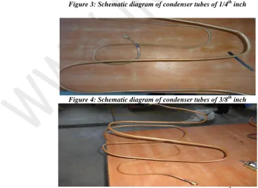
Figure 3: Schematic diagram of condenser tubes of 1/4th inch
Figure 4: Schematic diagram of condenser tubes of 3/8th inch
Volume 02, No. 4, April 2016
P
age
182
Figure 6: Graphical analysis of theoretical cop with pipe diameter (R134a)
This graph shows that the cop of theoretical is more in 3/8th inch pipe having a value of
5.783 in natural convection and 8.6 in forced convection whereas in 5/16th inch pipe and in
1/4th it is quite less.
Figure 7: Graphical analysis of actual cop with pipe diameter (R134a)
This graph shows that the cop of actual is more in 3/8th inch pipe having a value of 0.46 in
natural convection and 0.7 in forced convection whereas in 5/16th inch pipe and in 1/4th it is
quite less.
.
Volume 02, No. 4, April 2016
P
age
183
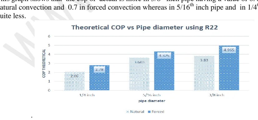
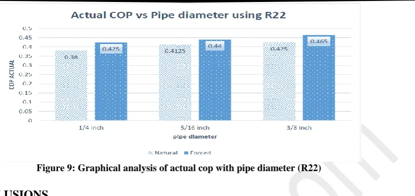
Figure 9: Graphical analysis of actual cop with pipe diameter (R22)
V. CONCLUSIONS
The above mentioned experimental study involved a thorough observation and analysis of the readings and values obtained. The above shown readings, graphs and curves do point out towards some distinct conclusions and inferences which are stated below:-
1. The refrigeration effect produced is maximum for the 3/8th inch condenser tubes and is least
for 1/4th inch condenser tubes for each test section.
2. As the diameter of the condenser tube goes on increasing, the evaporator temperature goes on decreasing as well.
3. As we increase the condenser tube diameter, the mass flow rate of the fluid in the system tends to decrease.
V. REFERENCES
i. Hirendra Kumar Paliwall, Keshav Kant2 , " A model for helical capillary tubes for
refrigeration systems," International Refrigeration and Air Conditioning Conference Purdue University , 2006
ii. M.Y.Taib, A.A.Aziz and A.B.S.Alias, “Performance analysis of a domestic
refrigerator”, National Conference in Mechanical Engineering Research and Postgraduate Students, 2010.
iii. J.K.Dabas, A.K.Dodeja, Sudhir Kumar and K.S.Kasana, “Performance characteristics of
“vapour compression refrigeration system” under real transient conditions”, International Journal of Advancements in Technology, 2011.
iv. F. W. Yu and K. T. Chan, “Application of Direct Evaporative Coolers for Improving the
Energy Efficiency of Air-Cooled Chillers”, A.S.M.E., Vol. 127, August 2005, pp. 430-433.
v. Neeraj upadyay, Analytical Study of Vapour Compression Refrigeration System Using
Diffuser and Sub cooling, IOSR Journal of Mechanical and Civil Engineering (IOSR-JMCE), Volume 11, Issue 3 Ver. VII (May- Jun. 2014), PP 92-97.
vi. R. T. Saudagar, U. S. Wankhede, Experimental Analysis of Vapour Compression
Volume 02, No. 4, April 2016
P
age
184
vii. Mark J. Bergander, New Regenerative Cycle for Vapour Compression Refrigeration,
Final Scientific Report, DOE Award Number: DE-FG36-04GO14327, 30th Sept. 2004 to 30th Sept. 2005.
viii. Linton, J.W., Snelson, W.K., Hearty, P. F., 1992. Effect of condenser liquid subcooling
on system performance for refrigerants CFC-12, HFC-134a and HFC-152a. ASHRAE