International Journal of Research Publications
E-mail address: [email protected].
www.ijrp.org
Analysis and Design of Substructure for Cable-Stayed Bridge
Thazin Theina
ab
Department of Civil Engineering, Technological University (Mandalay), Mandalay, Myanmar
Abstract
Transportation has played a vital role in every aspect of ancient and modern civilization. In this study, substructure of Mone Chaung Bridge is analyzed and designed by using STAAD-Pro software. The required borehole soil data are taken from Ministry of Construction in Myanmar. Firstly, general requirements of substructure are designed such as pier, cap, pile, pile cap and abutment. The proposed Mone Chaung Bridge linking the Padan and Kazunma sections is located on the Pathein- Monywa road in Magway Division, Myanmar which is in seismic zone III. Superstructure of two lanes two spans with 600ft ft is analyzed by STAAD-Pro software. Live loads are applied HS 20-44 according to AASHTO specification. Wind and seismic load are considered from UBC-97 code. Material properties and specifications of concrete are according to ACI 318-05. The concrete compression strength fc̒ (3000psi) and the bending reinforcement yield stress fy (50000psi) are used in substructure. The allowable bearing capacity of the soil is calculated by SPT methods. The load for foundation design is taken from superstructure’s analysis result. In substructure design pile capacity, pile caps and abutments which are designated manually and checked by ACECOMS GEAR design software. In pile foundation design, the pile diameter is 5 ft, required pile length is 94ft and #8 bars are used for reinforcement steel. Abutment is designed deal with the critical loads from superstructure. The settlement effects and liquefaction are satisfied. The sliding, overturning and stability of abutment are also satisfied. Finally, conclusions and recommendations are presented. © 2018 Published by IJRP.ORG. Selection and/or peer-review under responsibility of International Journal of Research Publications (IJRP.ORG) Keywords; AASHTO, ACECOMS GEAR, ACI 318-05, Cable-stayed Bridge, STAAD-Pro.
1. Introduction
Transportation is defined as the movement of freight and passengers from one location to another. The movement can be carried out through a variety of modes, use different energy sources, and serve different needs. The growth and decline of nation in history has been related to their ability to move on and protect their trade and military route, harbors and navigable rivers. The need to link the activities taking place in separate locations and to convey persons and over these links has increase as society has become more complex. Success in meeting this need has been a major contributor to increase standards of living around the world. A developing country, Myanmar is rich in land resources and abundant water resources. Myanmar is agricultural based nation and economic condition is improved more and more mostly rely on land and farm products. Roads are constructed for the transportation of land and farm product. These roads cross many obstacles
Available online at www.ijrp.org
International Journal of Research Publications
Volume-34, Issue-1,August 2019
Accepted and Published Manuscript
Analysis and Design of Substructure for Cable-Stayed Bridge
Thazin Thein
PII : Thazin Thein.10034182019671 DOI: 10034182019671
Web: http://ijrp.org/paper-detail/672
To appear in: International Journal of Research Publication (IJRP.ORG)
Received date: 11 Aug 2019 Accepted date: 14 Aug 2019 Published date: 16 Aug 2019
Please cite this article as: Thazin Thein , Analysis and Design of Substructure for Cable-Stayed Bridge , International Journal of Research Publication (Volume: 34, Issue: 1), http://ijrp.org/paper-detail/672
This is a PDF file of an unedited manuscript that has been accepted for publication. As a service to our customers we are providing this final version of the manuscript.
International Journal of Research Publications
E-mail address: [email protected].
Analysis and Design of Substructure for
Cable-Stayed Bridge
Thazin Thein
aabDepartment of Civil Engineering, Technological University (Mandalay), Mandalay, Myanmar
Abstract
Transportation has played a vital role in every aspect of ancient and modern civilization. In this study, substructure of Mone Chaung Bridge is analyzed and designed by using STAAD-Pro software. The required borehole soil data are taken from Ministry of Construction in Myanmar. Firstly, general requirements of substructure are designed such as pier, cap, pile, pile cap and abutment. The proposed Mone Chaung Bridge linking the Padan and Kazunma sections is located on the Pathein- Monywa road in Magway Division, Myanmar which is in seismic zone III. Superstructure of two lanes two spans with 600ft ft is analyzed by STAAD-Pro software. Live loads are applied HS 20-44 according to AASHTO specification. Wind and seismic load are considered from UBC-97 code. Material properties and specifications of concrete are according to ACI
318-05. The concrete compression strength fc̒ (3000psi) and the bending reinforcement yield stress fy (50000psi) are used in
substructure. The allowable bearing capacity of the soil is calculated by SPT methods. The load for foundation design is taken from superstructure’s analysis result. In substructure design pile capacity, pile caps and abutments which are designated manually and checked by ACECOMS GEAR design software. In pile foundation design, the pile diameter is 5 ft, required pile length is 94ft and #8 bars are used for reinforcement steel. Abutment is designed deal with the critical loads from superstructure. The settlement effects and liquefaction are satisfied. The sliding, overturning and stability of abutment are also satisfied. Finally, conclusions and recommendations are presented.
© 2018 Published by IJRP.ORG. Selection and/or peer-review under responsibility of International Journal of Research Publications (IJRP.ORG)
Keywords; AASHTO, ACECOMS GEAR, ACI 318-05, Cable-stayed Bridge, STAAD-Pro.
1. Introduction
Thazin Theina / International Journal of Research Publications (IJRP.ORG)
such as rivers, streams and valleys. To overcome such obstacles, bridges are important roles. All engineers have to consider how to design for bridges. Design of bridge can be divided into two categories; Substructure design and Superstructure design.
Substructures of a bridge are the structure designed to support the superstructure of the bridge. Substructures for bridges fall into two distinct categories i.e. end supports and intermediate supports. The end supports are normally described as the 'abutments', whilst the general term for the intermediate supports of a multi-span bridge is the 'piers'. The abutments and
piers are usually constructed from in-situ concrete, but precast sections can be employed to speed up the construction
process.
Thus substructure covers piers and abutment bodies together with their foundations and also the arrangements above the piers through which the superstructure sits, i.e., bear on the substructure.
2. Parts of The Bridge Substructure
Substructure perform two main functions: transferring superstructure vertical loads to the foundations and resisting horizontal forces acting on the bridge. As a component of a bridge, the abutment provides the vertical support to the bridge superstructure at the bridge ends, connects the bridge with the approach roadway, and retains the roadway base materials from the bridge spans. A pile usually represents a slender structural element that is driven into the ground. However, a pile is often used as a generic term to represent all types of deep foundations, including a (driven) pile, (drilled) shaft, caisson, or an anchor. A pile group is used to represent various grouped deep foundations. A bored pile foundation is constructed with cast-in-place concrete after a hole is first drilled or excavated. Piles are relatively long and generally slender structural foundation member that transmit superstructure load to deep soil layers.
A cable-stayed bridge requires large lateral capacity for its end anchorage which can be huge, a high capacity soil or rock anchor system, a group of driven piles, or a group of large-diameter drilled shafts. Tower foundations of an over-water bridge require large compressive, uplift, lateral, and overturning moment capacities.
3. Analysis Results of Superstructure
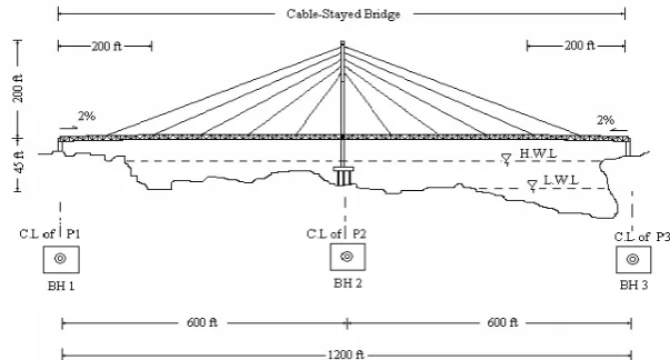
In this study, the required borehole soil data of proposed bridge is taken from existing girder bridge designed by Ministry of Construction. Proposed bridge is cable stayed type bridge which is located in seismic zone 3. The total length of river span is
1100 ft. So the bridge is 1200 ft long which has two symmetrical bays. λ shape box section (outer diameter10ft and inner
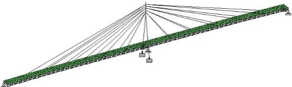
diameter 4ft) rectangular concrete pylon is chosen to design. Section of girder is taken warren truss type steel girder. Roadway width is 24 ft and sidewalk is 4 ft at each side. Superstructure is analyzed by STAAD-Pro software. Live loads are applied HS 20-44 according to AASHTO specification. Lateral loads (Wind and Earthquake) are considered from UBC-97 code. Material properties and specifications of Steel are according to ASTM. The configuration of proposed bridge is shown in fig.1. 3D modeling of proposed cable–stayed bridge and steel truss are shown in fig.2. and fig. 3.
Fig. 2. 3D model of proposed bridge
Fig. 3. Warren truss type steel girder
This structure is considered to apply the loads; Dead Load (self wt, wearing surface, sidewalk & handrail), Live Load (sidewalk), Lane Load (series of truck), Truck Load (HS20-44), Wind Load, Seismic Load.
In this structural analysis of proposed bridge, dead loads are applied as follow;
Unit weight of concrete : 150 pcf
Unit weight of asphalt : 135 pcf
Railing : 150 lb/ft
The live load shall consist of sidewalk load of pedestrians, the weight of the applied moving load of vehicles and lane loading.
Highway loading : HS 20-44 of AASHTO
Sidewalks (dead load) : 112.5 psf
Sidewalks (live load) : 85 psf
Impact Factor : 0.3
The loading on a bridge due to wind force is based on UBC97 and required data for designing wind load are as below;
Exposure type : Type D
Basic wind velocity : 100 mph
Windward wall pressure coefficient : 0.8 Leeward wall pressure coefficient : 0.5
Important factor : 1
At the highest level of heat in Magway Division is 86°F in summer. This temperature is used for design in this study. In this study, the analysis method of earthquake is based on UBC97. The required data for the calculation of earthquake are as follow;
Seismic zone : 3
Soil profile type : SD
Seismic coefficient, Ca : 0.44
Seismic coefficient, Cv : 0.64
Numerical coefficient, Ct : 0.035
Important factor, I : 1.25
Thazin Theina / International Journal of Research Publications (IJRP.ORG)
Table.1. Required support reaction of two inclined pylon
Reactions (K, K-ft) Node -5317 U/S Leg Node -5318 D/S Leg Fx Max: +ve
Min: -ve
58.83 -252.73
58.83 -252.73 Fy Max: +ve
Min: -ve
9259.38 0.00
9712.60 0.00 Fz Max: +ve
Min: -ve
1215.51 0.00
0.00 -1481.26 Mx Max: +ve
Min: -ve
148.5 -4676.730
0.00 -4971.57 My Max: +ve
Min: -ve
522.5 -1142.340
1142.34 -522.52 Mz Max: +ve
Min: -ve
11391.87 -6884.56
11391.87 -6884.56
Table.2. Required support reaction of two end supports
4. Design of Substructure
The design member of substructure contains columns and column cap, bored pile, pile cap and abutments. Firstly, design the number of piles that supported all load in superstructure. The capacity for each pile has calculated based on the borehole data in local report and by using the Meyerhof’s Method. According to site configuration as in fig. 1, there are three boreholes and calculated these capacities and settlements.
4.1. Design the Piles
Design the piles for each borehole and these pile capacities and settlements results are shown in Table 3.
Table.3. Pile capacities and settlements for boreholes
4.2.Design of Piers and Piles Cap
Inproposed cable stayed bridge, the superstructure is supported by three piers i.e. P1, P2 and P3. To calculate the pile cap
design; it is provided the Gear design software.
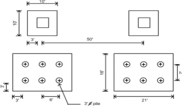
1. Design of a Column and pile cap for main pylon Pier P2
In this proposed bridge, each selected pier size is 10 ft × 10 ft × 3 ft and the distance between two inclined piers is 50 ft
center to center apart. Support reactions of two column legs are described in Table I. So, each column has provided by a pile cap with 6 numbers of 3 ft diameter 70 ft long piles. Geometrical layout of pile caps is shown in Fig. 4. Each pile cap has 21
Reactions (K)
Node -1 Node -122 Node -121 Node - 242 Fx Max: +ve
Min: -ve 0.00 -3243.30 0.00 -2863.40 3243.30 0.00 3037.12 0.00 Fy Max: +ve
Min: -ve 275.76 -61.06 275.77 0.0 241.614 -61.062 242.40 0.0 Fz Max: +ve
Min: -ve 0.00 -160.31 39.86 -92.50 0.00 -160.31 42.70 -92.50 Bore hole No Pile Dia: (Ft) Pile Length (Ft) Qall (Ton) Lateral Capacity (Ton) Uplift (Ton) Settle ments (in)
1 2.5 60 131 479 3127 2.72
2 3.0 70 1300 780 1427 2.83
ft length, 16 ft width and 6 ft transverse and 7 ft longitudinally pile spacing respectively. These data of cap are used in model and reactions of pylons are applied at the center of pile cap. And then the model is analyzed by using Gear software. It gives the final thickness 9 ft. Piles reactions getting from the analysis results are checked with the capacity of manually calculated answers. All vertical and lateral forces are got in the allowable range as shown in Table 4. The results of reinforcement design are 32 #14 at X-direction and 32 #14 at Y-direction. The detail design drawings of pile cap are shown in Fig.5.
Fig. 4. Layout of Column Section and Pile Cap for Pylon P2
Fig. 5. Steel Arrangement of Pile cap 2
Table.4. Piles reactions results for pylon P2
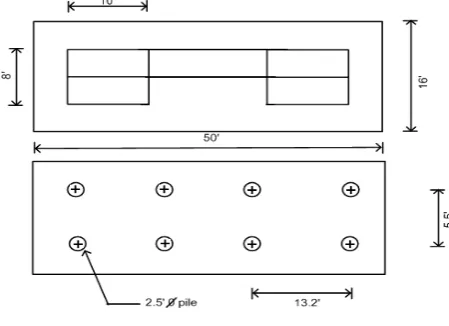
2. Design of a a pile cap and abutments for P1 and P3
Bridge abutments serve to transmit the load from the super structure to the foundation and act as retaining walls to
hold back the earth fill behind them. In this proposed bridge, each abutment has two piers 10 ft × 8 ft × 20 ft with transverse
beam 42 ft × 4 ft × 10 ft size. So each abutment has provided by a pile cap with 8 numbers of 2.5 ft diameter piles.
Geometrical layout and elevation of pile caps are shown in Fig. 6. Each pile cap has 50ft length, 16ft width and 13ft transverse and 5.5 ft longitudinally pile spacing respectively. These data of cap are used in model and reactions and pier weight are applied at the pile cap. And then it is analyzed the model by using ACECOMS GEAR software. It gives the final thickness 5 ft. Piles reactions getting from the analysis results are checked with the capacity of manually calculated answers.
Piles Nz (kip) Vx (kip) Vy (kip)
Allowable Normal Capacity
(kip)
Allowable Lateral Capacity
(kip)
Check Result
PI 1 1153.44 202.59 -42.12 2600 1560 ok
PI 2 892.48 202.59 -42.12 2600 1560 ok
PI 3 631.53 202.59 -42.12 2600 1560 ok
PI 4 2455.00 202.59 -42.12 2600 1560 ok
Thazin Theina / International Journal of Research Publications (IJRP.ORG)
All vertical and lateral forces are got in the allowable range as shown in Table 5. The results of reinforcement design are 10 #14 at X-direction and 29 #14 at Y-direction. The detail design drawings of pile cap are shown in Fig. 7.
Fig. 6. Layout of Column Section and Pile Cap for Two End Supports
Fig. 7. Layout of Column Section and Pile Cap for Two End Supports
Table.5. Piles Reactions Results for Two End Supports
Piles (kip) Nz (kip) Vx
Calculated Normal Pile
Capacity (kip)
Calculated Lateral Pile Capacity
(kip)
Check Result
PI 1 146.60 7.88 260 960 ok
PI 2 145.56 7.88 260 960 ok
PI 3 144.52 7.88 260 960 ok
PI 4 143.49 7.88 260 960 ok PI 5 146.60 7.88 260 960 ok
PI 6 145.56 7.88 260 960 ok
PI 7 144.52 7.88 260 960 ok
5. Discussion and Conclusion
The main objective of the study is to design the substructure of proposed bridge. The proposed Mone Chaung Bridge is one of the large span hybrid cable-stayed bridges in Myanmar. In this paper present that only the substructure of proposed bridge is analyzed and designed. The required input data are taken from Ministry of Construction. This study is to discuss the design calculation of pier cap, column, bored pile foundation and abutment. To design piles, piers and pile cap, the critical loads are obtained from superstructure. The allowable bearing capacities are calculated by using Meyerhof's method. The calculated results of pile diameter are 2.5ft for P1 and P3 and 3 ft for P2. Under each Pylon column has 6 numbers of 3 ft diameter 70 ft long piles. Pylon’s pile cap has 21 ft length, 16 ft width and 6 ft transverse and 7 ft longitudinally pile spacing respectively. The thickness of the Pylon pile cap is 9 ft taken from Gear software. In this proposed bridge, each
abutment has two piers 10 ft × 8 ft × 20 ft with transverse beam 42 ft × 4 ft × 10 ft size. So under each abutment has 8
numbers of 2.5 ft diameter piles. Each pile cap has 50ft length, 16ft width and 13ft transverse and 5.5 ft longitudinally pile spacing respectively. The thickness of the pile cap is 9 ft taken from Gear software. The results of reinforcement design are 10 #14 at X-direction and 29 #14 at Y-direction. According to the results of settlement checking design of pile foundation is satisfactory. The reinforcement is checked and satisfied with maximum spacing and, minimum steel ratio.
It is concluded that can be analyzed and designed the Mone Chaung cable-stayed bridge which is selected to get the optimal configurations. It has been providing the information for feasibility studies to compare with existing and other types of bridge for construction of Mone Chaung bridge. It is known that analysis and designs using software are saving calculation time.
The recommendations for this research are:
The aerodynamic effects should be considered for long span cable-stayed bridges.
It should be analyzed and designed with the unsymmetrical span and single pylon as an alternative study by using the
counter weights.
It should be design with STAAD-Pro latest version which can design the combination model of superstructure and
substructure. No need to do separated design and to use other design software.
Acknowledgements
The author would like to express grateful thanks to Dr. Sint Soe, Rector, Technological University (Mandalay) for his directions and managements. Special thanks are extended to Dr. Nyan Myint Kyaw, Professor, Yangon Technological University for his valuable suggestion and excellent comments to conduct this paper. The author would like to thank her parents, teachers and all of friends for their support and encouragement throughout this research.
References
Ed. Wai-Fah Chen and Lian Duan Boca Raton, "Bridge Engineering Handbook" CRC Press, 2000. Craig. R. F. 1990. Soil Mechanics. Chapman and Hall. New York. Fourth Edition
Texas Department of Transportation, "Bridge Design Manual"
Nilson, A.H and Winter, "Design of Concrete Structures” 12th Edition, McGraw Hill Co., U.S.A. Das. B. M. 1997. Principles of Geotechnical Engineering. PWS Publishing Company. Fourth Edition. Gimsing. N. J. 1998. Cable Supported Bridges Concept and Design. John Wiley & Sons, Inc. Second Edition.
Prakash, Shamsher and Hari D. Sharma. 1990. “Pile Foundation in Engineering Practice”. Canada: John Wiley and Sons, Inc. Ruwan. Rajapakse,CCM,P.E,. 1997. Pile Design for Structural and Geotechnical Engineering.