•
UNISYS
XE500
BTOS
Installation
and Implementation
Guide
Copyright © 1988 Unisys Corporation All Rights Reserved
Unisys is a trademark of Unisys Corporation
Relative to Release Level 7.0
Priced Item
May 1988
Distribution Code SA Printed in U S America
The names, places and/or events used in this publication are not intended to correspond to any individual, group, or association existing, living or otherwise. Any similarity or likeness of the names, places, and/or events with the names of any individual living or otherwise, or that of any group or association is purely coincidental and
unintentional.
NO WARRANTIES OF ANY NATURE ARE EXTENDED BY THE DOCUMENT. Any product and related material
disclosed herein are only furnished pursuant and subject to the terms and conditions of a duly executed Program Product License or Agreement to purchase or lease equipment. The only warranties made by Unisys, if any, with respect to the products described in this document are set forth in such License or Agreement. Unisys cannot accept any financial or other responsibility that may be the result of your use of the information in this document or software material, including direct, indirect, special or consequential damages.
You should be very careful to ensure that the use of this information and/or software material complies with the laws, rules, and regulations of the jurisdictions with respect to which it is used.
The information contained herein is subject to change without notice. Revisions may be issued to advise of such changes and/or additions.
v
About This Guide
This guide contains general information about the
installation and the implementation of the software for the XE520 Shared Resource Processor.
Who Should Use This Guide
This guide is intended for the person who installs, configures, and maintains the XE520 software. Some knowledge of computer operations is necessary.
How to Use This Guide
You do not need to read this guide from cover to cover. It
contains information on many aspects of the XE520, and you may be interested in only some of them at this time.
If you are familiarizing yourself with XEBTOS installation, configuring, and administration requirements, you should read the brief overview in section 1.
In addition, if you look over the table of contents to review the topics before you start, you may find this guide easier to use.
To locate detailed information, refer to the alphabetic index of topics at the back of this guide.
How This Guide is Arranged
The material in this guide is divided into 12 sections, 2 appendixes, a table of contents, a glossary of terms, and an index.
D Section 1 gives an overview of the XE520 BTOS
software installation procedure, including a description of the release media.
vi About This Guide
o Section 3 describes how to use quarter-inch cartridge (QIC) tapes and half-inch tapes, and their tape drives. o Section 4 gives detailed procedures for installing the
XEBTOS system software on the XE520.
o Section 5 gives detailed procedures for installing the BTOS standard software on the XE520.
o Section 6 gives an overview of the system configuration files.
o Section 7 briefly describes system services., such as the AdminAgent, tape servers, and QIC servers.
o Section 8 describes how to configure system services and configuration files for the XE520.
o Section 9 discusses post-configuration tasks that you complete after creating the system configuration files. These tasks include creating BTOS command forms and files, obtaining a list of bad spots, restoring customized files, and backing up your system software.
o Section 10 describes how to install and configure the Queue Manager.
o Section 11 describes how to install, configure, and operate the printer spooler.
o Section 12 describes how to create I/O Device
Configuration Files, and includes information about the mCREATE CONFIGURATION FILE utility.
o Appendix A lists the default system configuration files.
o Appendix B provides hardware configuration information.
Conventions
The following conventions apply to this guide:
o Processor board names refer to both the standard board and the X-Board. For example, CP refers to both CP and CP-X.
About This Guide
Related Product Information
Refer to the following product information for more information about the XE520 or BTOS.
o XE520 System Capabilities Overview
vii
This capabilities overview provides a brief description of the features and capabilities of the XE520 System Shared Resource Processor. It is directed toward the user who wants an introduction to the XE520 system.
o XE500 BTOS Administration Guide
This guide provides administration information for the XE520 BTOS system, including using master utilities, verifying and initializing disks, managing XE520 file systems, establishing system and file security, using the command line interpreter, monitoring XE520 processor activity, troubleshooting, and configuring hardware.
o BTOS II Standard Software Operations Guide
This guide contains introductory, procedural, and reference information for using the standard features of XE520 and workstation BTOS. It includes software installation procedures, system configuration
instructions, and explanations of standard Executive commands.
o BTOS II Standard Software Operations Quick Reference Guide
This guide is for experienced operators and administrators who are already familiar with the material presented in the BTOS II Standard Software
Operations Guide. It provides an alphabetical listing of the XE520 and workstation BTOS commands and their command forms.
o XE500 BTOS Operations Guide
This guide provides information on performing those XE520 BTOS tasks that are routinely performed by anyone using the XE520 system.
o BTOS II Customizer Programming Guide
viii About This Guide
D XE500 BTOS Debugger Operations Guide
This guide describes how to use the XE520 BTOS Debugger.
D BTOS II System Status Codes Reference Manual
ix
Contents
About This Guide . . . v
Who Should Use This Guide... ... v
How to Use This Guide. . . v
How This Guide is Arranged. . . v
Conventions . . . vi
Related Product Information... . vii
Section 1: Overview of the XE520 BTOS Software
Installation . . . 1-1 XE520 Software Release Media. . . 1-1 Processor Naming Conventions... ... 1-2
Section 2: Starting Up the System... 2-1 XE520 Controls ... ... _... 2-1 Powering Up the XE520... 2-3
Booting a BTOS Workstation from
the XE520 . . . 2-5 Booting a Workstation Having Standalone
BTOS Software. . . 2-5 Booting a Workstation Having No Standalone BTOS Software.. 2-7 Determining Your Workstation Operating System Number.... . 2-7 Handling BTOS Workstation Bootup Problems... ... 2-9
Powering Down the XE520 ... 2-9
Section 3: Using QIC and Half-Inch Tapes... 3-1 Handling QIC Tapes . . . 3-1 Operating the QIC Tape Drive. . . 3-3
Inserting a QIC Tape. . . 3-3 Removing a QIC Tape. . . 3-5
Retensioning a QIC Tape. . . 3-5
Handling a Half-Inch Tape. . . 3-5
Caring for the Half-Inch Tape Drive... ... ... 3-6
Loading a Half-Inch Tape. . . 3-6
Removing a Half-Inch Tape... 3-7
Section 4: Installing the XE520 BTOS System
Software. . . 4-1 Updating versus Initializing... ... ... 4-1 Initializing Your System. . . 4-2
Hardware Requirements ... 4-2
Installing the XE520 Software. . . 4-3
x
Section 5: Installing Workstation Software ... .
Installing Standard Workstation Software . ... . Installing the Workstation Utilities Software . ... . Installing Cluster Workstation Software . ... . Installing Workstation Language Development Software . .. .
Section 6: Overview of System Configuration Files . .. .
The Master Configuration File . ... .
Sample Master Configuration File ... .
Processor Configuration Files .. ... . Dynamic Block Allocation ... . File and Disk Processor Configuration Files ... . Disk Device Configuration Used by the System . ... . Cluster and Terminal Processor Configuration Files ... .
RS-232-C Port Line Entries ... . RS-422 Cluster Port Line Entries ... . Default Cluster Processor Configuration File ... .
Storage Processor Configuration File . ... . I/O Device Configuration Files . ... .
Disk Drive Configuration Files ... . Printer Configuration Files ... . Half-Inch Tape Drive Configuration Files ... . QIC Tape Drive Configuration File ... . Communication Device Configuration Files ...•...
Section 7: Overview of System Services ... .
Processor Initialization Files . ... .
Format for Run Statements ... . Creating Partitions ... .
AdminAgent ... .
Obtaining AdminAgent Status Information ... .
Queue Manager . ... . Printer Spooler Managers . ... . mQIC Server . ... '.' ... . mTape Server . ... . Buffering for the QIC and Half-Inch Tape Servers . ... .
mQIC Server ...•... mTape Server ... .
Section 8: Configuring System Services . ... .
Master Configuration File . ... . Processor Initialization Files . ... . Processor Configuration Files . ... . When to Use the mBTOS CONFIG Utility ... . Creating System Configuration Files . ... . Starting the mBTOS CONFIG Utility .... ... . Creating the Default Versions of All Files ... . Modifying the Master Configuration File . ... .
Adding Processor Entries ...•.•...•..•...
Contents
Deleting Processor Entries ... . Selectively Creating or Modifying Processor Initialization Files ... . Creating the Default Version ... . Modifying an Existing File or Creating a Nondefault File ... . Selectively Creating or Modifying Processor Configuration Files ... . Creating the Default Version ...•... Modifying an Existing File or Creating a Nondefault File ... . Adding a TP RS-232-C Port Entry ... . Adding a CP RS-232-C Port Entry ... . Adding a CP RS-422 Cluster Line Entry ... . Deleting A Port or Block Entry ... . Adding or Modifying an X, Y, or Z Block Entry ... . Guidelines for Running System Services ... . mBTOS CONFIG -Old Files ... . Rebooting the System After Running mBTOS CONFIG .... .
Section 9: Post-Configuration Tasks ... .
BTOS Command Forms and User Command Files ... . Creating the Command Forms and Command Files ... . Recording System Disk Bad Spots ... . Listing Disk Bad Spots ... . Restoring Customized Files ... . Backing Up System Software .•...
Section 10: Configuring the Queue Manager ... .
The Queue Index File ... . Installing the Queue Manager ... . Stopping the Queue Manager ... . Queue Requests ... .
Section 11: Configuring the Printer Spooler ... .
Operating the Printer Spooler ... . Printer Spooler Queues ... . Sample Printer Spooler Queue Entries ... . The Spooler Configuration File ...•... Sample Spooler Configuration File ... . Printer Configuration File ... . Serial Printer Channel Entries ... . What the Printer Spooler Does ... . Modifying the Printer Spooler Operation ... . Adding a Printer ...•...•... Moving a Printer ...•... Removing a Printer ... . Running a Workstation Printer Spooler ... . Printer Translation Files ...•... Creating the Source File ...•...•... Creating a Translation File ... .
xii Contents
Section 12: Creating I/O Device Configuration Files. .. 12-1
I/O Device Configuration File Names... 12-1
Executing the mCREATE CONFIGURATION FILE Utility. . . . 12-2 Default Parameter Values. . . 12-2 Prompt Instructions. . . .• . . . •. 12-2 Device Type Prompt... 12-3 Tape Parameter Prompts. . . 12-4 QIC Tape Parameter Prompts. . . .. . . .. . . •. 12-4 Parallel Printer Parameter Prompts. . . .. . . .. . . 12-4 Serial Printer Parameter Prompts. . . . .. . . • . 12-6 Communications Device Parameter Prompts... ...•. 12-7
Maximum Tape Record Size for mTAPE Utilities. . . 12-9
Appendix A: Default System Configuration Files... . .. . A-I mBTOS CONFIG General Default Initialization Files. . . A-I mBTOS CONFIG General Default Configuration Files.. ... A-2 Restricted Mode System Configuration Files. . . A-4 Printer Spooler Configuration Files. . . .• . . . A-6 Disk Device Configuration Files ... A-6
Appendix B: Hardware Configuration Information... B-1
Glossary . ... Glossary-1
Figures
2-1 2-2 3-1 3-2 3-3 3-4 4-1 4-2 5-1 8-1 8-2 8-3 8-4 8-5 8-6 8-7 8-8 10-1 11-1B-1
B-2B-3
Sample XE520 Base Enclosure Front Panel .. XE520 Enclosure POWER ON/OFF Switch .. . Components of a QIC Tape ... . QIC Tape Write-Protect Plug Positions ... . The QIC Tape Drive ... . Inserting the QIC Tape ... . Recommended mlVOLUME Responses for XE520-4 Systems ... . Recommended mlVOLUME Responses for XE520-5 and -6 Systems ... . Rebooting Instructions ... . Default Menu ... . Main Menu ... . Function Menu ... . Add Menu ... . JCL Default Menu ... . JCL Function Menu ... . CN F Default Menu ... . Change Line Menu ... . mlNSTALL QUEUE MANAGER Command Form ... . MAKE TRANSLATION FILE Command Form. Built-in Disk Device Naming Conventions ... Built-in Disk Device Naming Conventions for DPOO ... . Processor Board Numbering Scheme ... .
xv
Tables
1-1 Processor Board Designations . ... 1-2 2-1 Keyswitch Positions on the XE520 . ... 2-2 2-2 BTOS Workstation Operating System
Numbers ... . 2-8 4-1 XE520 Drive Types and Menu Responses .. .. 4-8 8-1 XE520 BTOS System Services and Run Files. 8-21 8-2 Restrictions for XE520 BTOS System
Services ... 8-21 10-1 Queue Types . ... 10-2 10-2 mlNSTALL QUEUE MANAGER Command
Fields .. ... 10-4 11-2 MAKE TRANSLATION FILE Command Form
Section 1
Overview of the XE520 BTOS
Software Installation
To install the XEBTOS software, you perform two major tasks in the following order:
1 You load the XE520 BTOS software onto the XE520 system disk.
2 You load the workstation BTOS software from floppy disks onto the XE520 system disk using workstation software installation procedures.
1-1
To implement the software, you perform two major tasks in the following order:
1 You create system configuration files using the mBTOS CON FIG utility (refer to section 8).
2 You perform the necessary post-configuration tasks such as backing up your system files, creating BTOS master command sets, configuring the AdminAgent, configuring the Queue Manager, configuring printer spooler files, and creating input/output (I/O) device configuration files.
XE520 Software Release Media
The XE520 BTOS system software is available on the following types of release media:
o half-inch tapes
o quarter-inch cartridge (QIC) tapes
If your XE520 has an FP master processor, you use the XE520 BTOS system software that is distributed on QIC tape. If your XE520 has a DP master processor, you use the XE520 BTOS system software that is distributed on QIC or half-inch tape.
In addition, you should also have a BTOS workstation software release package on floppy diskettes. You use the diskettes to load the workstation system and
1-2 Overview of the XE520 BTOS Software Installation
Processor Naming Conventions
XE520 processor names take the form Zpnn, where Zp is the processor type mnemonic and nn is the number of that type in the system. Table 1-1 lists the processor types and their two character mnemonic. Appendix C shows the processor board numbering scheme.
Table 1-1 Mnemonic
FP or FP-X DP or DP-X CP or CP-X SP or SP-X TP or TP-X
Processor Board Designations Processor Type
File Processor Disk Processor Cluster Processor Storage Processor Terminal Processor
Note: Depending on the model, a processor board can have 256 or 768 Kb of RAM memory. You can increase the memory of a processor with 256 Kb of RAM memory to 768 Kb by
connecting a 512 Kb Memory Expansion (ME) board to it. Although the standard processor boards with 256 Kb of RAM memory are still supported for release 7.0, Unisys now provides X-Boards, which contain 768 Kb of RAM memory directly on the processor board.
[image:17.404.34.325.160.346.2]Section 2
2-1Starting Up the System
This section describes the following tasks: o using the XE520 front panel controls
o powering up and powering down the XE520 enclosures
o booting the XE520
o booting a BTOS workstation from the XE520
The discussion of the start-up procedure assumes that you know how to power up and power down any Unisys BTOS-based workstations that are part of the system. It also assumes that you know how to use floppy disks with the workstation floppy disk drives. If you are unfamiliar with the operation of these workstations, you should read through your Standard Software documentation before proceeding.
XE520 Controls
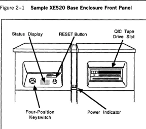
All of the XE520 controls, except the POWER ON/OFF switch, are part of the base enclosure front panel. The front panel (shown in figure 2-1) is located just above the front door of the base enclosure.
The front panel consists of the following components: o four-position keyswitch
o STATUS display
o RESET button
o power indicator
o QIC tape drive slot (optional)
The keys witch setting determines the operating mode of the XE520. You use the control panel keys that were packed with the XE520 to turn the keyswitch. You select the operating mode by turning the key to th~ desired position. You lock the keyswitch at a selected position by removing the key.
2-2 Starting Up the System Figure 2-1 Sample XE520 Base Enclosure Front Panel
Status Display RESET Button ole Tape Drive Slot
Four-Position Keyswitch
Power Indicator
Table 2-1 Keyswitch Positions on the XE520 Keyswitch
Position XE520 Operating Mode
STOP STOP places the system in a reset state and prevents anyone from using it.
MANUAL MANUAL enables the RESET button and boots the system in manual mode.
REMOTE
NORMAL
REMOTE is used during initial system software installation. Once you have installed the software, you use this keyswitch position to troubleshoot system problems.
[image:19.403.32.321.19.526.2] [image:19.403.34.322.54.308.2]Starting Up the System 2-3
Because the MANUAL keyswitch position enables the RESET button, which could be pressed accidentally during system operation, you should generally use the NORMAL keyswitch position. If you have to reset the system for any reason, you can do so by turning the key to STOP and then back to NORMAL.
The STATUS display shows status codes that indicate the operating status of the system.
The power indicator lights up when the system is turned on and the internal power supply is operating properly.
You can use removable media (QIC tape or half-inch tape) to load system software. This media provides backup storage for the BTOS file system. If your base enclosure does not have a QIC tape drive slot, the removable medium for your system is half-inch tape. Refer to section 3 for information about using QIC and half-inch tape.
Powering Up the XE520
Caution: Whenever you power up the XE520, make sure that the removable medium drive is empty and the keyswitch is set to STOP.
To power up the XE520 system, complete the following:
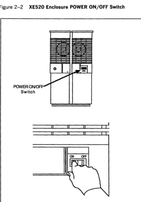
1 Locate the POWER ON/OFF switch (refer to
figure 2-2) at the rear of each enclosure in the system and turn each enclosure to the ON position.
When powering up enclosures in a multi-enclosure system, start with the base enclosure, then power up the second enclosure, the third enclosure, and so on.
If you have powered up correctly, the power indicator at the front panel of each enclosure should be lit, the ST A TUS display at the base enclosure should show the value 00, and you should hear the fans and feel a steady flow of air from the rear ventilation grill of each enclosure.
2-4 Starting Up the System
2 Once the enclosures are powered up, turn the keyswitch from STOP to MANUAL, REMOTE, OR NORMAL,
depending on the operating mode in which you want the system to run.
Refer to table 2-1 and to the XE500 BTOS
[image:21.404.34.320.164.573.2]Administration Guide for more information on operating modes.
Figure 2-~ XE520 Enclosure POWER ON/OFF Switch
POWER ON/OFF Switch
Starting Up the System
Booting a BTOS Workstation from
the XE520
You can operate a BTOS workstation as a standalone computer or as a cluster workstation connected to a master.
2-5
When you power up your workstation, the system first attempts to boot from a diskette in the floppy drive. If the floppy drive is empty or contains an unbootable diskette, the system then attempts to boot from the local hard disk.
If the hard disk does not contain bootable software, the system then attempts to boot from the cluster master (the XE520, for example).
How you boot up your workstation determines the version of workstation BTOS that is loaded into the workstation. The version of workstation BTOS software that is loaded into your workstation determines whether the workstation operates in standalone or cluster mode.
BTOS workstations connected to the XE520 run as cluster workstations. As a result, the XE520 serves as the master, providing services that can be shared by the cluster workstations connected to it.
To configure your workstation to run in cluster mode, you must follow a separate bootup procedure for each of the following workstation configurations:
o a BTOS workstation on which system software has been installed (it contains a [sys]<sys>Syslmage.sys file)
o a BTOS workstation with no standalone BTOS in its local file system
Booting a Workstation Having Standalone
BTOS Software
2·6
Starting Up the SystemHowever, to access the XE520's storage devices and its local hard disk, you must configure your BTOS workstation as a cluster workstation. This downloads (sends) the workstation cluster-mode version of BTOS from the XE520 to your workstation.
One advantage to using your workstat!ion in a standalone environment is that your operating system still runs if the XE520 is shut down. However, when the XE520 is brought up again, you must reboot your workstation (using the following procedures) to return it to the cluster mode.
Caution: If a workstation connected to the XE520 is attempting to operate as a master (that is, if a workstation with standalone workstation software is booted up locally while the XE520 is operating), the system will crash.
To boot your BTOS workstation from the XE520, complete the following:
1 Be sure that the XE520 has been successfully powered on (a 20 appears in the STATUS display).
2 While holding down the Spacebar on your BTOS workstation, power up or reboot your workstation. The system displays the Read Only Memory (ROM) number and then a series of characters (such as B, C, D, L, M, P, T:). The cursor appears after the colon.
3 Release the Spacebar.
4 Type the letter T (the T stands for type of operating system).
The system displays OS: and the cursor. (The
recommended operating system (OS) number may also !>e displayed.)
This prompt is a request for the operating system number of the workstation. To learn the appropriate number for your workstation type, refer to Determining Your Workstation Operating System Number, later in this section.
Starting Up the System 2-7
6 Press RETURN.
The system responds by again displaying the series of characters, followed by the cursor.
7 Enter a B (the B stands for boot).
The system responds by displaying L ... This response indicates that the workstation is going through the boot-up process.
When the boot-up process is complete, the signon form appears on the screen. You can now use your
workstation as part of the XE520 system.
Booting a Workstation Having No Standalone
BTOS Software
If your BTOS workstation does not have a standalone version of BTOS stored locally on a hard disk or floppy disk, use the following procedure to boot it from the XE520:
1 Be sure that the XE520 has been successfully powered on (a 20 appears in the STATUS display).
2 Power up your BTOS workstation.
The workstation automatically boots from the XE520 when it is powered up or rebooted.
The system responds by displaying L ... This response indicates that the workstation is going through the boot-up process.
When the boot-up process is complete, the signon form appears on the screen. You can now use your
workstation as part of the XE520 system.
Determining Your Workstation Operating
System Number
When a BTOS workstation is booted from the XE520, the XE520 loads the workstation's operating system (or system image) into the workstation's local memory.
BTOS has been modified to make it compatible with different workstation hardware configurations. Therefore, there are unique BTOS versions for the different
2-8 Starting Up the System
To determine your workstation model, locate the Unisys identification plate on the bottom of the workstation's CPU module.
Table 2-2 lists the workstations and their corresponding BTOS operating system numbers.
Table 2-2 BTOS Workstation Operating System Numbers Workstation Model
824 (no local file storage)
826 (hard disk)
826 (floppy drives/no hard disk)
826 (no local file storage)
827 (hard disk)
827 (floppy drives/no hard disk)
827 (no local file storage)
828 (hard disk)
828 (floppy drives/no hard disk)
828 (no local file storage)
838 (hard disk)
838 (floppy drives/no hard disk)
838 (no local file storage)
Operating System Number
200
250
251
252
125
126
127
240
241
242
230
231
[image:25.404.40.339.136.413.2]Starting Up the System 2-9
Handling B10S Workstation Bootup Problems
As part of the bootup process, a BTOS workstation runs through a self-diagnostic test. If an error message appears on the screen, refer to your Status Codes documentation.
If you suspect that you responded to a system prompt with incorrect information, reboot your workstation and
complete the rest of the bootup procedure.
If you reboot your workstation and still receive unexpected system information or prompts, verify the following: o Be sure that you are using the proper bootup procedure. o For a workstation with a local standalone operating
system, be sure that you correctly determined the workstation model/type and the correct operating system number for that type.
Powering Down the XE520
To power down the XE520, use the following procedure:
1 Make sure that all users are logged off, and that workstations and peripheral devices (printers, tape drives, etc.) are turned off.
2 Make sure that no tape is currently mounted. 3 Turn the keyswitch on the base enclosure to STOP. 4 Power down each enclosure in the system, starting with
Section
3
3-1Using QIC and Half-Inch Tapes
QIC tapes provide you with portable media on which to store information. On the XE520 system, they also provide you with the source for the initial system software and for future software updates. You can also use them as backup storage devices.
Handling QIC Tapes
When handling QIC tapes, remember the following:
o Do not touch or manually move the magnetic tape inside the cartridge.
o Store cartridges in their cases in a dry area at room temperature. Unlike half-inch tapes, it is not necessary to store QIC tapes vertically.
o Keep QIC tapes away from magnetic devices, such as CRT screens.
Under certain conditions, you should pack (rewind) the QIC tape to ensure that the tape operates properly during I/O operations. If any of the following conditions apply, use the mQIC RETENSION command to rewind the QIC tape before using it:
o excessive read/write errors (more than 50 software errors per pass)
o exposure of the cartridge to temperatures outside the range of 40°F to 110°F (5°C to 44°C)
o prolonged cartridge storage (more than two weeks) o physical shock to the cartridge (such as dropping it or
dropping something on it)
For information on executing the mQIC RETENSION command, refer to Retensioning a QIC Tape, later in this section.
3-2 Using QIC and Half-Inch Tapes
Figure 3-1 Components of a QIC Tape
Write-Protect Plug Protective Door
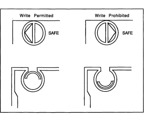
Figure 3-2 QIC Tape Write-Protect Plug Positions
Write Permitted Write Prohibited
[image:29.399.43.330.84.275.2] [image:29.399.44.330.329.561.2]Using QIC and Half-Inch Tapes 3-3
Operating the QIC Tape Drive
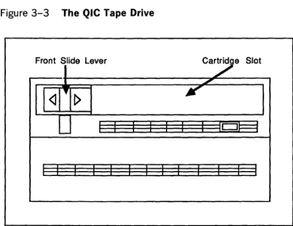
You control the QIC tape drive using the front slide lever and the cartridge slot (shown in figure 3-3).
The front slide lever locks the QIC tape in the drive. The red indicator light on the right side of the drive is on whenever the system is retrieving or storing information.
Caution: Do not push the front slide lever when the indicator light is on; you could interrupt a write operation to the tape.
Inserting a QIC Tape
To insert a QIC tape, use the following procedure:
1 Be sure that the XE520 base enclosure is powered up.
2 Remove the QIC tape from its case.
3 Insert the QIC tape into the drive, with the cartridge protective door facing left and the base plate of the cartridge facing down (refer to figure 3-4).
4 Push the QIC tape into the drive until it descends into the tape drive.
5 Move the front slide lever to the right until it reaches the lever stop.
This secures the cartridge and brings the head assembly to its correct operating position.
3-4 Using QIC and Half-Inch Tapes
Figure 3-3 The QIC Tape Drive
Front Slide Lever
I>
[image:31.404.39.329.56.279.2] [image:31.404.38.324.267.511.2]Using QIC and Half-Inch Tapes
Removing a QIC Tape
To remove a QIC tape, use the following procedure:
1 Make sure the drive indicator light is off.
3-5
2 Move the front slide lever to the left until it reaches the lever stop.
The head assembly in the drive retracts and the protective door on the cartridge closes. A cartridge ejector automatically raises the cartridge out of the drive and slowly pushes it forward.
3 Remove the QIC tape and return it to its case.
Retensioning a QIC Tape
You use the mQIC RETENSION command to rewind a QIC tape; this retensions (packs) the tape.
To retension a QIC tape using the mQIC RETENSION command, complete the following:
1 Insert the QIC tape into the QIC tape drive.
2 Type mQic Retension at your workstation's Executive command line.
3 Press GO.
Handling a Half-Inch Tape
When handling half-inch tapes, be careful not to touch the first few inches of the tape so that you do not lose the identifying information in the first tape file.
3-6 Using QIC and Half-Inch Tapes
Caring for the Half-Inch Tape Drive
The tape transport (drive) has two heads, one behind the other, that float very close to the tape media, and read and write to it.
When the drive is writing, the first head writes, while the second head, set at low gain, reads behind it to verify the quality of the writing. When the drive is reading, the read head is set at high gain for more sensitivity.
If the drive is writing and the second head cannot read what the first head has just written, the system reports a write error.
If you are experiencing several errors, you should check to make sure that the drive heads are clean; dirty heads are the most frequent cause of errors. If you are using the drive heavily, you should clean the drive heads everyday. Otherwise, weekly cleanings are recommended.
Loading a Half-Inch Tape
To load a half-inch tape, complete the following:
o Attach a write-enable ring on the back of the tape reel of a 2400-foot, half-inch magnetic tape.
o Insert the reel into the tape drive and close the door. o Press Load/Rewind (on a Cipher drive) or
Load/Online (on a Pertec drive).
o The indicator light flashes while the tape is
automatically loaded. The tape is finished loading when the light stops blinking and remains lit.
o Press Online (on a Cipher drive) or Load/Online (on a Pertec drive).
Using QIC and Half-Inch Tapes 3-7
Removing a Half-Inch Tape
To remove a half-inch tape, complete the following: o Press Online (on a Cipher drive) or Load/Online (on a
Pertec drive) to make sure that the tape drive is offline. o Press Unload twice (on a Cipher drive) or Rewind
Section 4
4-1Installing the XE520 BTOS System
Software
These software installation procedures assume that you are familiar with using portable media (QIC tapes and
half-inch tapes). If you are unfamiliar with portable media, refer to section 3.
The workstation you use during installation must have a floppy disk drive and must be connected to the first Cluster Processor (CPOO) in the XE520.
If you are loading software from half-inch tape, the tape drive must be connected to the first Disk Processor (DPOO).
If your system does not have a DP, the tape drive must be connected to the first Storage Processor (SPOO).
These workstation and tape drive restrictions are necessary because the system recognizes only the first processor of each processor type during certain parts of the installation and implementation procedures.
Updating versus Initializing
Initializing your system erases the existing data and files on the volume. Before you load new software, initializing your system ensures that all indicators and constants are set to prescribed conditions and values.
Updating your system allows you to save customized system configuration files. However, when you update your system, old and incompatible files that you do not delete may corrupt your system or unnecessarily use disk space. In addition, customized BTOS processor operating systems cannot be used and are overwritten during the installation procedure.
Note: Although it is not required, it is highly recommended that you initialize your system before you install the XEBTOS 7.0 system software.
4-2 Installing the XE520 BTOS System Software
When updating your system, you can save the following types of system configuration files:
o processor initialization files o processor configuration files
o device configuration files (that is, files created through the mCREATE CONFIGURATION FILE utility)
o the queue index file, [sys]<sys>queue.index
o the printer spooler configuration files--for example, [sys]<spl>splcnfg.sys (refer to section 12)
Changes are required for some processor configuration and initialization files.
Initializing Your System
This section explains how to install the XE520 BTOS
system software onto your system, and includes procedures for initializing your system disk.
The software covered in this section is available on QIC or half-inch tape. The installation procedure is nearly the same for each medium. Both media come with a floppy diskette that you insert into your workstation's floppy drive to start the installation procedures.
Hardware Requirements
Before installing XE520 BTOS system software, verify the following hardware requirements:
o The RS-422 cable must be attached to XE520 on channel la, 1b, 2a, or 2b on the CP board. The RS-422 cable must also be attached to the BTOS workstation in one of the cluster communication slots.
Installing the XE520 STOS System Software
Installing the XE520 Software
To install the XE520 system software, complete the following:
4-3
1 Insert the appropriate floppy disk for your workstation into the disk drive.
2 Power up or reset the workstation.
The workstation boots from the floppy disk and then displays the Signon screen.
3 At the Signon screen, press GO.
4 Verify that the XE520 is powered up and that the key on the front status panel is in the STOP position. 5 Depending on the medium you use, load either the QIC
tape or the half-inch tape.
6 Turn the front panel key on the XE520 to the MANUAL position.
The XE520 now boots up from the tape. This takes approximately five minutes.
When it finishes, the system displays a menu containing the following options:
o
= Set Path / Enter Password1 = Initialize a Volume
2 = Restore Volume from Tape
3 = Change Volume Name
4 = Backup a Volume to Tape
7 Type 1.
8 Press RETURN.
The system displays the mIVOLUME command form parameters as a series of prompts asking you to supply information.
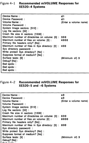
4-4 Installing the XES20 BTOS System Software Figure 4-1 Recommended mlVOLUME Responses for
XES20-4 Systems
Device Name: : d 1
Device Password: : d 1
Volume Name: : (Enter a volume name) Volume Password: :
System Image sectors: [512] :
Log file sectors: [32] :
Crash file size in sectors: [1536] :
Maximum number of directories on volume: [0]: 300
Maximum number of files on volume: [0] : 4000
Primary file headers only? [No] :
Maximum number of files in Sys directory: [0]: 400
Sys directory password: :
Write protect Sys directory? [No] : Suppress format of medium? [No] :
Surface tests: [9] : (Minimum of) 3 Debug?[No]:
Bad spots: : Bad spots: : Bad spots: :
Figure 4-2 Recommended mlVOLUME Responses for XES20-S and -6 Systems
Device Name: : sO Device Password: : sO
Volume Name: : (Enter a volume name) Volume Password: :
System Image sectors: [512] :
Log file sectors: [32] :
Crash file size in sectors: [1536]
Maximum number of directories on volume: [0]: 600
Maximum number of files on volume: [0] : 8000
Primary file headers only? [N01 :
Maximum number of files in Sys directory: [0]: 800
Sys directory password: :
Write protect Sys directory? [No] : Suppress format of medium? [No] :
Surface tests: [91 : (Minimum of) 3 Debug? [N01 :
Installing the XE520 BTOS System Software 4-5
9 Respond to each prompt, pressing RETURN after each response.
Note: If you need to change a response after you have pressed RETURN, continue to respond to the remaining prompts, pressing RETURN after each. After responding to the final prompt, continue to press RETURN to cycle through the prompts until you reach the one you want to change.
10 After responding to the final prompt, press GO. If your disk is unformatted or corrupted, the system prompts you with the following message:
*****NO Valid Initial Home Block.
Please enter the device type of the disk:
If you see this prompt, refer to Formatting a New or Corrupted Disk, later in this section
If your disk is not unformatted or corrupted, the system displays the following message:
Do you wish to ERASE this volume?
(Press Y to confirm, N to deny, or Q to quit the utility)
11 Press Y.
The system begins formatting the disk. This can take 15 minutes or more, depending on the size of the disk and the number of surface tests you specified. When it finishes, the system displays the prompt:
Please insert system tape, then hit
<eR>
key to reload menu program.12 Press RETURN.
The menu returns to the screen. 13 Press O.
14 Press RETURN.
The system prompts you for the name that you assigned to your volume in step 8.
15 Enter your volume name. 16 Press RETURN.
The system prompts you for the password, if any, that you assigned to your volume in step 8.
17 Press RETURN.
4-6 Installing the XE520 8TOS System Software
19 Press GO.
The menu returns to the screen.
20 Press 2.
21 Press RETURN.
The system displays a series of prompts asking you to supply information.
22 Enter the following in response to the system prompts, pressing RETURN after each prompt:
Archive file: [QIC]8 or [Tape]8 File list from: <*>*
To file list: <*>*
Overwrite ok [Prompt]: Yes Confirm each [No]:
Sequence number [1]:
Merge with existing file [No]: List file only [No]:
Log file: 23 Press GO.
The system displays the following prompt:
Configuration file cannot be found. Please enter following information:
<GO>
I
<ESC> to exit interaction, <CR> to continue.Record size [10240]: 24 Press RETURN.
The system displays the following prompt: Rewind on completion [yes]:
25 Press RETURN.
The system displays the following prompt: High speed tape [yes]:
26 Press GO.
The system restores the files. This procedure takes approximately ten minutes. When it finishes, the system displays the following prompt:
Installing the XE520 BTOS System Software 4-7
27 Remove the tape from the drive.
28 Turn the key on the front panel of the XE520 to STOP then to REMOTE.
The XE520 boots from its own disk.
29 Remove the floppy from your workstation drive.
This completes the initial software installation. You are now ready to proceed with the configuration of your system.
Formatting a New or Corrupted Disk
When the XE520 boots up from the tape at the beginning of the software installation procedures, the system displays a menu containing the following options:
o
= Set Path / Enter Password1 = Initialize a New Volume
2 = Restore Volume from Tape
3 = Change Volume Name
4 = Backup a Volume to Tape
If you choose option 1 and your disk is unformatted or corrupted, the system prompts you with the following message:
*****NO Valid Initial Home Block.
Please enter the device type of the disk:
In response to this prompt, complete the following:
1 Type new. 2 Press RETURN.
The system displays the following series of prompts: Removable Media?:
Cy linders Per Disk: Tracks Per Cylinder: Sectors Per Track: Step Rate Code:
3 Respond to each prompt according to the type of drive on your system.
Refer to table 4-1 for a list of the drive types and the appropriate prompt responses for each.
4-8 Installing the XE520 BTOS System Software
5 After responding to the final prompt, press GO.
The system begins formatting the disk. This can take 15 minutes of more, depending on the size of the disk and the number of surface tests you specified. When it finishes, the system displays the prompt:
Please insert system tape, then hit <CR> key to reload menu program.
6 Continue with step 12 in the software installation procedures.
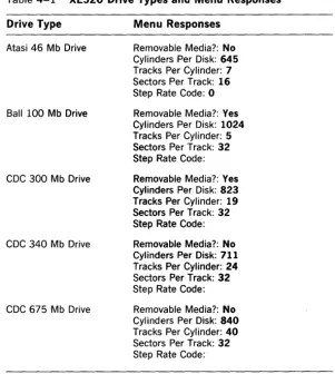
Table 4-1 XE520 Drive Types and Menu Responses
Drive Type Menu Responses
Atasi 46 Mb Drive
Ball 100 Mb Drive
CDC 300 Mb Drive
CDC 340 Mb Drive
CDC 675 Mb Drive
[image:43.404.31.333.196.533.2]Installing the XE520 BTOS System Software
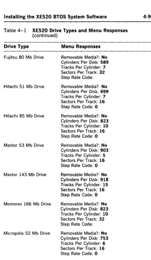
Table 4-1 XE520 Drive Types and Menu Responses (continued)
Drive Type Menu Responses
Fujitsu 80 Mb Drive
Hitachi 51 Mb Drive
Hitachi 85 Mb Drive
Maxtor 53 Mb Drive
Maxtor 143 Mb Drive
Memorex 166 Mb Drive
Micropolis 52 Mb Drive
Removable Media?: No Cylinders Per Disk: 589 Tracks Per Cylinder: 7 Sectors Per Track: 32 Step Rate Code: Removable Media?: No Cylinders Per Disk: 699 Tracks Per Cylinder: 7 Sectors Per Track: 16 Step Rate Code: 0 Removable Media?: No Cylinders Per Disk: 823 Tracks Per Cylinder: 10 Sectors Per Track: 16 Step Rate Code: 0 Removable Media?: No Cylinders Per Disk: 903 Tracks Per Cylinder: 5 Sectors Per Track: 16 Step Rate Code: 0 Removable Media?: No Cylinders Per Disk: 918 Tracks Per Cylinder: 15 Sectors Per Track: 16 Step Rate Code: 0 Removable Media?: No Cylinders Per Disk: 823 Tracks Per Cylinder: 10 Sectors Per Track: 32 Step Rate Code: Removable Media?: No Cylinders Per Disk: 753 Tracks Per Cylinder: 6 Sectors Per Track: 16 Step Rate Code: 0
[image:44.404.59.361.14.535.2]4-10 Installing the XE520 BTOS System Software
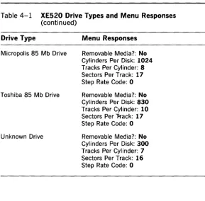
Table 4-1 XE520 Drive Types and Menu Responses
(continued)
Drive Type Menu Responses
Micropolis 85 Mb Drive
Toshiba 85 Mb Drive
Unknown Drive
Removable Media?: No Cylinders Per Disk: 1024
Tracks Per Cylinder: 8 Sectors Per Track: 17
Step Rate Code: 0 Removable Media?: No Cylinders Per Disk: 830
Tracks Per Cylinder: 10
Sectors Per "Frack: 17
Step Rate Code: 0 Removable Media?: No Cylinders Per Disk: 300
Tracks Per Cylinder: 7 Sectors Per Track: 16
[image:45.403.33.322.51.335.2]Section 5
Installing Workstation Software
To install BTOS workstation software onto the XE520 system disk, you use system utilities that you run from your workstation.
Before you can use your workstation for installation procedure, it must:
o have a floppy disk drive
5-1
o be connected to the first Cluster Processor (CPOO) in the XE520
The installation diskettes are divided into the following packages:
o BxxSTl (where xx is 26, 27, 28, or 38 depending on your workstation model), which contains the BTOS standard software.
o B25SUl, which contains workstation utilities. o B25CLl, which contains the cluster workstation
operating systems.
o B25LDl, which contains the workstation language development software.
Each workstation software release diskette is appropriately marked. As you proceed through the installation procedure, the installation utility tells you which diskette to insert.
Note: Before the XE520 can support workstations, you must install the following required packages: BxxSTl, B25SUl, and B25CLl. Although the other packages are optional, software contained in them may be required by some BTOS environmental software.
5-2 Installing Workstation Software
Installing Standard Workstation
Software
The standard workstation software allows you to boot the workstation from the XE520 and to install the BTOS workstation utilities.
To install the standard workstation software, complete the following:
1 Power on your XE520.
2 Power on your BTOS workstation.
Remember that the workstation must have a floppy drive and must be connected to CPOO of the XE520. 3 Insert the first BxxSTl diskette into [fO].
The Bxx designation should match the workstation you are using. For example, if you are using a B38
workstation, you would use diskette B38ST 1-1. 4 Reset your workstation.
The workstation boots from the floppy and the system displays the Signon screen.
5 Remove the write-protect tab from the second BxxSTl
diskette.
6 Remove the first BxxST 1 diskette and insert the second
BxxSTl diskette.
7 Type XE520 in the User name field. S Press GO.
The system displays a prompt about the old software in the <B20> directory.
9 Press one of the following: o GO to continue installation
If you press GO, the system displays the PATH command form and prompts you to enter a password if one exists. Proceed to step 10.
o ACTION-FINISH to abort the installation
If you press ACTION-FINISH, the system stops the installation and displays another BTOS Executive command line. Before attempting to install the software, make a backup copy of your <B20> directory.
Installing Workstation Software 5·3
11 Press GO.
The system copies other files onto the XE520 system. When these operations are complete, the systems asks you if you want to overwrite the [!sys]<sys>Sys.cmds file (if it exists).
12 Choose one of the following:
o If you are installing this workstation software as part of an initial XE520 software installation, press GO to overwrite the [!sys]<sys>Sys.cmds file. The system executes various commands and prompts you to reinsert the first BxxST1 diskette. Proceed to step 13.
o If you are updating your workstation software with this workstation release, you should not overwrite your [!sys]<sys>Sys.cmds file. Press CANCEL and then GO to prevent the current
[!sys]<sys>Sys.cmds file from being overwritten. The system executes various commands and prompts you to reinsert the first BxxST 1 diskette. Proceed to step 13.
Note: If you chose to overwrite your
[!sys]<sys>Sys.cmds file, or do so accidentally, you must add the master commands to this file after you have installed the workstation software (refer to your Standard Software documentation).
13 Remove the second BxxST1 diskette and reinsert the first BxxST1 diskette.
14 Press GO.
The system executes various commands.
When the software installation is complete, the system displays instructions for rebooting the workstation from the XE520 (refer to figure 5-1), and prompts you to press GO to continue.
15 Press GO.
The system displays instructions for continuing the software installation.
16 Remove the first BxxST 1 diskette.
17 Replace the write-protect tab on the second BxxST1 diskette and store the diskettes in a safe place.
5-4 Installing Workstation Software Figure 5-1 Rebooting Instructions
REBOOTING THE WORKSTATION Note the reboot instructions below:
A. Hold down the space bar and simultaneously reset the system.
8. When B,C,D,L,M,P,T: appears on the screen, enter T. C. The video will then display OS:.
1. If this system has a winchester disk, enter 240 then press return.
2. If this system has only floppy disk storage, enter 241 then press return.
D. The video will again display 8,C,D,L,M,P,T:. Enter B and the system will complete the boot process.
Installing the Workstation Utilities
Software
The workstation utility software (contained on six diskettes) installs workstation utilities and creates their associated command forms.
During the installation procedure, you will have the option of installing certain utilities.
To install the workstation utilities software, complete the following:
1 Sign on to your workstation system. 2 Insert the first B25SUI diskette into [fO].
3 Type XESoftware Installation at the BTOS Executive command line.
4 Press GO.
Installing Workstation Software 5-5 5 Choose one of the following:
o If you are installing this workstation software as part of an initial XE520 software installation, press GO to overwrite the [!sys]<sys>Sys.cmds file. The system executes various commands and prompts you to insert the second B25SU 1 diskette. Proceed to step 6.
o If you are updating your workstation software with this workstation release, you should not overwrite your [!sys]<sys>Sys.cmds file. Press CANCEL and then GO to prevent the current
[!sys]<sys>Sys.cmds file from being overwritten. The system prompt you to insert the second B25SUl diskette. Proceed to step 6.
Note: If you chose to overwrite your
[!sys]<sys>Sys.cmds file, or do so accidentally, you must add the master commands to this file after you have installed the workstation software (refer to your Standard Software documentation).
6 Remove the first B25SU 1 diskette and insert the second B25SUl diskette.
7 Press GO.
The system begins installing various utilities and then prompts you to install the first optional utility, BACKUP VOLUME.
Note: For a description of the utilities, refer to your Standard Software documentation.
S To install the BACKUP VOLUME utility and the other optional utilities on the remainder of the B25SU 1 diskettes, press GO in response to the utility's prompt.
If you decide not to install a particular optional utility, press CANCEL and GO in response to the utility's prompt.
As you cycle through the optional utility prompts for a given B25SU 1 diskette, the system prompts you to remove the diskette and insert the next one.
When you have cycled through the utilities on the last B25SUl diskette, the system tells you that the
5-6 Installing Workstation Software
9 Remove the last B25SU 1 diskette and store the diskettes in a safe place.
10 Reboot the XE520 and all the workstations in the cluster.
Installing Cluster Workstation Software
The cluster workstation software (contained on five diskettes) allows workstations to run within a BTOS cluster environment.
To install the BTOS cluster workstation software, complete the following:
1 Sign on to your workstation.
2 Insert the first B25CLI diskette into [fO].
3 Enter XESoftware Installation at the BTOS Executive command line.
4 Press GO.
The system prompts you to power down all other workstations.
5 After you have verified that all other workstations in the cluster are powered down, press GO.
The system automatically installs the following utilities:
Cluster Status Disable Cluster Resume Cluster
The system then prompts you to have a list of the model numbers of the workstations on your system. 6 Press GO.
The system displays a prompt asking you if you have B24 workstations in your cluster.
7 Press GO if you have B24 workstations in your cluster, or CANCEL-GO if you do not.
8 When the system prompts you, remove the first B25CLI diskette and insert the second B25CLI diskette.
9 Press GO.
During the remainder of the cluster software
Installing Workstation Software
10 If your workstation is of the type displayed in the prompt, press GO. If it is not, press CANCEL-GO.
5·7
As you progress through the cluster operating system prompts for a given B25CLl diskette, the system prompts you to remove the diskette and insert the next one.
When you have cycled through the cluster operating systems on the last B25CLl diskette, the system tells you that the cluster software installation is complete. 11 Remove the last B25CLl diskette and store the diskettes
in a safe place.
12 Reboot all the workstations in the cluster.
Installing Workstation Language
Development Software
The Language Development software (contained on two diskettes) consists of software tools that support BTOS programming languages.
To install the workstation Language Development software, complete the following:
1 Sign on to your workstation.
2 Insert the first B25LDl diskette into [fO].
3 Type XESoftware Installation at the BTOS Executive command line.
4 Press GO.
The system prompts you to power down all other workstations in the cluster.
5 After powering down the other workstations in the cluster, press GO.
The system begins installing the Language Development software.
The system displays a series of prompts that allow you to decide which Language Development tools you want to install.
6 To install a tool, press GO in response to the prompt.
If you decide not to install a particular tool, press CANCEL-GO in response to the prompt.
5-8 Installing Workstation Software
When you have cycled through the tools on the second B25LDl diskette, the system tells you that the
Language Development software installation is complete.
7 Remove the second B25LDl diskette and store the diskettes in a safe place.
Section 6
6-1Overview of System Configuration
Files
XE520 STOS uses several text files to define the system's hardware and software configurations. The system reads these text files when STOS is loaded into the XE520 processor boards (that is, when the system is booted).
Note: The system reads different sets of configuration files depending on the positions to which the keyswitch can be turned to boot the system. Refer to appendix B for details.
The following are the types of configuration files:
D Master configuration file
The master configuration file is used by the master processor (FPOO or DPOO) to determine the processor operating systems to be loaded at boot time. It contains an entry for each processor in the system, except the master processor. The entries define the version of XE520 STOS it loads on the processors. Other entries in this file define the processor configuration files for applicable processors.
D Processor configuration file
A processor configuration file defines the hardware and software configuration associated with a processor board.
For example, a File Processor (FP) or Disk Processor (DP) configuration file lists the device names and passwords for each disk drive under its control. A Cluster Processor (CP) or Terminal Processor (TP) configuration file defines parameters for a CP's or TP's input/output (I/O) ports.
Each configuration file also contains entries that define the dynamic block allocation parameters for the
processor. These parameters determine the size of I/O communications buffer space.
D Processor initialization file
A processor initialization file defines the system
6-2 Overview of System Configuration Files
D Queue index file
The queue index file defines the queues for which the Queue Manager is responsible.
D Spooler configuration file
The spooler configuration file contains entries for each printer in the system. A printer entry defines
parameters such as where the printer is connected and what print queue the printer is to serve.
D I/O device configuration files
I/O device configuration files define the hardware and software parameters of disk drives, printers, tape drives, and modems.
The necessary disk drive configuration files are included in the standard software release. Default configuration files for a parallel printer, a serial
printer, a half-inch tape drive, and a QIC tape drive are also provided. You can modify the printer and tape drive configuration files and create other I/O device configuration files by using the mCREATE
CONFIGURATION FILE command.
This section describes the configuration files related to the XE520 processor boards, disk drives, and I/O device configuration files. The processor initialization files, queue index file, and spooler configuration file are described in section 7.
The Master Configuration File
At boot time, the master processor (FPOO or DPOO) loads its own operating system, [sys]<sys>Syslmage.sys. (The operating system is also referred to as a system image.) It
then reads the default master configuration file,
[sys]<sys> Master.cnf, to determine the versions of BTOS for the other processor boards and the order in which to load them.
Overview of System Configuration Files
The master configuration file contains the following line entries:
o the nowatchdog entry
The line nowatchdog must be included in the master configuration file.
o the watchdog entry o processor BTOS entries
6-3
BTOS entries following the nowatchdog entry for each processor in the XE520 system, except the master processor. Each of these entries determines the version of BTOS to be run on the processor. Entries are ordered according to how their corresponding processors are configured in the XE520 enclosures. The first entry corresponds to the first processor board after the master processor, the next entry corresponds to the next processor board, and so on.
o include statement entries for processor configuration files
The master configuration file also contains an include entry for the processor's configuration files.
A CP or TP configuration file defines the I/O ports supported by the processor and the X, Y, and Z block allocations. An FP or DP configuration file defines the Y and Z block allocations and the internal disk devices associated with the processor. An SP configuration file defines the Y and Z block allocations for the SP.
Caution: You should not include the master processor and SP configuration files in the master configuration file. The system automatically assumes the master processor configuration file to be [sys] <sys> FpOO.cnf or
[sys]<sys>DpOO.cnf, and all SP configuration files to be [sys]<sys>Spnn.cnf, where nn is the SP number.
6-4 Overview of System Configuration Files
Sample Master Configuration File
The following is a sample master configuration file:
NoWatchDog
Cp [sys]<sys>CpBtos.sys Include [sys]<sys>CpOO.cnf Tp [sys]<sys>TpBtos.sys Include [sys]<sys>TpOO.cnf Dp [sys]<sys> DpBtos.sys Include [sys]<sys> DpOO.cnf Sp [sys] <sys>SpBtos.sys Fp [sys]<sys>SysImage.sys Include [sys]<sys>FpOl.cnf Cp [sys]<sys>CpBtos.sys Include [sys]<sys>CpOl.cnf
This master configuration file is for a system that contains, in ascending order by slot number, a master FP, a CP, a TP, a DP, an SP, a second FP, and a second CPo
The BTOS version entries comprise the processor name in the first column and the processor's BTOS version file in the second column. The master processor, and all
processors of the same type as the master, run the master version of BTOS, [sys]<sys>SysImage.sys. BTOS versions for all other processors take the form
[sys]<sys>ZpBtos.sys, where Zp represents the processor type (CP, TP, SP, FP, or DP).
Note that each BTOS version entry is followed by an include entry for that processor's configuration file (except for the SP, as discussed in previous cautionary note). The include entries are denoted by the word "Include" in the first column, followed by the processor's configuration file. Processor configuration files take the form
[sys]<sys>Zpnn.cnf, where Zp represents the processor type and nn is the processor's number within the system. This number uniquely identifies processor boards of the same type.
Overview of System Configuration Files 6-5
Processor Configuration Files
A processor configuration file defines the protocols and/or hardware configuration of a processor's I/O ports. It also includes the X, Y, and Z block allocations for the processor.
In addition to defining X, Y, and Z block allocations, processor configuration files for FPs and DPs define the disk drives that they support. For CPs and TPs, they define the terminal ports that they support. By convention,
processor configuration files always have the suffix .cnf.
Processor configuration file names take the form
[sys]<sys>Zpnn.cnf, where Zp is the processor type (such as FP, CP) and nn is the processor number (such as 00,01, or 02). For example, the first CP is CPOO, the second CP is CPOl, the third CP is CP02, and so on.
Refer to appendix A for a listing of default processor configuration files.
Dynamic Block Allocation
The system uses X, Y, and Z blocks to provide buffer space for various types of communications.
The system uses X blocks exclusively in the CP for data transmission to and from the workstations. The number of X blocks affects both the ability of the workstations to boot and workstation performance after booting. The default size of an X block is 2560 bytes.
Y blocks are the large IPC (Inter-Processor
Communications) communication blocks. They generally handle responses from a server process to a client process. The default size of an Y block is 2560 bytes.
Z blocks are the small IPC communications buffers, and the system uses them for the same purpose as Y blocks. The default size of a Z block is 100 bytes.